Environmental and Exploration Geophysics II Normal Incidence coincident
 Ray-Tracing tom. h. wilson@geo. wvu.")


")
 geometry. We usually")
 that the arrivals come in at the same time,")


- Slides: 51
Environmental and Exploration Geophysics II Normal Incidence (coincident source-receiver) Ray-Tracing tom. h. wilson@geo. wvu. edu Department of Geology and Geography West Virginia University Morgantown, WV
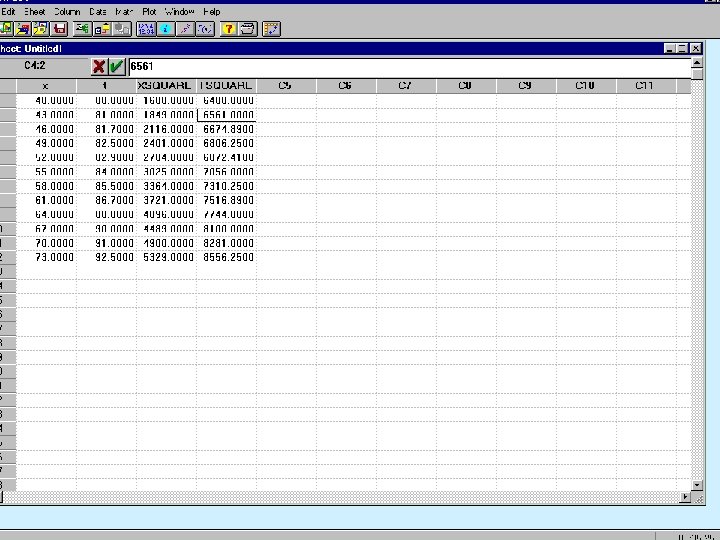
Feet 73 40
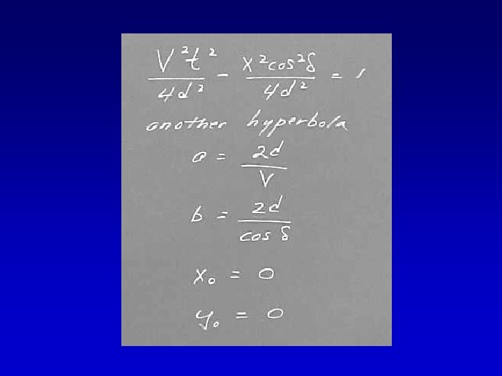
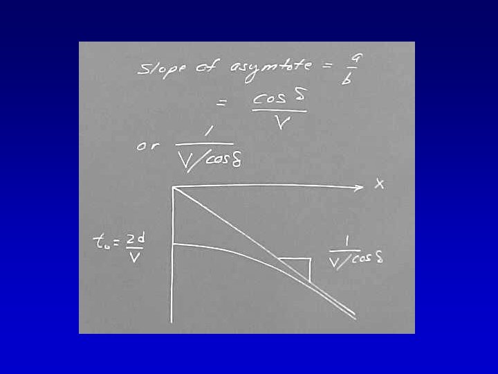
” “hy la o b r pe
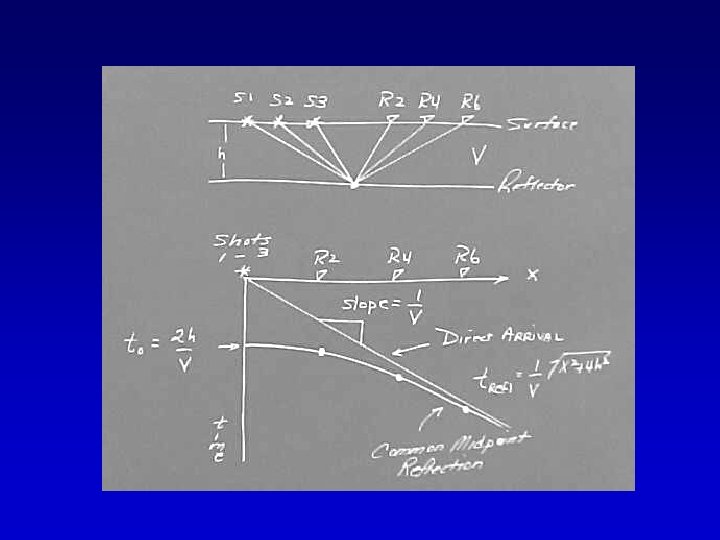
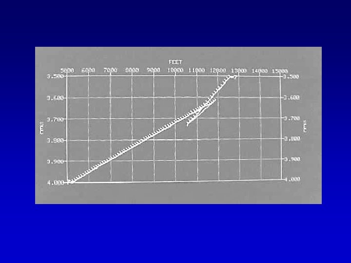
Fit a linear regression line to t 2 vs. X 2. e g ai r St h n t li The slope (a) =1/V 2 and the intercept (b) = t 02
This is referred to as a stacking chart. Stack can be translated as “sum, ” and all traces sharing the same midpoint are summed (or stacked) together - more on this later.
The effect of the moveout correction on the traces in the common midpoint (CMP) gather is to create a composite normal incidence trace that effectively shares a coincident source and receiver at the midpoint shared by all the traces in the gather. We’ll discuss CMP data in more detail in a couple lectures.
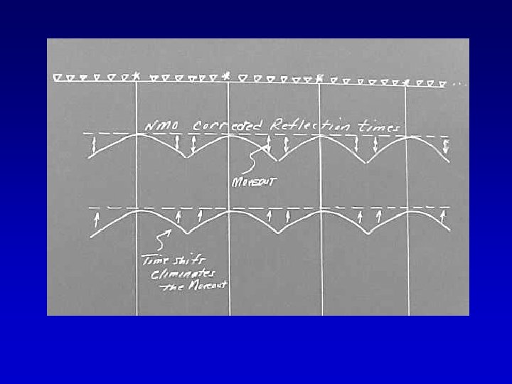
The NMO correction and its effect on the source- receiver (apparent) geometry. We usually think of the NMO correction as simply flattening out the reflection hyperbola - but consider the effect from the perspective of source receiver locations.
Note (in the preceding slide) that the arrivals come in at the same time, which, in the case of the flat horizontal reflector corresponds to the zero-offset arrival time. The process of applying the NMO correction effectively relocates source-receiver pairs to the midpoint between them. The NMO correction simulates coincident-source receiver acquisition geometry.
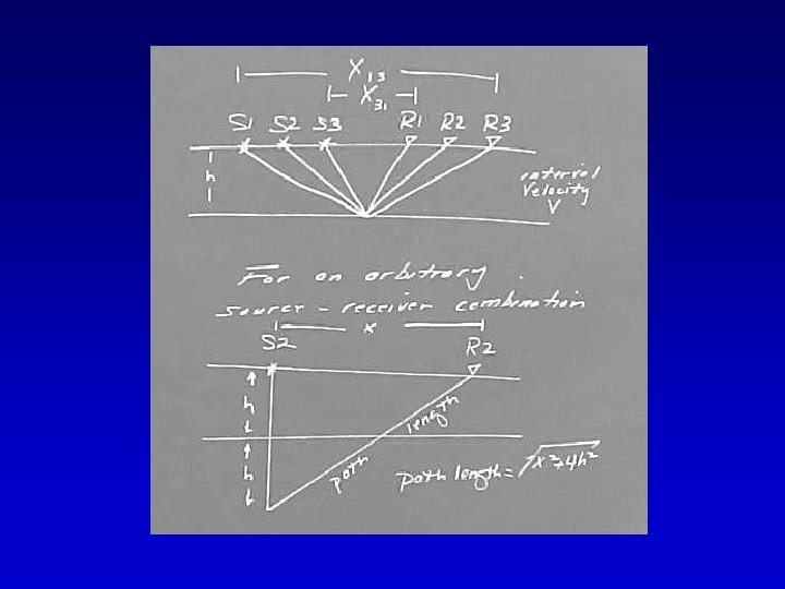
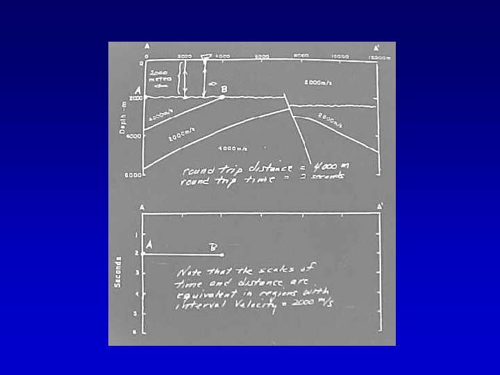
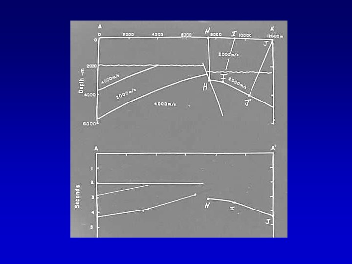
Recall Ray-Trace Exercise IV The simulated normal incidence ray-paths have the potential to provide a more accurate visual image of the subsurface.
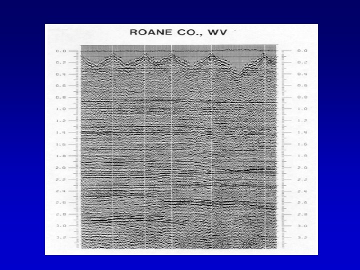
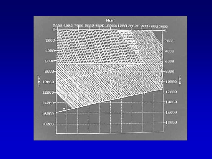
Thus when you look at data of the type we are interpreting over Granny Creek or in the foregoing example from Roane County, the individual traces shown in that section appear to be coincident source-receiver recordings and the ray paths are normal incident.
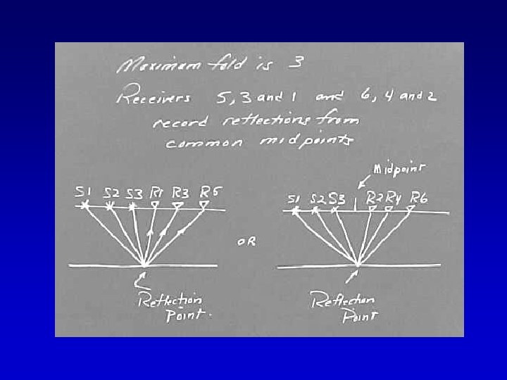
NMO corrections to the arrivals in a commonmidpoint gather yield the same coincidence of sources and receivers, but in this case all sources and receivers relocate to the same midpoint.
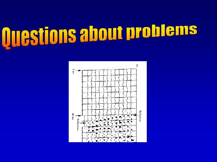
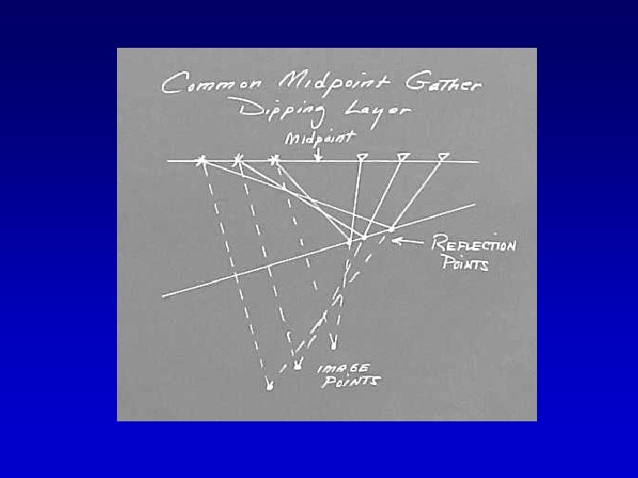
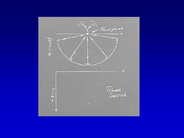
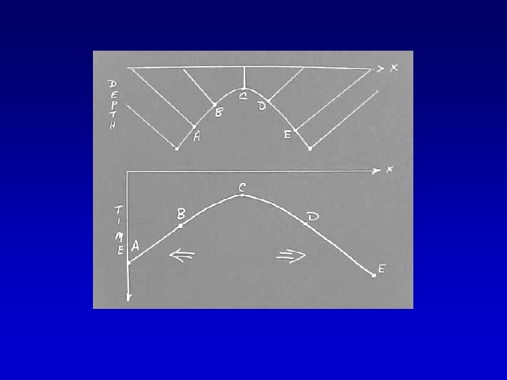
We have an easy to interpret image as long as the reflectors are flat and horizontal, but as soon as we introduce structure into the reflector geometry the records become complex in appearance. Consider, for example, a survey across a syncline. Consider the distribution of normal incidence ray-paths.
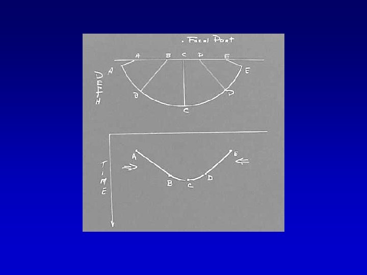
Consider what happens across the axis of the syncline and the relation of recording points to reflection points.
The record of reflection travel time to the various points in the subsurface contains dramatic image distortions - instead of a syncline we have an anticline
If you think this is only a theoretical construct - think again Pity the poor souls that keeping drilling these “anticlines!”
Reflection events are recorded downdip of the subsurface reflection points. We will introduce the refraction response later.
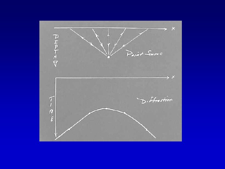
We have intentionally not included diffraction events.
Diffractor Diffraction Bring questions to class on Tuesday - Due on Thursday, Oct 12.
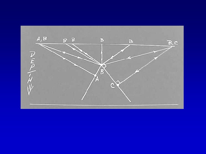
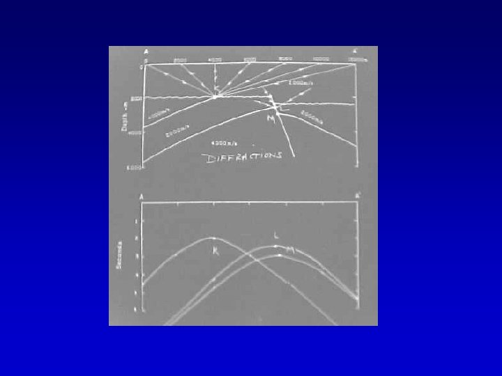
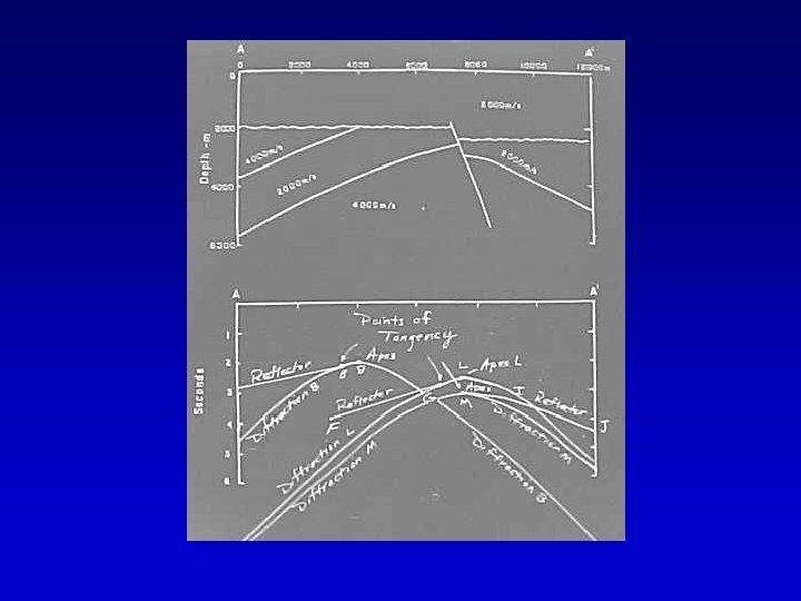
Now let’s introduce a variety of structural features into the subsurface and try and figure out how the time or seismic section should appear.
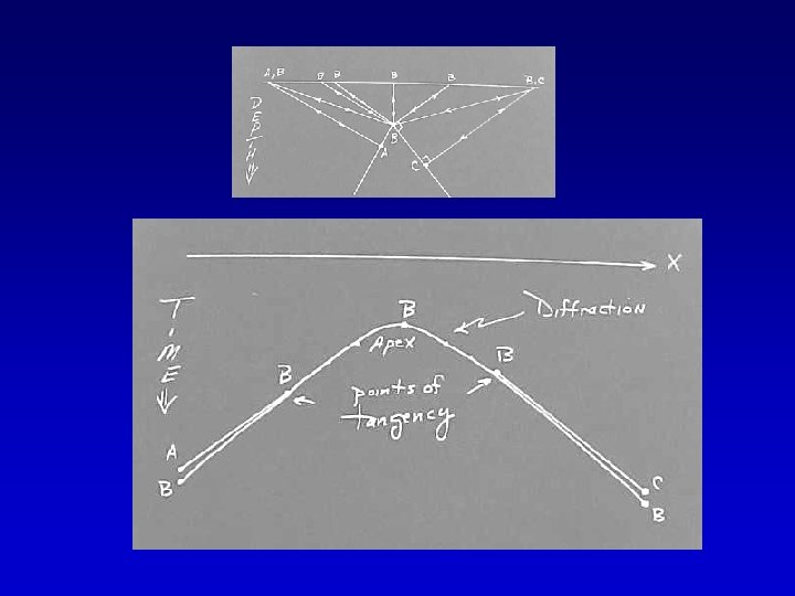
B L M Diffraction Points
Actual Location Points of Tangency
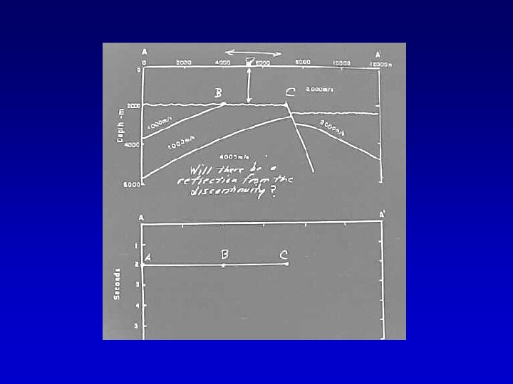
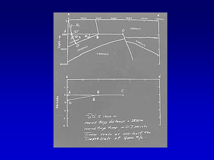
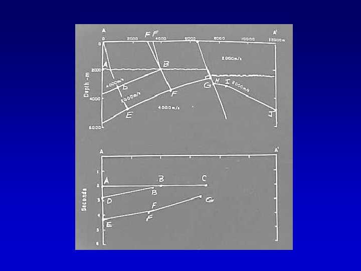
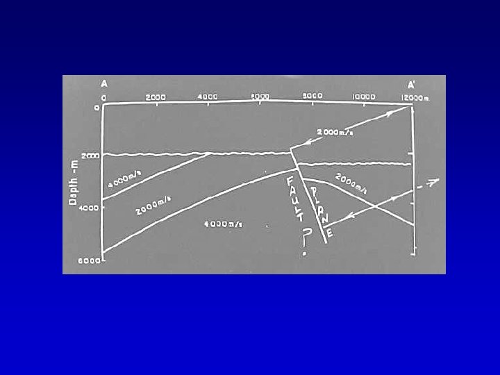
For the following week manually ray-trace the section below. For the purposes of this exercise assume that there is no impedance contrast and therefore no reflections or diffractions from the discontinuity shown in the shallow part of the section.