EntityRelationship ER Modeling Database Design Process Application 1
 Modeling")
Entity-Relationship (ER) Modeling

Database Design Process Application 1 External Model Application 2 Application 3 Application 4 External Model Application 1 Conceptual requirements Application 2 Conceptual requirements Application 3 Conceptual requirements Application 4 Conceptual requirements Conceptual Model Logical Model Internal Model

Stages in Database Design • • Requirements formulation and analysis Conceptual Design -- Conceptual Model Implementation Design -- Logical Model Physical Design --Physical Model

Database Design Process • Requirements formulation and analysis – Purpose: Identify and describe the data that are used by the organization – Results: Metadata identified, Data Dictionary, Conceptual Model-- ER diagram

Database Design Process • Requirements Formulation and analysis – Systems Analysis Process • Examine all of the information sources used in existing applications • Identify the characteristics of each data element – – numeric text date/time etc. • Examine the tasks carried out using the information • Examine results or reports created using the information

Conceptual Modeling Objective: to produce HIGH-LEVEL DATA MODEL GOALS – a complete understanding of the database structure, meaning (semantics), interrelationships, and constraints – A stable description of the database contents – Usually more expressive and general than data models of individual DBMSs – Vehicle of communication among database users, designers, and analysts.

Database Design Process • Conceptual Model – Merge the collective needs of all applications – Determine what Entities are being used • Some object about which information is to maintained – What are the Attributes of those entities? • Properties or characteristics of the entity • What attributes uniquely identify the entity – What are the Relationships between entities • How the entities interact with each other?

Database Design Process • Logical Model – How is each entity and relationship represented in the Data Model of the DBMS • • Hierarchic? Network? Relational? Object-Oriented?
 Model – Choices of index file structure")
Database Design Process • Physical ( Internal) Model – Choices of index file structure – Choices of data storage formats – Choices of disk layout

Database Design Process • External Model – User views of the integrated database – Making the old (or updated) applications work with the new database design
 – Provides a conceptually simple model for")
Data Models: History • Relational Model (1980’s) – Provides a conceptually simple model for data as relations (typically considered “tables”) with all data visible.
 – Encapsulates data and operations")
Data Models: History • Object Oriented Data Model (1990’s) – Encapsulates data and operations as “Objects” Books (id, title) Authors (first, last) Publisher Subjects

Intro. to ER Models • Entity/Relationship approach - one of the most well known modeling methods • Developed by P. Chen in 1976 - many variations since then • Data modeling is generally considered the most important component of the systems development process

Entity Relationship Diagrams A Simple ERD: Consider the following situation A customer places an order. The order consists of parts. Entity Relationship Customer Places An Organization An Association about which we between Entities wish to maintain information Altogether, a Database Another Relationship Orders Contain Another Entity Parts

ER NOTATION Entity type Attribute Key attribute Weak entity type Multivalued attribute Relationship type Derived attribute Identifying Relationship type Composite attribute

Relationship symbols Entity symbols A special entity that is also a relationship Relationship cardinalities specify how many of each entity type is allowed Attribute symbols Relationship degrees specify number of entity types involved

Entity • An Entity is an object in the real world (or even imaginary worlds) about which we want or need to maintain information – Persons (e. g. : customers in a business, employees, authors) – Things (e. g. : purchase orders, meetings, parts, companies) Employee

Figure 3 -4 System user Inappropriate entities System output Appropriate entities
 • Identifier (Key) - An attribute (or combination of attributes) that uniquely")
Identifiers (Keys) • Identifier (Key) - An attribute (or combination of attributes) that uniquely identifies individual instances of an entity type • Simple Key versus Composite Key • Candidate Key – an attribute that could be a key…satisfies the requirements for being a key

Characteristics of Identifiers • Will not change in value • Will not be null • No intelligent identifiers (e. g. containing locations or people that might change)

Attributes • Attributes are the significant properties or characteristics of an entity that help identify it and provide the information needed to interact with it or use it. (This is the Metadata for the entities. ) Birthdate First Middle Last Age Name Employee SSN Projects

Figure 3 -7 – A composite attribute An attribute broken into component parts

Weak Entities • Owe existence entirely to another entity Part# Invoice # Order Rep# Invoice# Contains Quantity Order-line

Figure 3 -9 a – Simple key attribute The key is underlined

Figure 3 -9 b – Composite key attribute The key is composed of two subparts
 and derived attribute (Years_Employed)")
Figure 3 -8 – Entity with a multivalued attribute (Skill) and derived attribute (Years_Employed) What’s wrong with this? Derived from date employed and current date Multivalued: an employee can have more than one skill

Relationships • Relationships are the associations between entities. They can involve one or more entities and belong to particular relationship types

Relationships Student Attends Class Project Supplier Supplies project parts Part

Relationships Student Attends Class Project Supplier Supplies project parts Part

Types of Relationships • Concerned only with cardinality of relationship 1 Assigned Employee 1 Truck Employee n Assigned 1 Project Employee m Assigned n Project Chen ER notation

Other Notations Employee Assigned Truck Employee Assigned Project “Crow’s Foot”

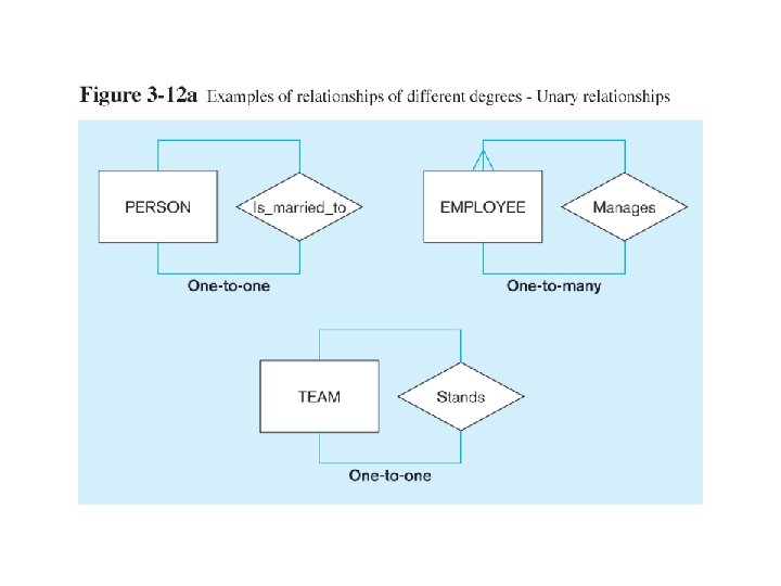
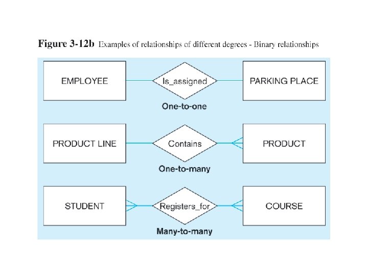
Degree of Relationships • Degree of a relationship is the number of entity types that participate in it –Unary Relationship –Binary Relationship –Ternary Relationship

Degree of relationships – from Figure 3 -2 One entity related to another of the same entity type Entities of two different types related to each other Entities of three different types related to each other

Cardinality of Relationships • One-to-One – Each entity in the relationship will have exactly one related entity • One-to-Many – An entity on one side of the relationship can have many related entities, but an entity on the other side will have a maximum of one related entity • Many-to-Many – Entities on both sides of the relationship can have many related entities on the other side

Cardinality Constraints • Cardinality Constraints - the number of instances of one entity that can or must be associated with each instance of another entity • Minimum Cardinality – If zero, then optional – If one or more, then mandatory • Maximum Cardinality – The maximum number
- Slides: 38