ENTC 4350 BIOMEDICAL INSTRUMENTATION I BASIC DIFFERENTIAL AMPLIFIER

ENTC 4350 BIOMEDICAL INSTRUMENTATION I BASIC DIFFERENTIAL AMPLIFIER

Introduction l The differential amplifier can measure as well as amplify small signals that are buried in much larger signals.
 input, and (+) input.")
l There are two input terminals, labeled ( ) input, and (+) input.

Superposition l If E 1 is replaced by a short circuit, E 2 sees an inverting amplifier with a gain of m. • Therefore, the output voltage due to E 2 is m. E 2

l Now let E 2 be short-circuited: • E 1 divides between R and m. R to apply a voltage of E 1 m/ (1+ m) at the op amp’s (+) input.

l This divided voltage sees a noninverting amplifier with a gain of (m + 1). • The output voltage due to E 1 is the divided voltage: • E 1 m/(1 + m) times the noninverting amplifier gain, (1 + m), which yields m. E 1

l Therefore, E 1 is amplified at the output by the multiplier m to m. E 1. • When both E 1 and E 2 are present at the (+) and ( ) inputs, respectively. • Vo is m. E 1 m. E 2.

l l The output voltage of the differential amplifier, Vo, is proportional to the difference in voltage applied to the (+) and ( ) inputs. Multiplier m is called the differential gain and is set by the resistor ratios.

l When E 1 = E 2 the output voltage is 0. • To put it another way, when a common (same) voltage is applied to the input terminals, Vo = 0.

Lab 6_Differential Amplifier l The gain of the amplifier below can be determined using the Superposition Principle. 22 k. W Rf ' ' 2. 2 k. W ─ Ri RS + 4. 7 k. W RD VOUT

Inverting Amplifier l Forcing V 2 to 0 develops an inverting amplifier with an output, VOUT of: 22 k. W Rf V 1 ' ' 2. 2 k. W ─ Ri RS + 4. 7 k. W RD VOUT

Non-inverting Amplifier l Forcing V 1 to 0 develops a non-inverting amplifier. 22 k. W Rf ' ' V 2 2. 2 k. W ─ Ri RS + 4. 7 k. W RD VOUT

l Applying Thevenin’s Theorem: 22 k. W Rf ' ' V 2 2. 2 k. W ─ Ri RS + 4. 7 k. W RD VOUT

l The output of the non-inverting amplifier is: 22 k. W Rf ' ' 2. 2 k. W Ri RTh ─ + VOUT

l The total output is the sum: l To balance the circuit, we set the coefficients to add to zero.
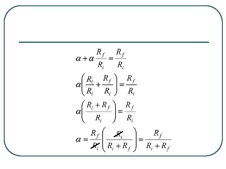
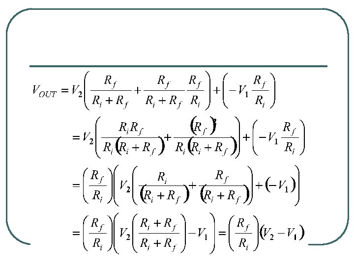

l So the balanced condition yields • and the differential gain Ad is

l Common-mode rejection of 60 cycle power line interference in medical instrumentation which measures difference potentials on the body is a fundamental problem. • Power-line interference may exceed the level of the signal being measured. • This bad news is often cancelled by the fact that the interfacing signal appears equally intense at both input terminals of the diff amp, and is therefore called a common-mode signal.

l If the diff amp is not perfectly balanced, as is always the case in the real world, then the common-mode signal input will cause an output signal that then constitutes interference with the desired amplified signal. • Since one of the functions of the diff amp is to reject the common-mode signal, we define a figure of merit, the common-mode rejection ratio (CMRR), which measures how well the rejection occurs.

l The common-mode rejection ratio CMRR is defined as the magnitude of the ratio of the differential voltage gain Ad to the common-mode voltage gain Ac.

l Ad equals VOUT divided by V 1 when node 2 is grounded, and V 1 is applied to node 1. • Also, AC equals VOUT divided by V 1 when node 1 is connected to node 2, and V 1 is applied again.

l In practice the CMRR is measured in the following steps: 1. Ground V 2, and apply a voltage V 1 to the upper terminal. 2. Measure the resulting VOUT. 3. Lift V 2 from ground and short the two input leads, then apply the same value of V 1. 4. Measure the resulting VOUT. 5. To compute CMRR, divide the results of step 2 by the result of step 4, and take the magnitude.

l The CMRR is a voltage ratio, and therefore in decibel units we may define CMRRdb as

Common-Mode Voltage l The simplest way to apply equal voltages is to wire inputs together and connect them to the voltage source.

l For such a connection, the input voltage is called the common-mode input voltage, ECM.

l Now Vo will be 0 if the resistor ratios are equal (m. R to R for the inverting amplifier gain equals m. R to R of the voltagedivider network. )

l Practically, the resistor ratios are equalized by installing a potentiometer in series with one resistor.

l The potentiometer is trimmed until Vo is reduced to a negligible value. • This causes the common-mode voltage gain, • Vo/ECM to approach 0. It is this characteristic of a differential amplifier that allows a small signal voltage to be picked out of a larger noise voltage.

l It may be possible to arrange the circuit so that the larger undesired signal is the common-mode input voltage and the small signal is the differential input voltage. • Then the differential amplifier’s output voltage will contain only an amplified version of the differential input voltage.
- Slides: 30