
ENTC 3320 Absolute Value HalfWave Rectifier l The

ENTC 3320 Absolute Value
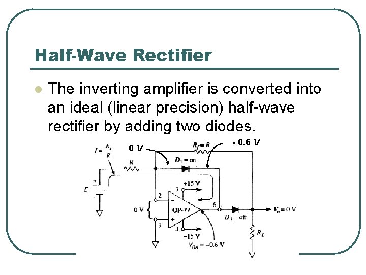
Half-Wave Rectifier l The inverting amplifier is converted into an ideal (linear precision) half-wave rectifier by adding two diodes. 0 V - 0. 6 V
l When E, is positive, diode D 1 conducts, causing the op amp’s output voltage, VOA, to go negative by one diode drop (0. 6 V). • This forces diode D 2 to be reverse biased. • The circuit’s output voltage Vo equals zero because input current I flows through D 1. • For all practical purposes, no current flows through Rf and therefore Vo = 0.
l Note the load is modeled by a resistor RL and must always be resistive. • If the load is a capacitor, inductor, voltage, or current source, then V 0 will not equal zero.
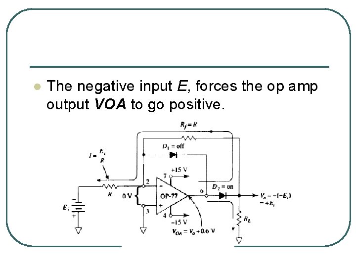
l The negative input E, forces the op amp output VOA to go positive.
l This causes D 2 to conduct. • The circuit then acts like an inverter, since Rf = Ri, and Vo =+E 1. • Since the (—) input is at ground potential, diode D 1 is reverse biased. • Input current is set by E/Ri and gain by ─Rf/Ri. • Remember that this gain equation applies only for negative inputs, and Vo can only be positive or zero.
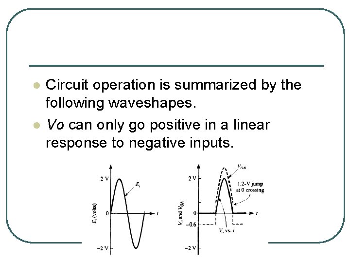
l l Circuit operation is summarized by the following waveshapes. Vo can only go positive in a linear response to negative inputs.
l l The most important property of this linear halfwave rectifier will now be examined. An ordinary silicon diode or even a hot-carrier diode requires a few tenths of volts to become forward biased. • • Any signal voltage below this threshold voltage cannot be rectified. However, by connecting the diode in the feedback loop of an op amp, the threshold voltage of the diode is essentially eliminated.
• For example. in Fig. 7 -2(b) let E, be a low voltage of — 0. 1 V. E, and R, convert this low voltage to a current that is conducted through D 2. • VOA goes to whatever voltage is required to supply the necessary diode drop plus the voltage drop across R~. Thus millivolts of input voltage can be rectified, since the diode’s forward bias is supplied automatically by the negative feedback action of the op amp.
l Finally, observe the waveshape of op amp output V~ in Fig. 7 -3. When E~ crosses 0 V (going negative), V(~ jumps quickly from — 0. 6 V to +0. 6 V as it switches from supplying the drop for D 2 to supplying the drop for D 1. This jump can be monitored by a differentiator to indicate the zero crossing. During the jump time the op amp operates open loop.
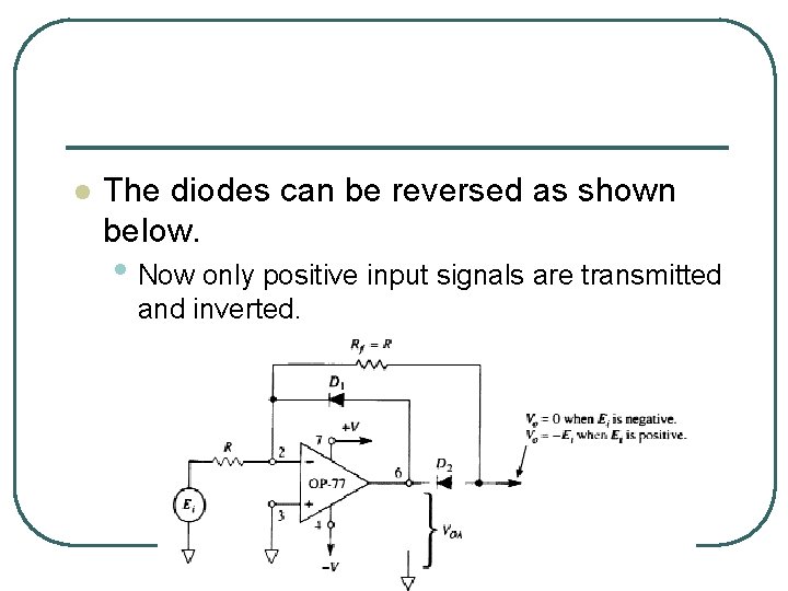
l The diodes can be reversed as shown below. • Now only positive input signals are transmitted and inverted.
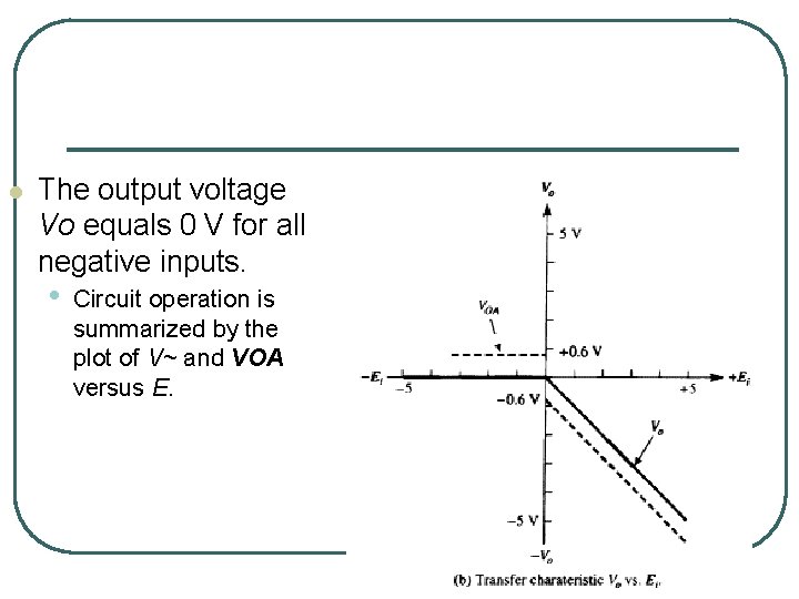
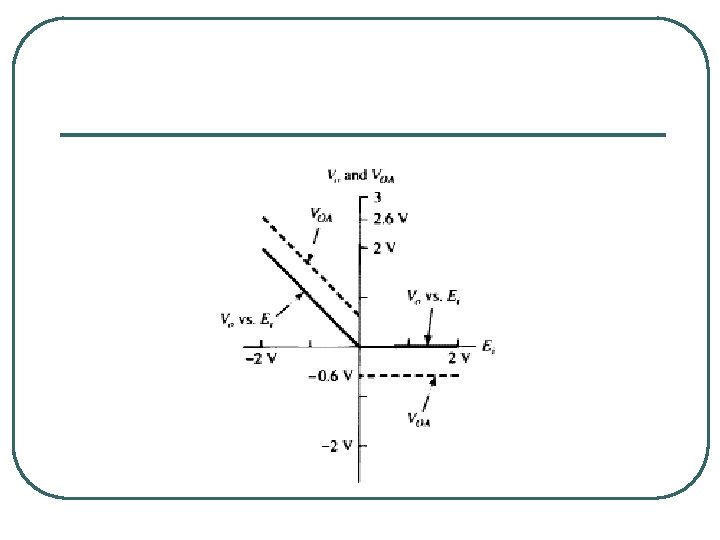
l The output voltage Vo equals 0 V for all negative inputs. • Circuit operation is summarized by the plot of V~ and VOA versus E.
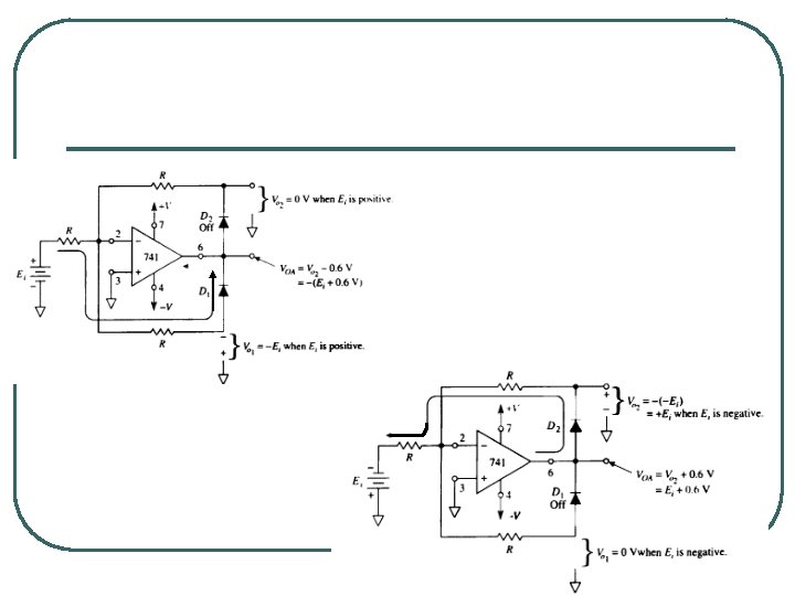
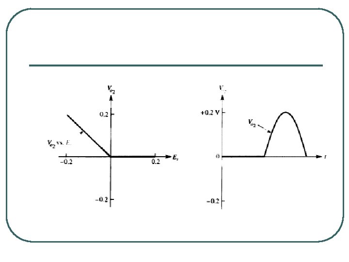
7 -1. 4 Signal Polarity Separator l The following circuit is an expansion of the previous circuits. • When E, is positive, diode D 1 conducts and an output is obtained only on output V 0, . • V 0, is bound at 0 V. • When E, is negative. D 2 conducts, V 0. = —(— E, ) = +E, . and V 0~ is bound at 0 V.
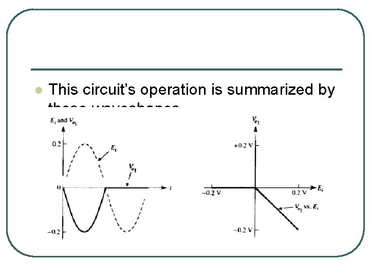
l This circuit’s operation is summarized by these waveshapes.
PRECISION RECTIFIERS: THE ABSOLUTE- VALUE CIRCUIT
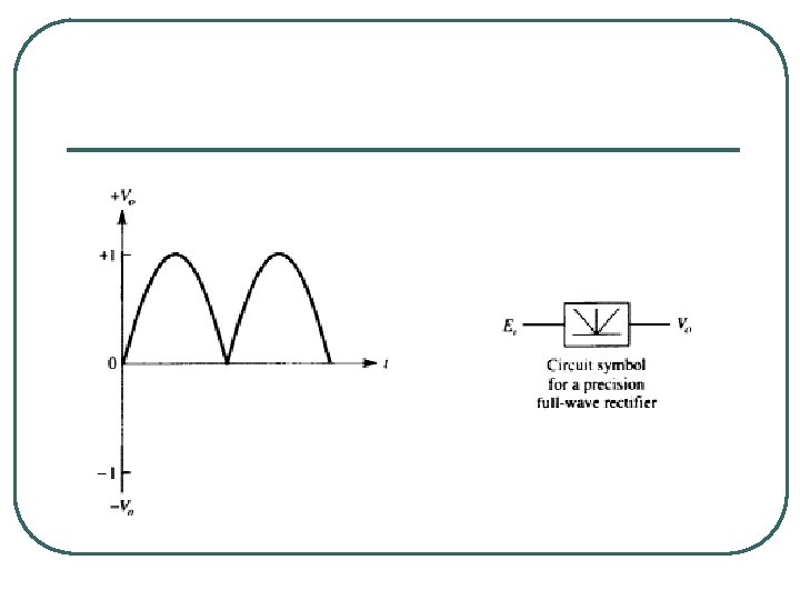
Introduction l The precision full-wave rectifier transmits one polarity of the input signal and inverts the other. • Thus both half-cycles of an alternating voltage are transmitted but are converted to a single polarity of the circuirs output.
l The precision full-wave rectifier can rectify input voltages with millivolt amplitudes. • This type of circuit is useful to prepare signals for multiplication, averaging, or demodulation.
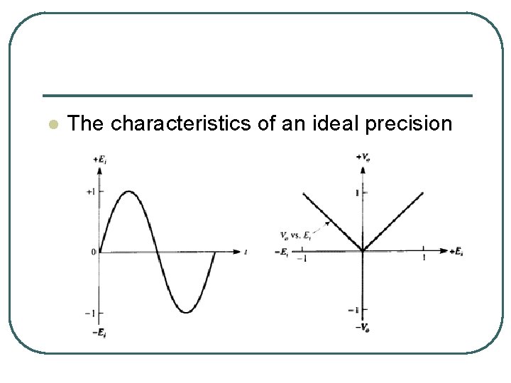
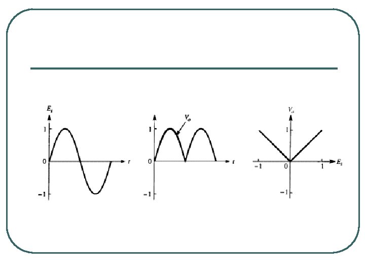
l The characteristics of an ideal precision rectifier are shown below.
l The precision rectifier is also called an absolute-value circuit. • The absolute value of a number (or voltage) is equal to its magnitude regardless of sign.
l For example, the absolute values of |+2 | and | 2 | are +2. • The symbol | | means “absolute value of. ” • In a precision rectifier circuit the output is either negative or positive, depending on how the diodes are installed.
Types of Precision Full. Wave Rectifiers
l Three types of precision rectifiers will be presented. • • The first is inexpensive because it uses two op amps. two diodes, and five equal resistors. • Unfortunately. it does not have high input resistance. ~o a second type is given that does have high input resistance but requires resistors that are precisely proportioned but not all equal. • Neither type has a summing node at virtual ground potential.
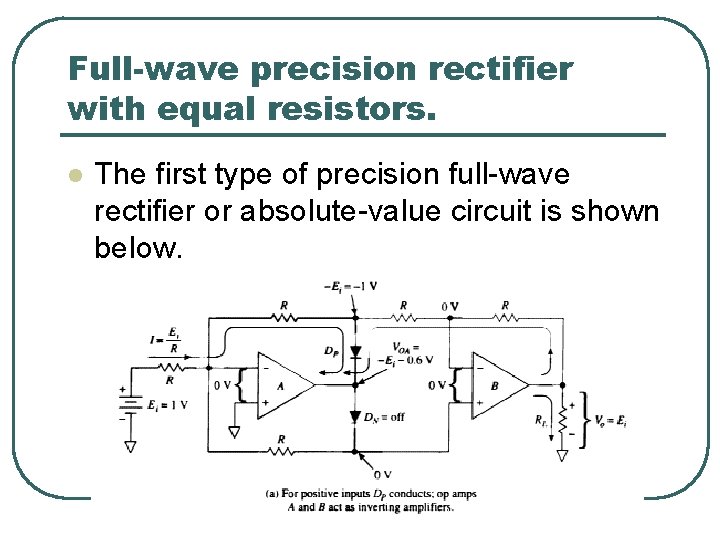
Full-wave precision rectifier with equal resistors. l The first type of precision full-wave rectifier or absolute-value circuit is shown below.
l This circuit uses equal resistors and has an input resistance equal to R.
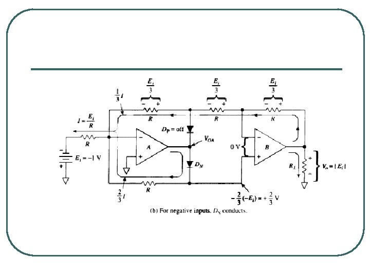
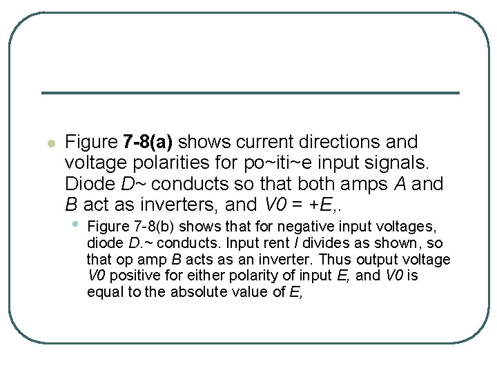
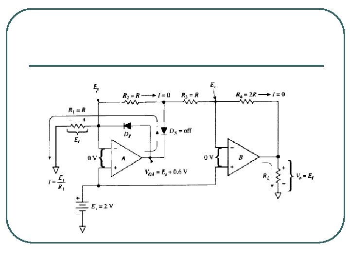
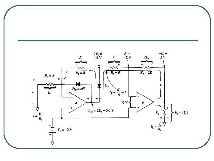
l Figure 7 -8(a) shows current directions and voltage polarities for po~iti~e input signals. Diode D~ conducts so that both amps A and B act as inverters, and V 0 = +E, . • Figure 7 -8(b) shows that for negative input voltages, diode D. ~ conducts. Input rent I divides as shown, so that op amp B acts as an inverter. Thus output voltage V 0 positive for either polarity of input E, and V 0 is equal to the absolute value of E,
- Slides: 33