ENTC 3320 555 TIMER 555 Timer IC Timer


. It")


- Slides: 20
ENTC 3320 555 TIMER
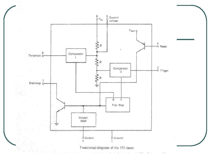
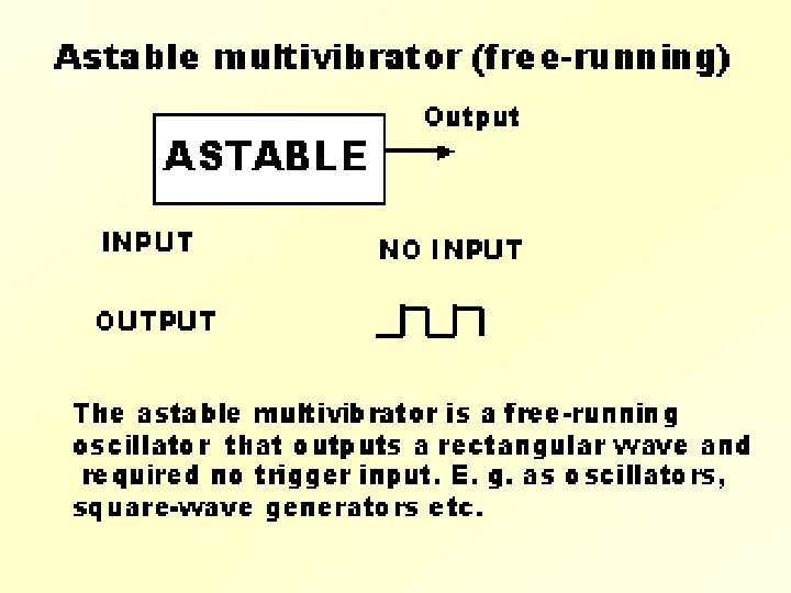
555 Timer IC Timer l The 555 timer has essentially two modes of operation: • Astable (free running) multivibrator and • Monostable (one shot) multivibrator Gnd 1 Trigger 2 Output 3 Reset 4 8 +Vcc 555 Timer 7 Discharge 6 Threshold 5 Control voltage
Pin Functions l l l PIN 1 Ground--usually connected to ground. The voltage should be the most negative of any voltage appearing at the other pins. PIN 2 Trigger--level-sensitive point to 1/3 VCC. When the voltage at this pin is brought below 1/3 VCC the flip-flop is set causing pin 3 to produce a high state. Allowable applied voltage is between VCC (pin 8) and ground (pin 1).
• Pin 3 Output--level here is normally low and goes high during the timing interval. Since the output stage is active in both directions, it can source or sink up 200 m. A. • Pin 4 Reset--when voltage at this pin is less than 0. 4 V, the timing cycle is interrupted returning the timer to its nontriggered state. This is an overriding function so that the timer can not be triggered unless reset is released (pin 4 > 1. 0 V). When not used, connect to VCC.
• Pin 5 Control voltage--internally derived 2/3 VCC point. A resistor-to-ground or an external voltage may be connected to pin 5 to change the comparator reference points. When not used for this purpose, a capacitor-to-ground greater than or equal to 0. 01 m. F is recommended for all applications. • Pin 6 Threshold--level sensitive point to 2/3 VCC. When the voltage at this pin is brought greater than 2/3 VCC. , the flip-flop is reset causing pin 3 to produce a low state.
• Pin 7 Discharge--collector of a transistor switch to ground (pin 1). It is normally used to discharge the timing capacitor. • Pin 8 VCC--the power-supply voltage connected here can range from 4. 5 to 16 V with respect to ground (pin 1).
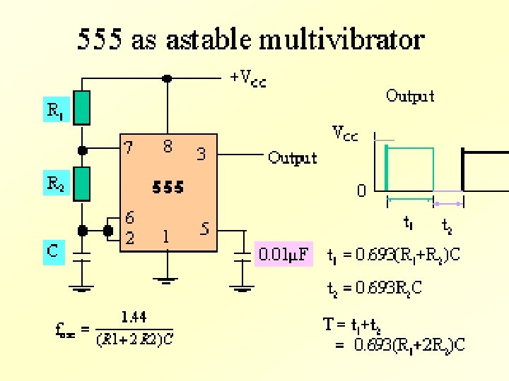
Astable Multivibrator Reset Discharge Threshold Trigger
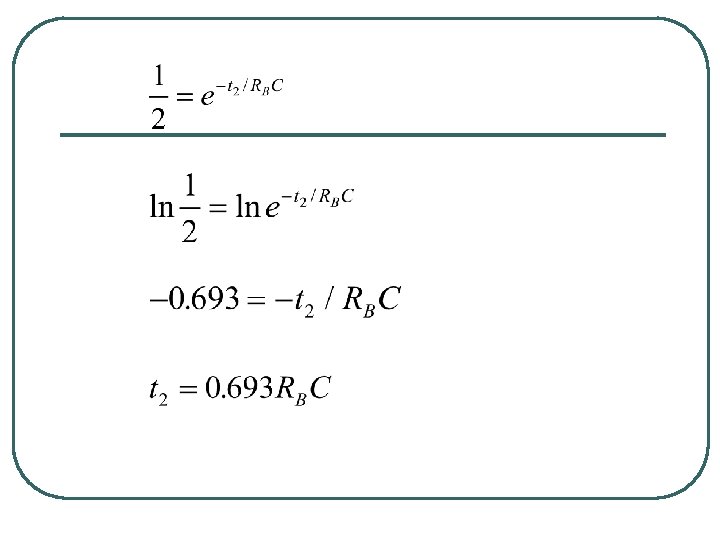
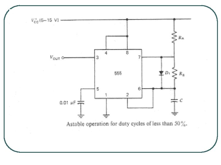
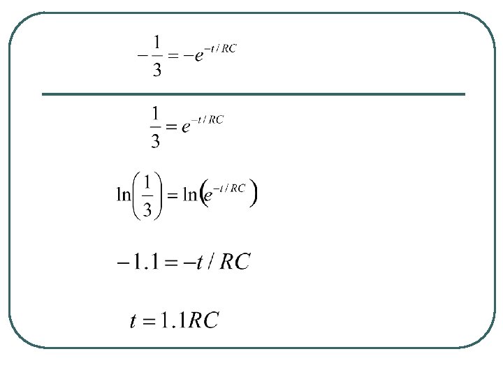
The charge/discharge equation for a RC circuit is: The charging circuit is through RA, RB, and C.
The discharging circuit is through RB and C.
The duty cycle will always be greater than 50%.
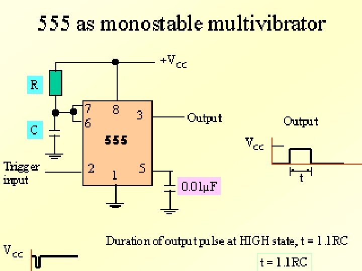
The charge equation for a RC one shot is: