Engineering Mechanics Equilibrium of Rigid Bodies Equilibrium System

Engineering Mechanics Equilibrium of Rigid Bodies

Equilibrium • System is in equilibrium if and only if the sum of all the forces and moment (about any point) equals zero.

Supports and Equilibrium • Any structure is made of many components. • The components are the be connected by linkages. • Other wise the structure will lose its integrity. • Different component of structure talk to each other via linkages. • The structure should be globally supported to prevent it from falling over.

Different Structural Supports • Supports are required to maintain system in equilibrium. • Too few supports makes system unstable general loading • Too many supports make the system overrigid.
 and")
Constraints and Reactions • • There is an intricate relationship between kinematics (motion) and reactions (forces). Always note that in the case of supports displacement (rotation) and force (torque) in any given direction are complementary. If a support rigidly constrains a given degree of freedom (DOF) for a rigid body then it gives rise to a reaction corresponding to that DOF. Similarly if a support freely allows motion of particular DOF then there is no reaction from the support in that direction.

Support reactions in 2 D structures

Simple Examples Roller Support Fixed Support

Using Symmetry to convert 3 D problems to 2 D (adapted from http: //oli. web. cmu. edu) • • • Box has 3 -planes of symmetry. Loading had only one plane of symmetry Using symmetry and static equivalence, the problem can be converted into a 2 D problem
")
Simple Example (http: //oli. web. cmu. edu)
 • Single most important concept in engineering mechanics. • Zoom")
Free Body Diagram (FBD) • Single most important concept in engineering mechanics. • Zoom in on a given component of a structure. • Means replace supports (connections) with the corresponding reactions. • Replace kinematic constraints with corresponding reactions. • Concepts will get more clear as we proceed further.

Simple examples FBD • Copyright, Dr. Romberg

More Examples of FBD

Equations of equilibrium in 2 D • Three equations per free body. • More than three equations per free body is illegal. • C We can also use equations like this or like this where A, B, C are not in a straight line

Problem 1 • Determine the tension in cable ABD and reaction at support C.


Categories of Equilibrium in 2 D

Adequacy of Constraints

Single Rigid Body Supported Globally
 overhead garage door consists of a uniform")
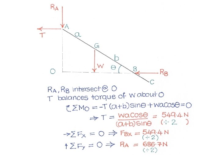
Problem 2 • A 70 kg (W) overhead garage door consists of a uniform rectangular panel AC 2100 mm high (h), supported by the cable AE attached at the middle of the upper edge of the door and by two sets of frictionless rollers at A and B. Each set consists of two rollers one either side of the door. The rollers A are free to move in horizontal channels, while rollers B are guided by vertical channels. If the door is held in the position for which BD=1050 mm, determine (a) the tension in the cable AE, (2) the reaction at each of the four rollers. Assume a = 1050 mm, b = 700 mm

Multiple Rigid Bodies Connected To Each Other

Pin Connections • All figures from http: //oli. web. cmu. edu

Modeling 3 D Problem as 2 D

Point Connections

Contd. .

Contd. .

Free Body Diagram at Pin-Connection

Summary • Pin connection • Pin support

Roller

Slot Connection

Non-Symmetrical but bodies connected by pin are very close to each other

Free body diagrams – Examples 32

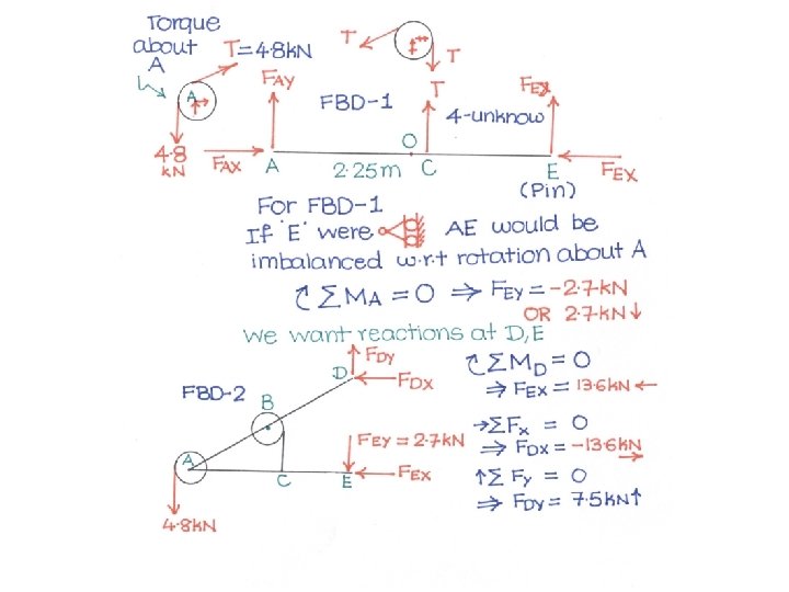
Problem 3 • Knowing that each pulley has a radius of 250 mm, determine the components of reactions at D and E.

Link: Two-Force Member • Member with negligible weight and arbitrary shape connected to other members by pins

Two Force member

Hydraulic Cylinder

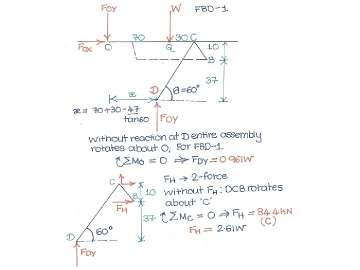
Problem 4 • The car hoist allows the car to be driven on to the platform, after which the rear wheel is raised. If the loading from the rear wheel is 3300 kg, determine the force in the hydraulic cylinder AB. Neglect the weight of the platform itself. Member BCD is a right angle bell crank pinned to the ramp at C

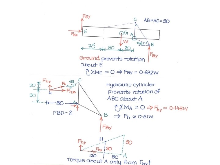
Problem 5 • An adjustable tow bar connecting the tractor unit H with the landing gear J of a large aircraft is shown in the figure. Adjusting the height of the hook F at the end of the tow bar is accomplished by the hydraulic cylinder CD is activated by a small hand-pump (not shown). For the nominal position shown of the triangular linkage ABC, calculate the force P supplied by the cylinder to the pin C to position the tow bar. The rig has a total weight of 220 kg and is supported by the tractor hitch E.

System constrained to various degrees

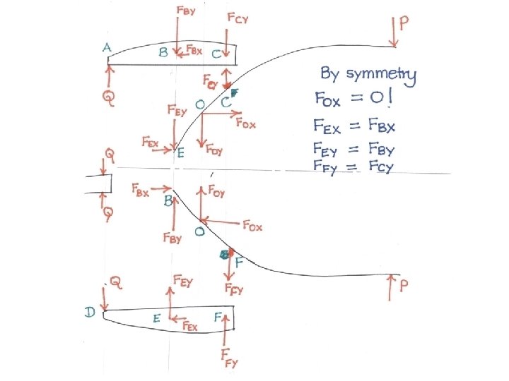
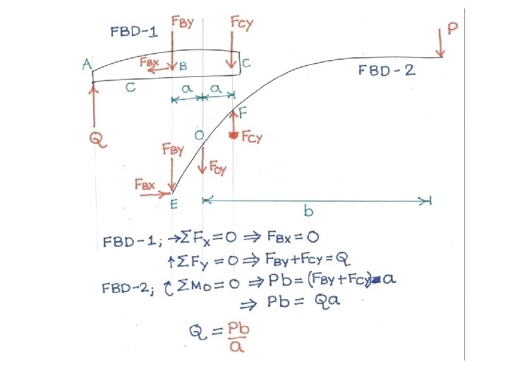
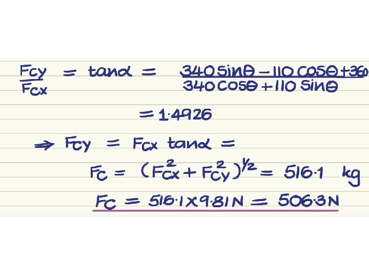
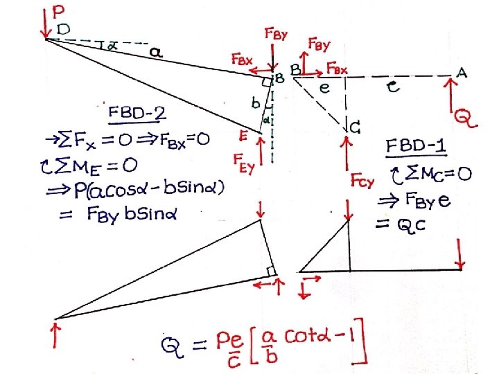
Problem 6 • For the paper punch shown in the figure find the punching force Q corresponding to a hand grip P.

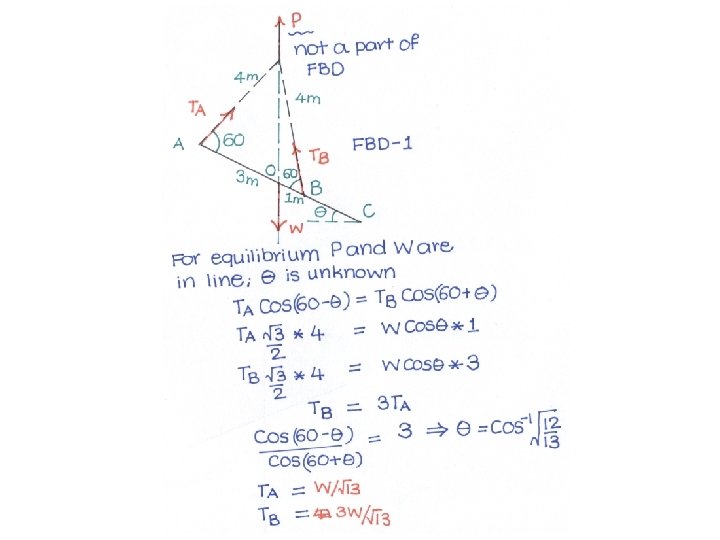
Problem 7 Meriam, , Statics The uniform beam has an overall length of 6 m and a mass of 300 kg. The force P applied to the hoisting cable is slowly increased to raise the ring C, the two 4 m ropes AC and BC, and the beam. Compute the tensions in the ropes at A and B when the beam is clear of its supports and the force P is equal to the weight of the beam

Problem 8 The figure shows a special rig for erecting vertical sections of a construction tower. The assembly A has a mass of 1. 5 Mg and is elevated by the platform B which itself has a mass of 2 Mg. The platform is guided up the fixed vertical columns by rollers and is activated by the hydraulic cylinder CD and links EDF and FH. For the particular position shown calculate the force R exerted by the hydraulic cylinder at D. Neglect mass of cylinder and links.

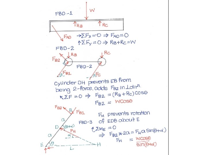
Problem 9 A hydraulic-lift table is used to raise a 1000 kg crate. It consists of two identical linkages on which hydraulic cylinders exert equal forces. Members EDB and CG are each of length 2 a, and member AD is pinned to the midpoint of EDB. If the crate is placed on the table, so that half of its weight is supported by the system shown, determine the force exerted by each cylinder in raising the crate for θ = 60 deg, a = 0. 70 m, and L = 3. 20 m. Show that the result obtained is independent of distance d.

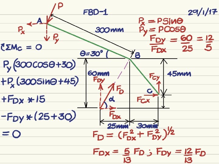
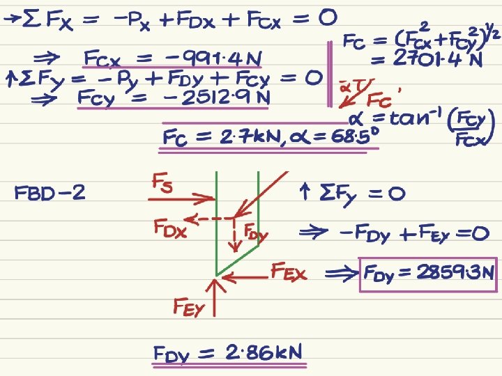
Problem 1 • The shear shown is used to cut and trim electroniccircuit board laminates. For the position shown, determine (a) the vertical component of force exerted on the shearing blade at D, and (b) the reaction at C. The value of P = 400 N

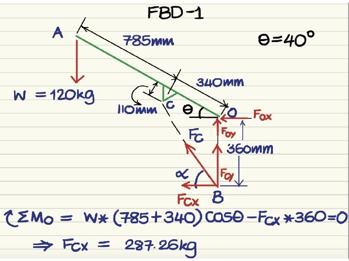
Problem The small crane is mounted on one side of the bed of a pickup truck as shown. The weight of the barrel is 120 kg. For the piston, = 40º, determine the magnitude of the force supported by the pin at O and the oil pressure P against the 50 mm diameter piston of the hydraulic cylinder BC.

Problem 2 • Obtain the clamping force Q developed for the pliers when the handle force is P.

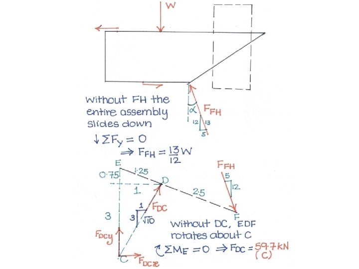
Problem 3 • A 500 -kg concrete slab is supported by a chain and sling attached to the bucket of the front-end loader shown. The action of the bucket is controlled by two identical mechanisms, only one of which is shown. Knowing that the mechanism supports half of the 500 -kg slab, determine the force (a) in the cylinder CD, (b) in cylinder FH.

Problem 4 H • The elevation of a platform is controlled by two identical mechanisms only one of which is shown. A load of 5 k. N is applied to the mechanism shown. Knowing that the pin at C can transmit only a horizontal force, determine (a) the force in link BE, (b) the components of the force exerted by the hydraulic cylinder on pin H.

Problem 5 • A hydraulic lift platform for loading trucks supports a weight W of 5000 N. Only one side of the system has been shown; the other side is identical. If the diameter of the piston in the cylinder (two) is 40 mm, what pressure p is needed to support W when θ = 60 o. Assume l = 240 mm, d = 600 mm, and e = 100 mm. Neglect friction everywhere.

Problem 6 • A semicircular rod ABCD is supported by a roller at D and rests on two frictionless cylinders at B and C. Find the maximum angle force P can make from the vertical if applied at point A and the rod remains in equilibrium.

Problem 11 • In the toy folding chair shown, members ABEH and CFK are parallel. Determine the components of all forces acting on member ABEH when a 160 N weight is placed on the chair. Draw completely all free body diagrams required. It may be assumed that the floor is frictionless and that half the weight is carried by each side of the chair and is applied at point M as shown.
- Slides: 64