Engineering Mechanics 17 ME 1001 LTP 3 0
 L-T-P : 3 -0 -2 Credits: 4 Plane trusses")


 The convention for internal forces, i. e. , the")


 3. When two members meet")


- Slides: 34
Engineering Mechanics (17 ME 1001) L-T-P : 3 -0 -2 Credits: 4 Plane trusses
Session Outcomes At the end of this session, Students will be able to • Understand the real time application of a truss structure. • Analyze the internal forces in a stable truss. • Solve relevant problems.
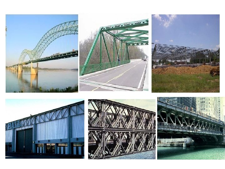
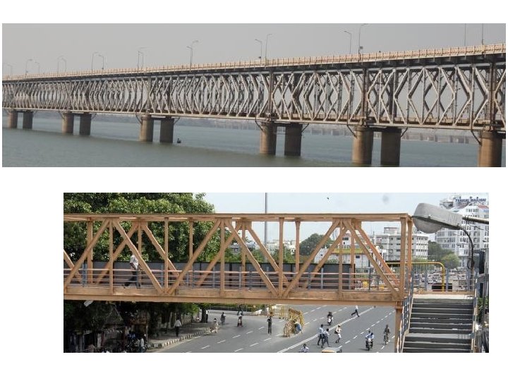
STRUCTURES Plane Trussed Bridge Space Truss Braced Frame
TRUSSES
Definition of a Truss • A truss is a structure which is made of straight slender bars that are joined together at their end by pins or by riveted/welded. • A truss is a fully constrained and stationary structure used for supporting loads. • A truss is held in position by the supports and the loads are applied only at joints. 6 - 8
Simple Truss The basic element of a plane truss is three members (bars, angles, tubes, etc) arranged to form a triangle. To this base triangle, two more members are added to locate a new joint, and the process continued to form the complete truss. The truss built in such a manner is called as ‘Simple Truss’.
Types of trusses
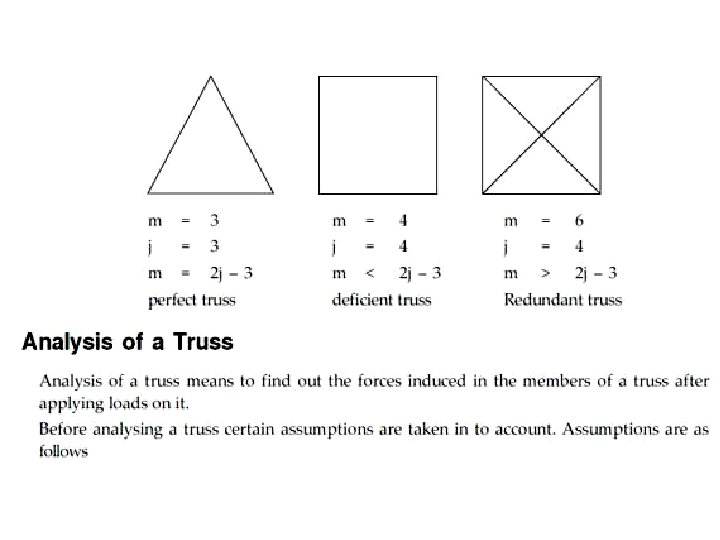
Simple Trusses • A rigid truss will not collapse under the application of a load. • A simple truss is constructed by successively adding two members and one connection to the basic triangular truss. • In a simple truss, m = 2 j- 3 • where m is the total number of members and j is the number of joints. 6 - 11
MAXWELL'S TRUSS EQUATION: To distinguish between "statically determinate structure" and "statically indeterminate structure" Maxwell formulated an equation involving the number of linkages (m) and number of joints (j). statically determinate structures statically indeterminate or redundant truss unstable or deficient truss
• When forces tend to pull the member apart, it is in tension. When the forces tend to compress the member, it is in compression. The free body diagram of a member shows that it is acted upon by two equal and opposite forces. The hinged joint permits members to rotate with respect to each other and hence the members are subjected to purely axial forces. T T Tension Member (Tie)
C C Compression Member (Strut) The convention for internal forces, i. e. , the action of forces in the members on the joints is shown. T TENSION C COMPRESSION
Transmission of force through members of truss ANIMATION
Analysis of trusses The following two methods are used to analyze any truss structure 1. Method of Joints 2. Method of Sections
Steps to be followed for METHOD OF JOINTS : • First check the given truss is perfect or not using the relation m=2 j-3 • Consider the whole truss as free body and calculate the support reactions using the three conditions of equilibrium i. e Fx=0, Fy=0 and M=0 • Now consider each joint as FBD and find out the unknown axial forces in the connected members by applying equations of equilibrium Fx=0 and Fy=0 • The analysis is continued with the next joint with two unknowns (preferably), until the forces in all the members are obtained and tabulate all the results.
Analysis of Trusses by the Method of Joints • Dismember the truss and create a freebody diagram for each member and pin. • The two forces exerted on each member are equal, have the same line of action, and opposite sense. • Forces exerted by a member on the pins or joints at its ends are directed along the member and equal and opposite. • Conditions of equilibrium on the pins provide 2 n equations for 2 n unknowns. For a simple truss, 2 n = m + 3. May solve for m member forces and 3 reaction forces at the supports. • Conditions for equilibrium for the entire truss provide 3 additional equations which are not independent of the pin equations. 6 - 20
Quiz 1. 2. 3. 4. 5. 6. What are different types of structures? Define truss? Distinguish truss and frame? How do you form a simple truss? How do you check a truss is rigid? How do you analyse internal forces of members of a truss?
Zero Force Members • Truss analysis using the method of joints is greatly simplified if one is able to determine those members which support no loading (zero-force members) • These zero-force members are used to increase stability of the truss during construction and to provide support if the applied loading is changed
• If only two members form a truss joint and no external load or support reaction is applied to the joint, the members must be zero-force members. • If three members form a truss for which two of the members are collinear, the third member is a zero-force member provided no external force or support reaction is applied.
IDENTIFICATION OF ZERO FORCE MEMBERS : 1. When two of the three members meeting at a joint are collinear, and no load is acting at the joint, then the force in the third member is zero. F A A F F F 2. When two members meet at a joint where no load is acting, then the forces in those members are zero. A A A
IDENTIFICATION OF ZERO FORCE MEMBERS : (contd. . ) 3. When two members meet at a joint where there is a support such that the support reaction is collinear with any one member, then the force in the other member is zero. F=VA A VA
Zero-force members • Frequently the analysis can be simplified by identifying members that carry no load – two typical cases are found • When only two members form a non-collinear joint and there is no external force or reaction at that joint, then both members must be zero-force If either TCB or TCD ≠ 0, P A B then C cannot be in C equilibrium, since there is no restoring force towards the right. D E Hence both BC and CD are zero-load members here.
When three members form a truss joint for which two members are collinear and the third is at an angle to these, then this third member must be zero-force in the absence of an external force or reaction from a support A B C D B TAB E TBC TBD Here, joint B has only one force in the vertical direction. Hence, this force must be zero or B would move (provided there are no external loads/reactions) Also TAB = TBC
• While zero-force members can be removed in this configuration, care should be taken – any change in the loading can lead to the member carrying a load – the stability of the truss can be degraded by removing the zeroforce member P A B D E C You may think that we can remove AD and BD to make a triangle. This satisfies the statics requirements However, this leaves a long CE member to carry a compressive load. This long member is highly susceptible to failure by buckling.
Problem set-4. 3 C 1 A 2 3 60° 4 5 D B P 1. Calculate the axial force in each bar of the simple truss supported and loaded as shown in the figure. The triangle ACB is isosceles with 30ᵒ angles at A and B and P = 5 k. N.
E C A F B D G H P 2. Prove that a tensile force equal to the applied load P is produced in the bar DE of the truss shown in the figure.
500 N 0. 6 m 4 5 500 N 1 3 2 0. 9 m 6 3. Determine the axial force in each bar of the plane truss loaded as shown in the figure.
Problem set-4. 3 3 m 6 1. 5 m 3 m 1 5 3 4 2 P 4. Determine the axial force in each bar of the plane truss loaded as shown in the figure.
8 6 7 9 45° 5 2 45° 5 k. N 1 3 4 5 k. N 5. Determine the axial force Si in each bar of the plane truss supported and loaded as shown in the figure.