Engineering Graphics TA 101 INTRODUCTION Design Cycle Recognition


 : CAD refers to the use")

 2. Relative Coordinate systems (@ X")
 5, 5 3, 3 7, 3 Command: line Start")

")
")
")


- Slides: 31
Engineering Graphics TA 101
INTRODUCTION Design Cycle Recognition of need Specifications Design Prototype Testing Production Drafting/Modeling CAD/CAE
Ø Drafting: It is the technique of generating 2 D drawings called sketches. The sketches convey all the information needed to fabricate the design. It is called the language of the engineers. Ø Modeling: It defines the building of 3 D models on the computer screen. 3 D models, pictures the design that you see or imagine.
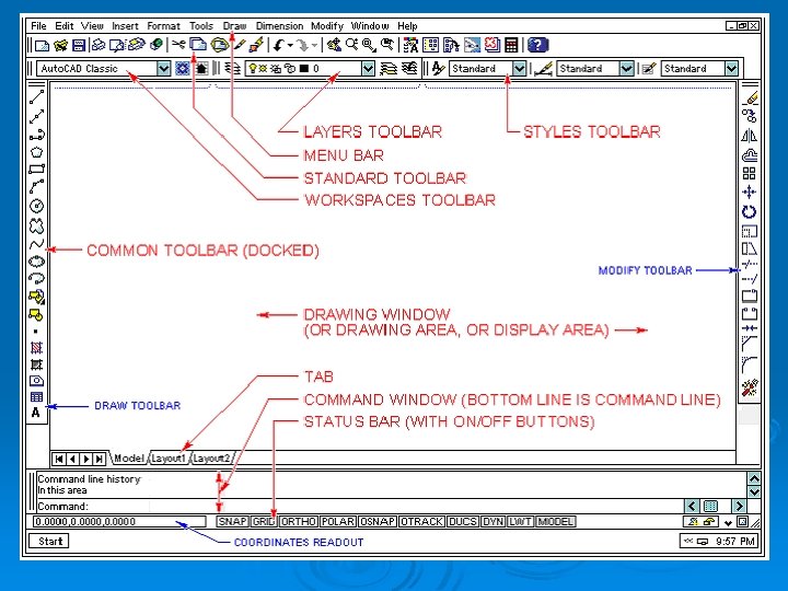
Selecting and using commands Select commands using any of these methods: Ø Choose a command from a menu. Ø Click a tool in a toolbar. Ø Type the command in the command bar.
Getting online Help You can display online Help in any of these ways: Ø On the Standard toolbar, click Help. Ø Press F 1. Ø Choose a command from the Help menu. Ø Click Help in a dialog box. Ø Type help in the command bar.
Saving a drawing To save a drawing, use one of the following methods: Ø On the Standard toolbar, click Save. Ø Choose File > Save. Ø Type save and then press Enter. Ø Type qsave and then press Enter.
Commonly used function Keys Comman d Typed entry Description F 1 Help HELP Starts online Help. F 2 Prompt History Window PMTHIS T Turns the Prompt History window on and off. F 3 Entity Snap ESNAP Turns entity snaps on and off. F 5 Isometric Plane ISOPLAN E Switches the isometric plane between Top, Right, and Left. F 6 Coordina te COORDI NATE Switches coordinate display between On, Off, and Angle/Distance. F 7 Grid GRID Turns the reference grid on and off. F 8 Orthogon al ORTHO GONAL Switches the orthogonal mode on and off. F 9 Snap SNAP Turns snap Settings on and off. F 10 Status Bar STATBA R Turns the status bar on and off.
Drawing Limits: Ø Drawing limits are used to set the boundaries of the drawing. The drawing boundaries are usually set to match the size of a sheet of drawing paper. This means that when the drawing is plotted and a hard copy is made, it will fit on the drawing paper.
Standard Drawing Sheet Sizes are In millimeters A 4 A 3 A 2 A 1 A 0 210 X 297 X 420 X 594 X 841 X 1189 In Architectural (USA) A B C D E 9 X 12 12 X 18 18 X 24 24 X 36 36 X 48
Generally, A 4 and A are commonly used. Ø In millimeters for A 4 type in command prompt 297, 210; Press Enter Ø In Architectural (USA) for A type in command prompt 12, 9; Press Enter
Engineering Graphics + CAD Ø Computer-aided design (CAD) : CAD refers to the use of computer tools to assist engineers, architects and other design professionals in their design activities. CAD applications in various fields of engineering are given here: Ø Ø Ø Mechanical : Design of machine elements, CNC machine tools, Robotics etc. Automotive : Kinematics, Hydraulics, Steering. Electrical : Circuit layout, Panel design, Control system. Electronics : Schematic diagrams of PCs, ICs etc. Communication : Communication network, Satellite transmitting pictures, T. V. telecasting
Engineering Graphics + CAD Ø Civil: Mapping, Contour plotting, Building drawing, Structural design Ø Architectural: Town planning, Interior decorations, Modelling, Multi- Storeyed complex. Ø Aerospace : Design of spacecraft, Flight simulator, lofting etc.
Coordinate systems: 1. Absolute Coordinate systems (X, Y) 2. Relative Coordinate systems (@ X distance, Y distance ) 3. Relative polar coordinate system ( @ distance < angel)
Absolute Coordinate systems (X, Y) 5, 5 3, 3 7, 3 Command: line Start of line: 3, 3 Angle/length/<end point>: 7, 3 Angle/length/Follow/undo/<end point>: 5, 5 Angle/length/Follow/close/undo/<end point>: c
Relative Rectangular coordinate system @ x-displacement, Y-displacement
Ø Command: : LINE or L <- Start point of line: (pick P 1) Angle/Length/: @5, 0 <Angle/Length/Follow/Undo/: @0, 5 <Angle/Length/Follow/Undo/: @-5, 0 <Angle/Length/Follow/Undo/: @0, -5 <Angle/Length/Follow/Undo/: c <-
Relative polar coordinate system ( @ distance < angel)
Ø Command: : LINE or L <- Start point of line: (pick P 1) Angle/Length/: @5<0 <Angle/Length/Follow/Undo/: @5<90 <Angle/Length/Follow/Undo/: @5<180 <Angle/Length/Follow/Undo/: @5<270 <Angle/Length/Follow/Undo/: c <-
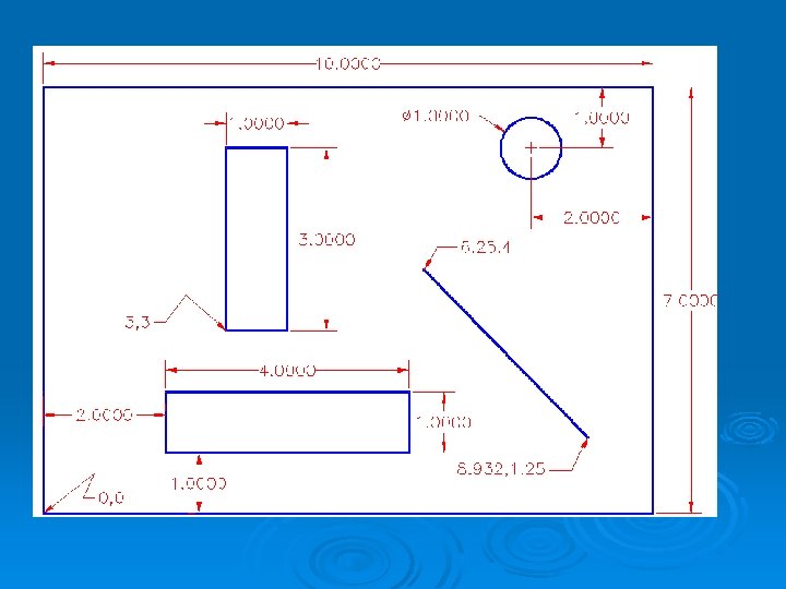
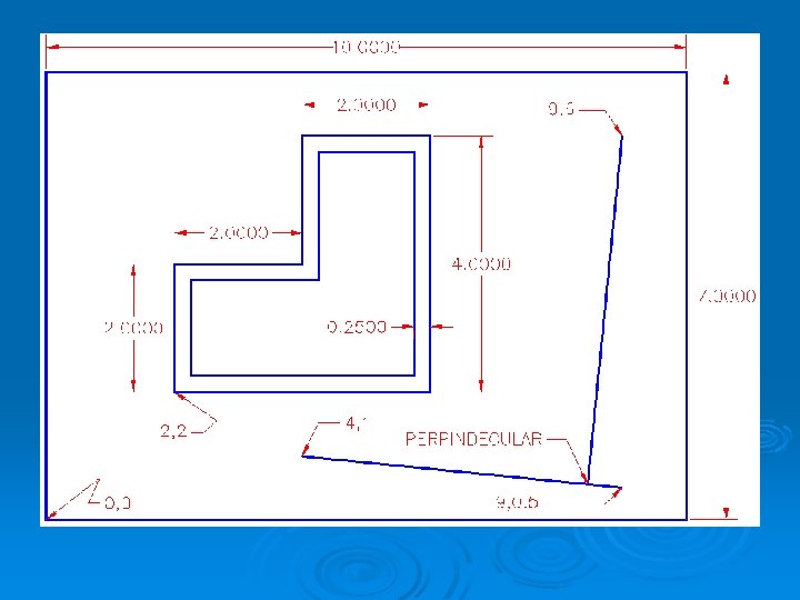
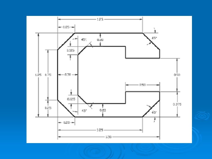
Dimensioning should follow these guidelines. Ø Accuracy: correct values must be given. Ø Clearness: dimensions must be placed in appropriate positions. Ø Completeness: nothing must be left out, and nothing duplicated. Ø Readability: the appropriate line quality must be used for legibility.
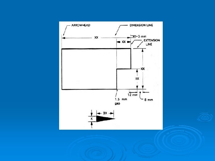
The Basics: Definitions and Dimensions The dimension line is a thin line, broken in the middle to allow the placement of the dimension value, with arrowheads at each end Ø An arrowhead is approximately 3 mm long and 1 mm wide. That is, the length is roughly three times the width. Ø An extension line extends a line on the object to the dimension line. The first dimension line should be approximately 12 mm (0. 6 in) from the object. Extension lines begin 1. 5 mm from the Ø
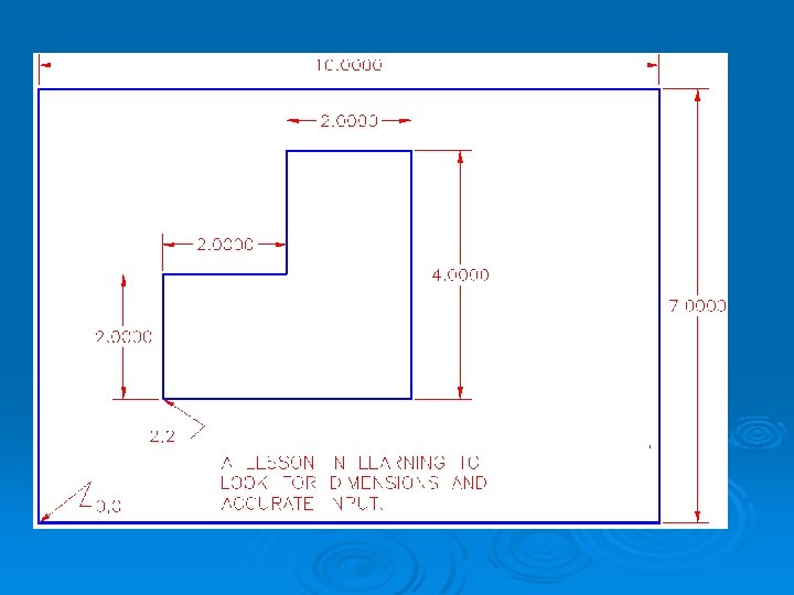
Commands to draw the diagram: • line • 0, 0 • 100, 70 • 0, 0 • Esc • line • 0, 0 • 20, 20 • 60, 60 continue. . . • 40, 60 • 40, 40 • 20, 20 • Esc