
Engineering Drawing MEC 01 D ELLIPSE PROBLEM DRAW
Engineering Drawing MEC 01 D
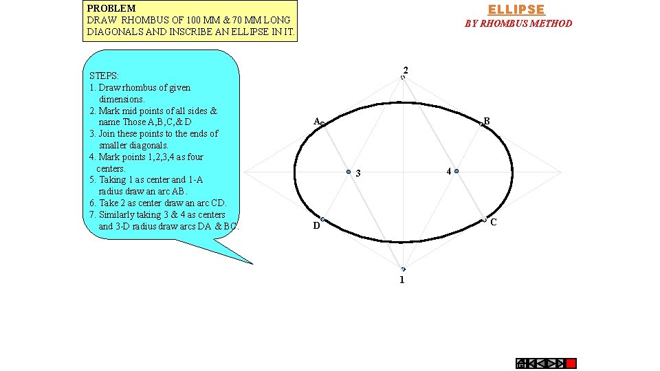
ELLIPSE PROBLEM DRAW RHOMBUS OF 100 MM & 70 MM LONG DIAGONALS AND INSCRIBE AN ELLIPSE IN IT. STEPS: 1. Draw rhombus of given dimensions. 2. Mark mid points of all sides & name Those A, B, C, & D 3. Join these points to the ends of smaller diagonals. 4. Mark points 1, 2, 3, 4 as four centers. 5. Taking 1 as center and 1 -A radius draw an arc AB. 6. Take 2 as center draw an arc CD. 7. Similarly taking 3 & 4 as centers and 3 -D radius draw arcs DA & BC. BY RHOMBUS METHOD 2 A B 4 3 C D 1
Projection of points
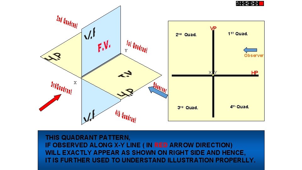
VP 2 nd Quad. 1 ST Quad. Y Observer HP X Y X 3 rd Quad. 4 th Quad. THIS QUADRANT PATTERN, IF OBSERVED ALONG X-Y LINE ( IN RED ARROW DIRECTION) WILL EXACTLY APPEAR AS SHOWN ON RIGHT SIDE AND HENCE, IT IS FURTHER USED TO UNDERSTAND ILLUSTRATION PROPERLLY.
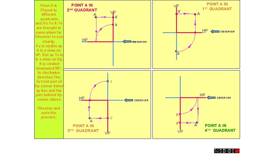
POINT A IN Point A is ND Placed In 2 QUADRANT different A quadrants and it’s Fv & Tv are brought in same plane for Observer to see HP clearly. Fv is visible as it is a view on VP. But as Tv is is a view on Hp, it is rotated downward 900, In clockwise direction. The In front part of Hp comes below xy line and the part behind Vp HP comes above. Observe and note the process. A POINT A IN RD 3 QUADRANT POINT A IN 1 ST QUADRANT VP a’ A a HP OBSERVER a’ a a’ VP OBSERVER VP A POINT A IN 4 TH QUADRANT

PROJECTIONS OF A POINT IN FIRST QUADRANT. POINT A ABOVE HP & INFRONT OF VP For Tv PICTORIAL PRESENTATION a’ A Y X POINT A IN HP & INFRONT OF VP POINT A ABOVE HP & IN VP For a’ A For Y Fv Fv Y a’ a X X a For Tv PICTORIAL PRESENTATION A a For ORTHOGRAPHIC PRESENTATIONS OF ALL ABOVE CASES. Fv above xy, Tv below xy. VP Fv above xy, Tv on xy. Fv on xy, Tv below xy. VP VP a’ a’ X Y X a Y a’ X a a HP HP HP Y Fv
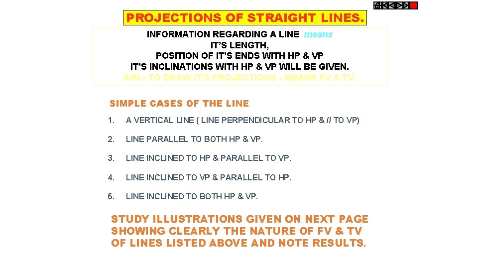
PROJECTIONS OF STRAIGHT LINES. INFORMATION REGARDING A LINE means IT’S LENGTH, POSITION OF IT’S ENDS WITH HP & VP IT’S INCLINATIONS WITH HP & VP WILL BE GIVEN. AIM: - TO DRAW IT’S PROJECTIONS - MEANS FV & TV. SIMPLE CASES OF THE LINE 1. A VERTICAL LINE ( LINE PERPENDICULAR TO HP & // TO VP) 2. LINE PARALLEL TO BOTH HP & VP. 3. LINE INCLINED TO HP & PARALLEL TO VP. 4. LINE INCLINED TO VP & PARALLEL TO HP. 5. LINE INCLINED TO BOTH HP & VP. STUDY ILLUSTRATIONS GIVEN ON NEXT PAGE SHOWING CLEARLY THE NATURE OF FV & TV OF LINES LISTED ABOVE AND NOTE RESULTS.
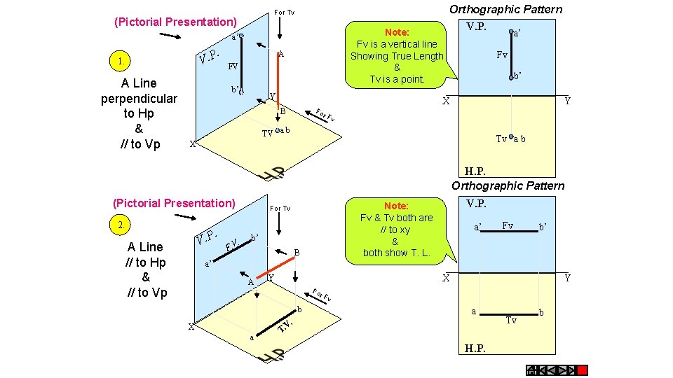
For Tv (Pictorial Presentation) Note: Fv is a vertical line Showing True Length & Tv is a point. a’ V. P 1. A Line perpendicular to Hp & // to Vp . A FV b’ Y a’ Fv b’ X Fo r. F B Orthographic Pattern V. P. Y v TV a b Tv a b X H. P. Orthographic Pattern (Pictorial Presentation) 2. . P. V A Line // to Hp & // to Vp . F. V V. P. Note: Fv & Tv both are // to xy & both show T. L. For Tv b’ B a’ Fv b’ a’ A X Y Y Fo r. F v b a V. X a T. H. P. Tv b
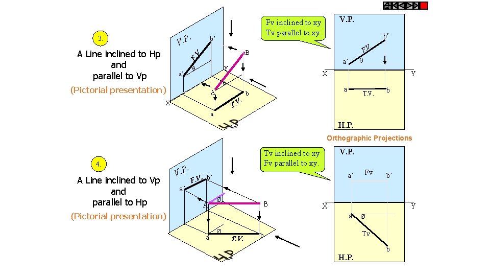
. V. P 3. b’ b’. F. V B F. V. A Line inclined to Hp and parallel to Vp V. P. Fv inclined to xy Tv parallel to xy. a’ Y X (Pictorial presentation) a’ A . Y a b T. V X a H. P. Orthographic Projections 4. A Line inclined to Vp and parallel to Hp . V. P a’ V. P. Tv inclined to xy Fv parallel to xy. a’ . b’ F. V A Ø B (Pictorial presentation) Ø T. V. b’ X Y a a Fv Ø Tv b H. P. b
- Slides: 9