
Engineer Training XL 1200 Electric Engineer Training Confidential
- Slides: 13
Engineer Training XL 1200 Electric
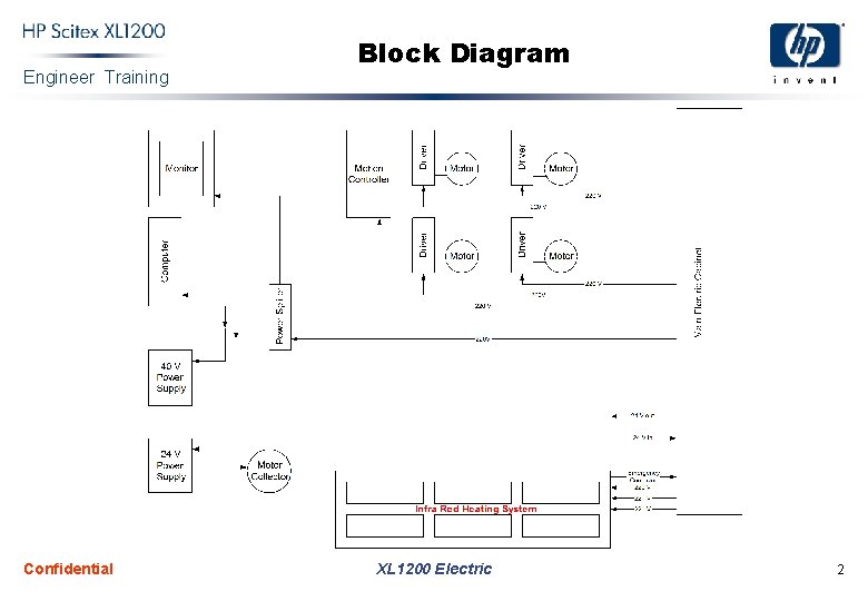
Engineer Training Confidential Block Diagram XL 1200 Electric 2
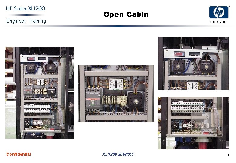
Engineer Training Confidential Open Cabin XL 1200 Electric 3
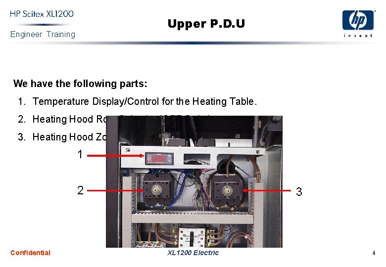
Upper P. D. U Engineer Training We have the following parts: 1. Temperature Display/Control for the Heating Table. 2. Heating Hood Row Selection/OFF Switch 3. Heating Hood Zone Selection Switch. 1 2 Confidential 3 XL 1200 Electric 4
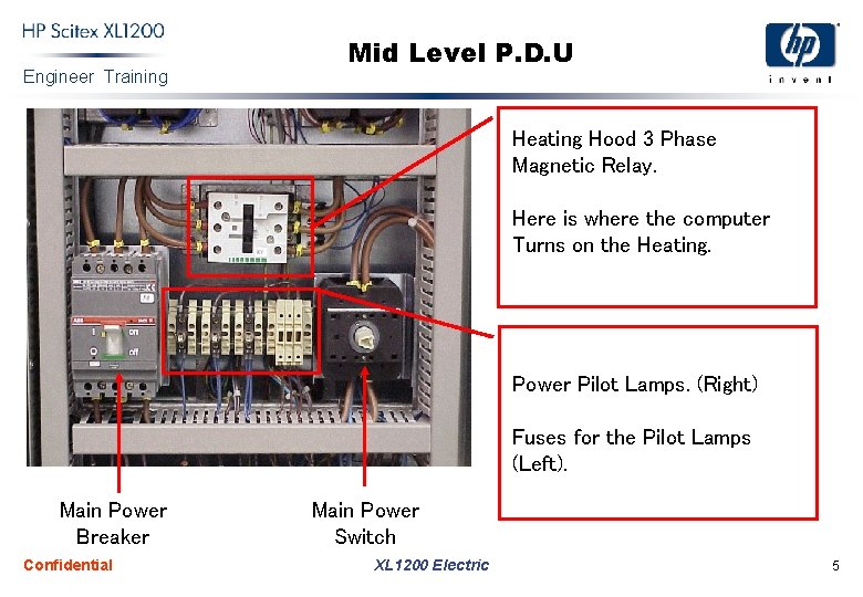
Engineer Training Mid Level P. D. U Heating Hood 3 Phase Magnetic Relay. Here is where the computer Turns on the Heating. Power Pilot Lamps. (Right) Fuses for the Pilot Lamps (Left). Main Power Breaker Confidential Main Power Switch XL 1200 Electric 5
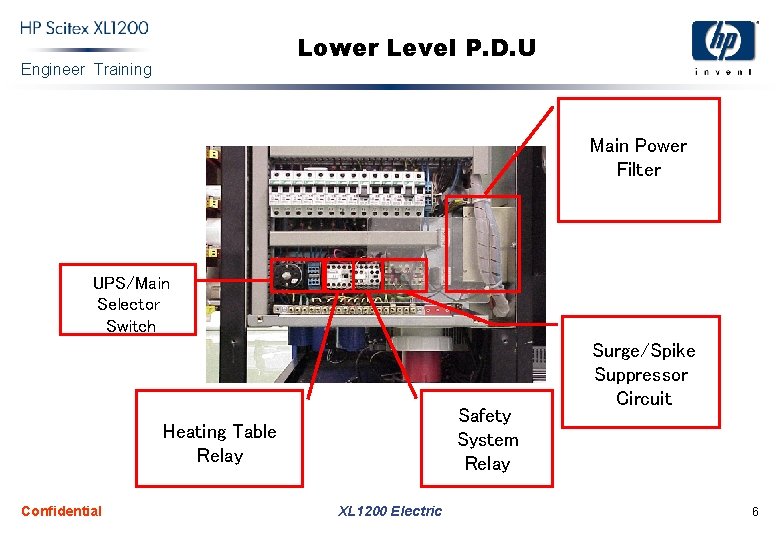
Lower Level P. D. U Engineer Training Main Power Filter UPS/Main Selector Switch Safety System Relay Heating Table Relay Confidential XL 1200 Electric Surge/Spike Suppressor Circuit 6
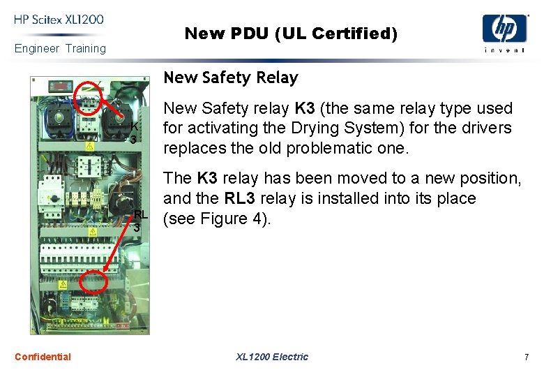
New PDU (UL Certified) Engineer Training New Safety Relay K 3 RL 3 Confidential New Safety relay K 3 (the same relay type used for activating the Drying System) for the drivers replaces the old problematic one. The K 3 relay has been moved to a new position, and the RL 3 relay is installed into its place (see Figure 4). XL 1200 Electric 7
Engineer Training Confidential New PDU (UL Certified) XL 1200 Electric 8
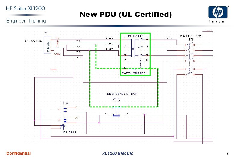
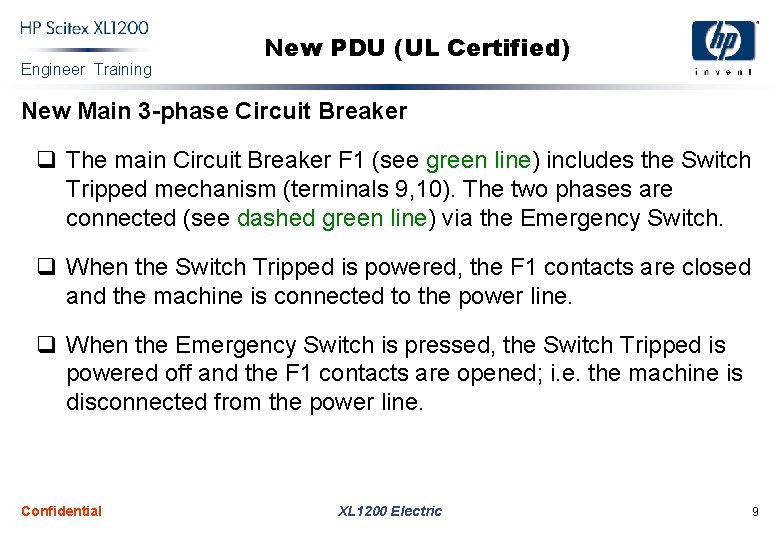
Engineer Training New PDU (UL Certified) New Main 3 -phase Circuit Breaker q The main Circuit Breaker F 1 (see green line) includes the Switch Tripped mechanism (terminals 9, 10). The two phases are connected (see dashed green line) via the Emergency Switch. q When the Switch Tripped is powered, the F 1 contacts are closed and the machine is connected to the power line. q When the Emergency Switch is pressed, the Switch Tripped is powered off and the F 1 contacts are opened; i. e. the machine is disconnected from the power line. Confidential XL 1200 Electric 9
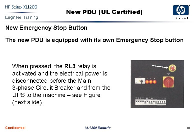
Engineer Training New PDU (UL Certified) New Emergency Stop Button The new PDU is equipped with its own Emergency Stop button When pressed, the RL 3 relay is activated and the electrical power is disconnected before the Main 3 -phase Circuit Breaker and from the UPS to the machine – see Figure (next slide). Confidential XL 1200 Electric 10
Engineer Training Confidential Main Safety - PDU XL 1200 Electric To UPS 11
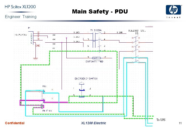
Engineer Training Main Safety - PDU The green dash line marks the circuit UPS Emergency Switch RL 3 coil UPS. When the Emergency Switch is pressed, this circuit is opened. The cyan dot line specifies the circuit UPS RL 3 contacts Drivers Left Cabinet (PC, Power Supplies) UPS. When the Emergency Switch is pressed, this circuit is opened. The magenta dot line specifies the self-sustain loop for holding the RL 3 powered in case of general electric failure (i. e. Switch Tripped is not powered and the green circuit is opened). Confidential XL 1200 Electric 12
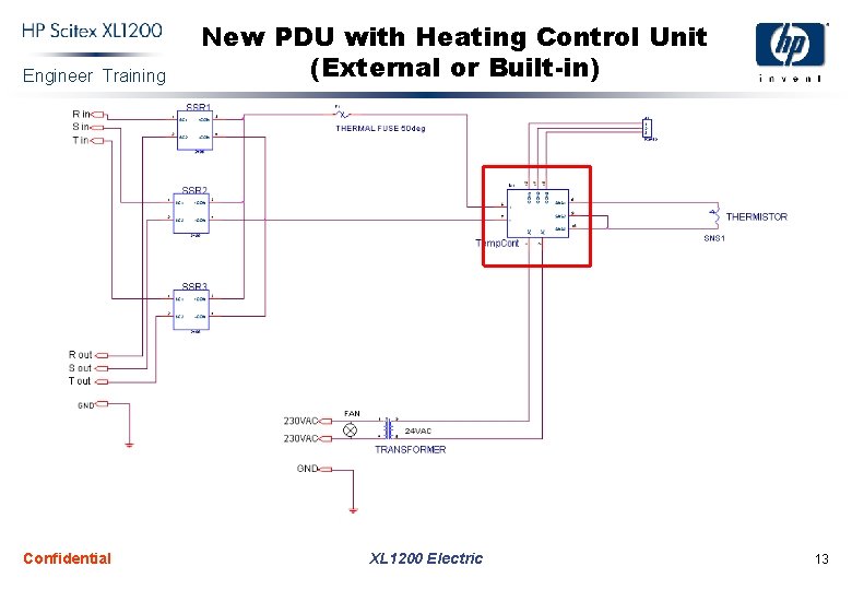
Engineer Training Confidential New PDU with Heating Control Unit (External or Built-in) XL 1200 Electric 13