
Engine assembly Before final cleaning Remove all sharp

Engine assembly Before final cleaning • Remove all sharp edges created by machining Combustion chamber Crankshaft oil holes Top & bottom of cylinders Oil pump gears • Clean all internal & external threads Chamfer top of bolt holes Use tap or die for restoring threads Copyright 2003 Gary Lewis – Dave Capitolo
Engine assembly Before final cleaning • Check lifter bores for rust & burrs Use glaze breaker if necessary • Check cam bores for burrs Could distort cam bearings if not deburred
Engine assembly Final cleaning • Only after all machining is done • Use detergent hot tank • Insufficient cleaning results in. . . Piston ring wear Bearing wear Valve stem wear
Engine assembly Final cleaning • Coat cylinders & decks with clean oil to prevent rust • Coat valves, seats, & decks with clean oil
Engine assembly Assembling cylinder heads • Guides must be clean & lubricated • Install valves with oil • Protect seals with plastic sleeve on valve • Check cam rotation on OHC heads
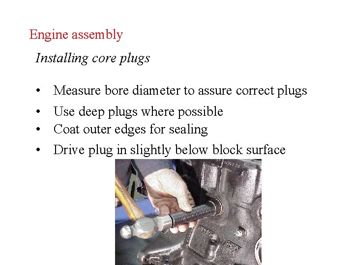
Engine assembly Installing core plugs • Measure bore diameter to assure correct plugs • Use deep plugs where possible • Coat outer edges for sealing • Drive plug in slightly below block surface
Engine assembly Sealing coolant, lubricants, & combustion • Typical cooling system is 15 PSI @ 230°F • Typical oil pressure range is 20 -80 PSI • Gasket must not restrict flow • Fire rings protect gasket material & cyl pressure
Engine assembly Chemical sealers • Sometimes used in place of gaskets • Silicone sealers (RTV) are flexible & temp resistant • Anaerobic sealers – Absence of air
Engine assembly Head gaskets • Metal-asbestos replaced with ceramic laminate • Composite core copper Good compressibility, low compression, 60 AA • Composite core steel Heat resistant, high compression, 60 AA • Coated gaskets Resin, polymer, better sealing of fluids • MLS (Multi layer steel) For dissimilar metals, 15 -20 AA
Engine assembly Head gaskets • Stainless steel face On one side for high cylinder head temps, GM diesels • Embossed steel Improved heat transfer, ridges provide crush for sealing, high compression, 30 -50 AA • No-retorque Polymer coated, printed with silicone for low clamping force areas
Engine assembly Gaskets • Cork used on valve covers, lifter covers, oil pans Stretches & shrinks • Synthetic rubber Compressible, does not wick, resists heat
Engine assembly Crankshaft seals • Rope type seals must be fitted • Lip type seals Lips face the oil • Nitril & neoprene are common • Viton withstands loads & heat
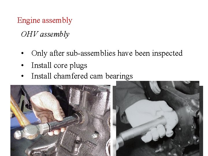
Engine assembly OHV assembly • Only after sub-assemblies have been inspected • Install core plugs • Install chamfered cam bearings
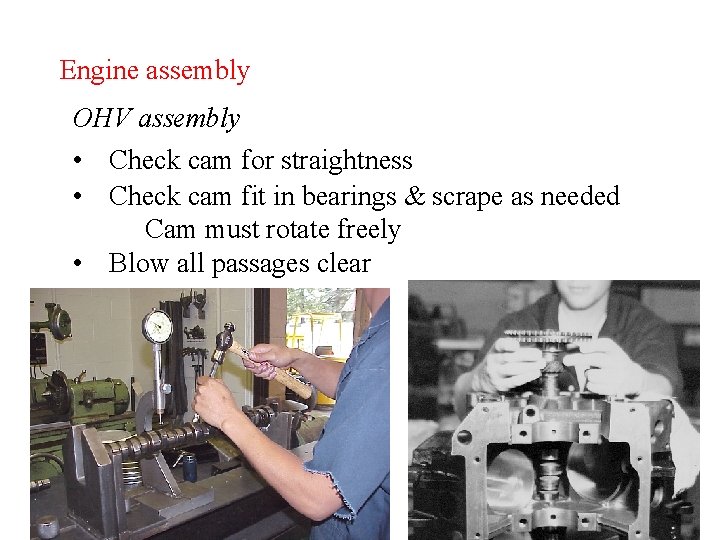
Engine assembly OHV assembly • Check cam for straightness • Check cam fit in bearings & scrape as needed Cam must rotate freely • Blow all passages clear
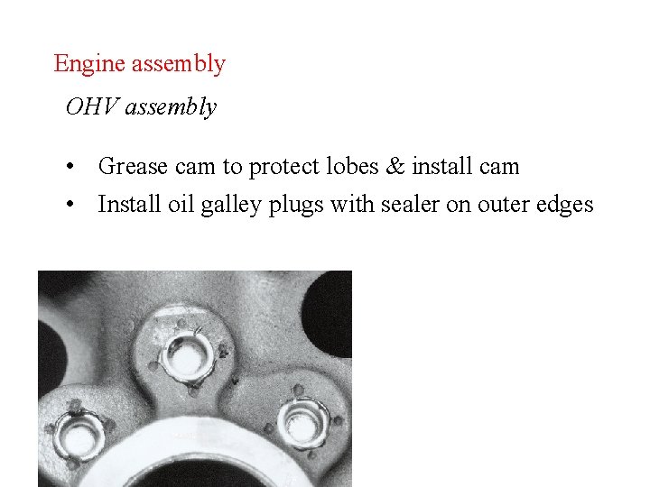
Engine assembly OHV assembly • Grease cam to protect lobes & install cam • Install oil galley plugs with sealer on outer edges
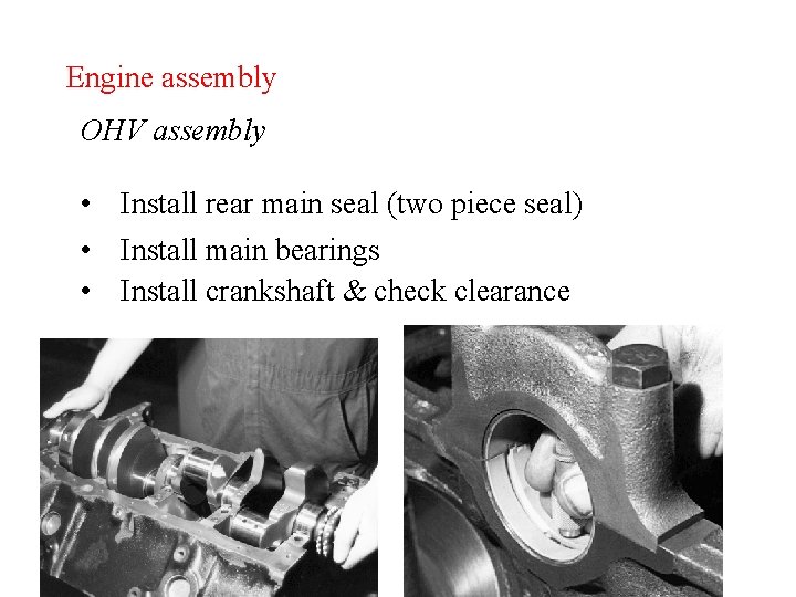
Engine assembly OHV assembly • Install rear main seal (two piece seal) • Install main bearings • Install crankshaft & check clearance
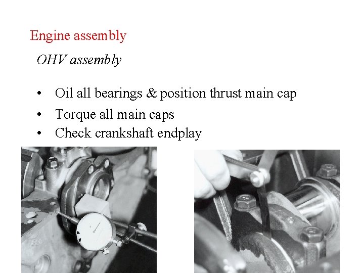
Engine assembly OHV assembly • Oil all bearings & position thrust main cap • Torque all main caps • Check crankshaft endplay
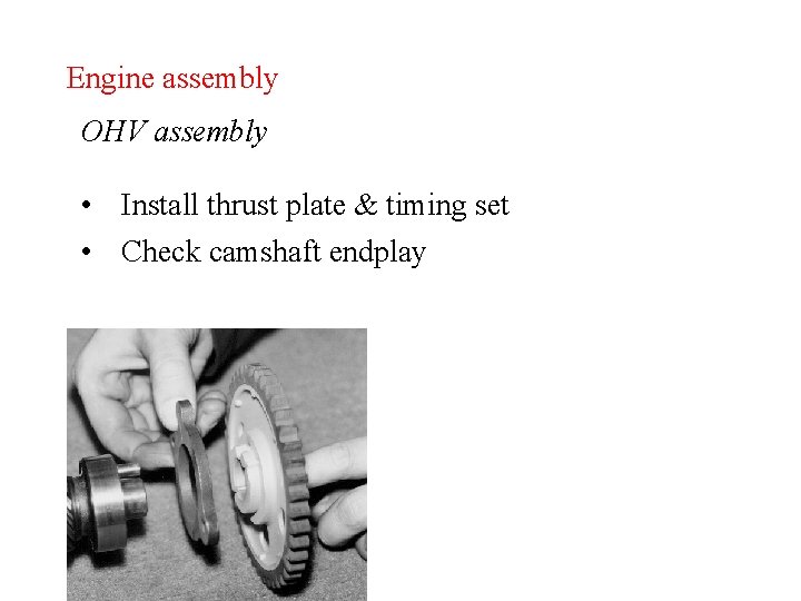
Engine assembly OHV assembly • Install thrust plate & timing set • Check camshaft endplay
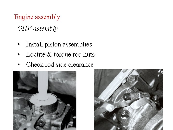
Engine assembly OHV assembly • Install piston assemblies • Loctite & torque rod nuts • Check rod side clearance
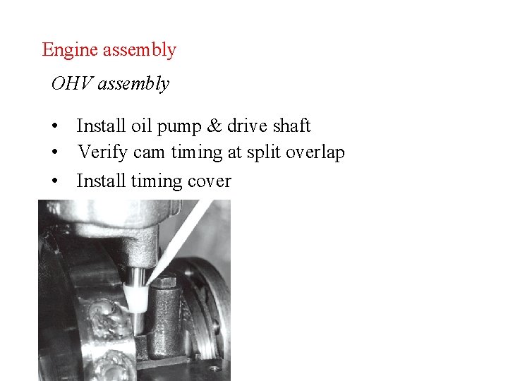
Engine assembly OHV assembly • Install oil pump & drive shaft • Verify cam timing at split overlap • Install timing cover
Engine assembly OHV assembly • • Install oil pan Torque heads onto block Install rocker arms & pushrods Adjust valves & test
Engine assembly OHC assembly differences • • Balance shaft bearings Crank & cam must be set to TDC before installation Some timing covers are installed before head or pan Timing belts and covers are installed last
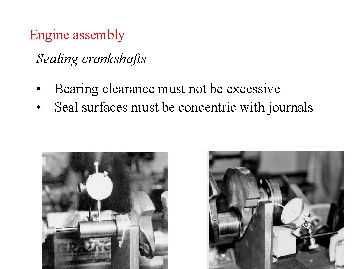
Engine assembly Sealing crankshafts • Bearing clearance must not be excessive • Seal surfaces must be concentric with journals
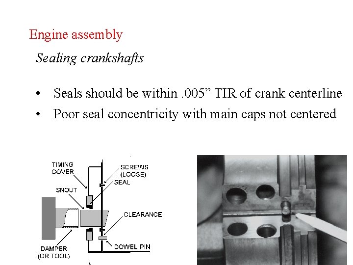
Engine assembly Sealing crankshafts • Seals should be within. 005” TIR of crank centerline • Poor seal concentricity with main caps not centered
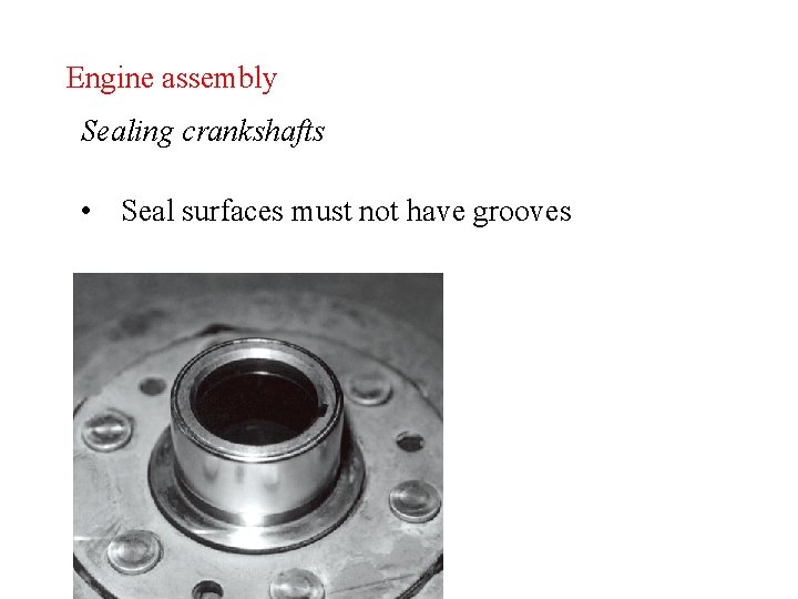
Engine assembly Sealing crankshafts • Seal surfaces must not have grooves
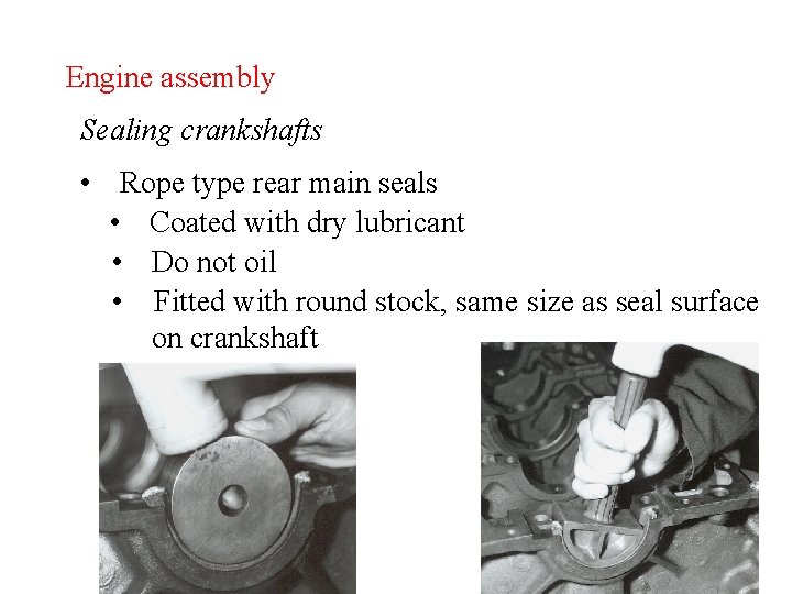
Engine assembly Sealing crankshafts • Rope type rear main seals • Coated with dry lubricant • Do not oil • Fitted with round stock, same size as seal surface on crankshaft
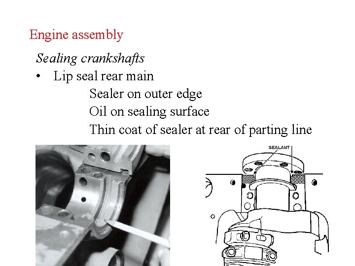
Engine assembly Sealing crankshafts • Lip seal rear main Sealer on outer edge Oil on sealing surface Thin coat of sealer at rear of parting line
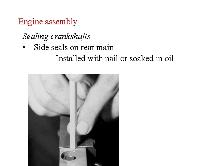
Engine assembly Sealing crankshafts • Side seals on rear main Installed with nail or soaked in oil
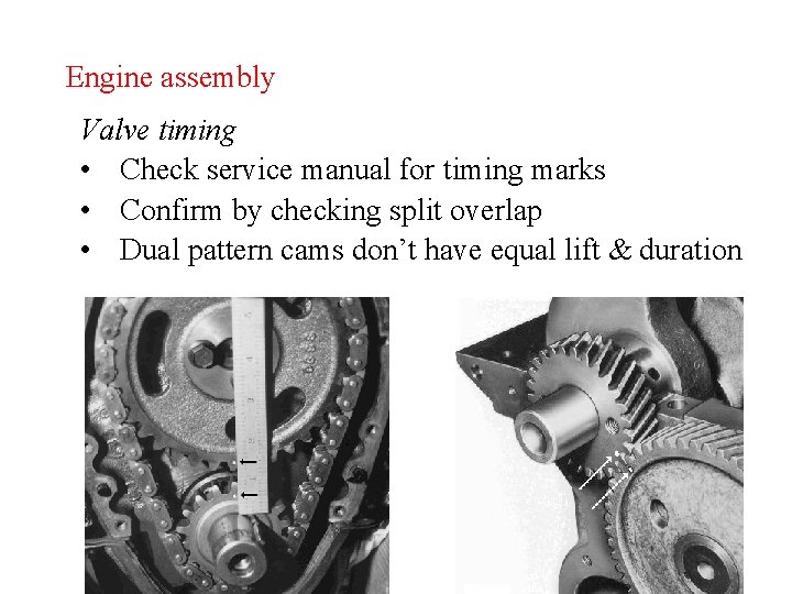
Engine assembly Valve timing • Check service manual for timing marks • Confirm by checking split overlap • Dual pattern cams don’t have equal lift & duration
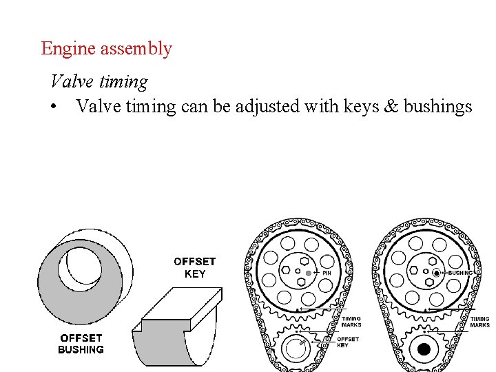
Engine assembly Valve timing • Valve timing can be adjusted with keys & bushings
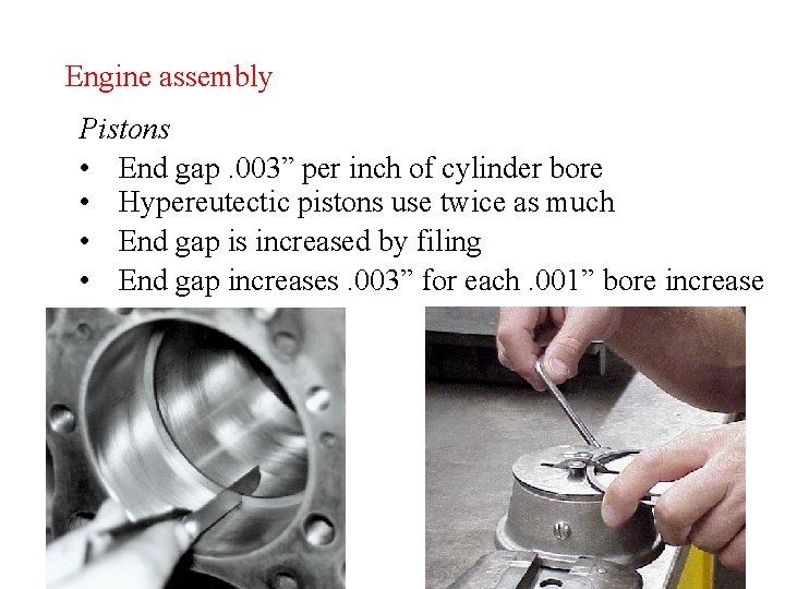
Engine assembly Pistons & rings • End gap. 003” per inch of cylinder bore • Hypereutectic pistons use twice as much • End gap is increased by filing • End gap increases. 003” for each. 001” bore increase
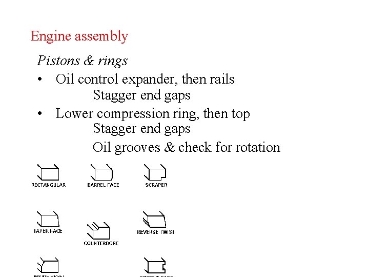
Engine assembly Pistons & rings • Oil control expander, then rails Stagger end gaps • Lower compression ring, then top Stagger end gaps Oil grooves & check for rotation
Engine assembly Piston types • Cast aluminum – OEM pistons • Forged aluminum – Stronger & better heat dissipation • Hypereutectic – High silicon content Lighter Good wear characteristics Tighter clearances due to low expansion rate Requires more ring end gap
Engine assembly Piston skirts • Slipper skirts – Cam ground Clearance for counterweights Steel struts help piston expand with pin • Full skirt– Used in longer stroke engines • Barrel shaped skirt– Largest diameter is in the center
Engine assembly Before attaching heads to blocks • Surfaces clean and flat • Threads clean • Sharp edges de-burred • Alignment dowels installed • Check gasket direction Do not use sealer on coated gaskets • Look up torque specs & sequence
Engine assembly Attaching heads to blocks • Threads lubricated with oil or sealer • Torque in sequence in 3 steps • TTY bolts may need to be replaced
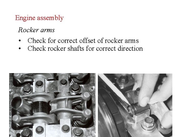
Engine assembly Rocker arms • Check for correct offset of rocker arms • Check rocker shafts for correct direction
Engine assembly Valve adjustment • Non-hydraulic valve trains Piston at TDC, compression Adjust valves that are closed & rotate engine • Adjustable hydraulic valve trains Zero lash plus pre-load Collapse lifter and set clearance • Non-adjustable hydraulic valve trains Torque to specs
Engine assembly Pre-oiling • Push rod engine Install lifters Rotate oil pump with speed handle • Crank driven oil pumps Pre-lubricator used to pre-oil engines • Assemble oil pump with grease for priming • Crank engine with no spark plugs, fuel, or ignition
Engine assembly Run-in stand • • • Oil pressure & circulation Compression Noises Gaskets & seals Lifter rotation
- Slides: 40