ENERGY STAR Qualified Homes HVAC SYSTEM QUALITY INSTALLATION


")
")
")


- Slides: 170
ENERGY STAR Qualified Homes HVAC SYSTEM QUALITY INSTALLATION RATER CHECKLIST 1
ENERGY STAR® QUALIFIED HOMES HVAC SYSTEM QUALITY INSTALLATION RATER CHECKLIST TABLE OF CONTENTS Section 1. Review of HVAC System Quality Installation Contractor Checklist 2 Section 2. Duct Quality Installation - Applies to All Heating, Cooling, Ventilation, Exhaust, and Pressure Balancing Ducts Section 3. Duct Insulation - Applies to All Heating, Cooling, Supply Ventilation, and Pressure Balancing Ducts 12 HVAC System Quality Installation Rater Checklist
ENERGY STAR® QUALIFIED HOMES HVAC SYSTEM QUALITY INSTALLATION RATER CHECKLIST TABLE OF CONTENTS Section 4. Duct Leakage - Applies to All Heating, Cooling, and Balanced Ventilation Ducts Section 5. Whole-building Delivered Ventilation Section 6. Controls Section 7. Ventilation Air Inlets & Ventilation Source HVAC System Quality Installation Rater Checklist
ENERGY STAR® QUALIFIED HOMES HVAC SYSTEM QUALITY INSTALLATION RATER CHECKLIST TABLE OF CONTENTS Section 8. Local Mechanical Exhaust Section 9. Ventilation & Exhaust Fan Ratings (Exemptions for HVAC and Remote. Mounted Fans) 30 Section 10. Combustion Appliances Section 11. Filtration HVAC System Quality Installation Rater Checklist
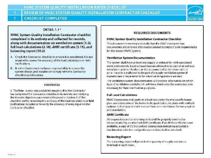
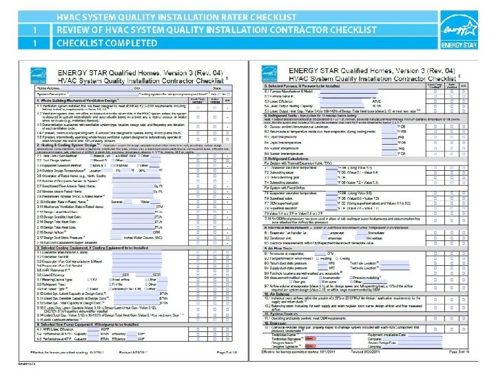
ENERGY STAR® QUALIFIED HOMES HVAC SYSTEM QUALITY INSTALLATION RATER CHECKLIST SECTION 1. REVIEW OF HVAC SYSTEM QUALITY INSTALLATION CONTRACTOR CHECKLIST 2 1. 1. HVAC System Quality Installation Contractor checklist completed in its entirety and collected for records, along with documentation on ventilation system (1. 3), full load calculations (2. 18), AHRI certificate (3. 15), and balancing report (10. 2). HVAC System Quality Installation Rater Checklist
ENERGY STAR® QUALIFIED HOMES HVAC SYSTEM QUALITY INSTALLATION RATER CHECKLIST SECTION 1. REVIEW OF HVAC SYSTEM QUALITY INSTALLATION CONTRACTOR CHECKLIST 1. 2 Review the following parameters related to system cooling design, selection, and installation from the HVAC Contractor checklist (Contractor checklist item # indicated in parenthesis): HVAC System Quality Installation Rater Checklist
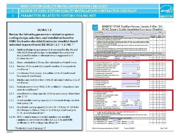
ENERGY STAR® QUALIFIED HOMES HVAC SYSTEM QUALITY INSTALLATION RATER CHECKLIST SECTION 1. REVIEW OF HVAC SYSTEM QUALITY INSTALLATION CONTRACTOR CHECKLIST 2 1. 2 Review the following parameters related to system cooling design, selection, and installation from the HVAC Contractor checklist (Contractor checklist item # indicated in parenthesis): 1. 2. 1 Outdoor design temperatures (2. 4) are equal to the 1% and 99% ACCA Manual J design temperatures for contractor-designated design location 4 HVAC System Quality Installation Rater Checklist
ENERGY STAR® QUALIFIED HOMES HVAC SYSTEM QUALITY INSTALLATION RATER CHECKLIST SECTION 1. REVIEW OF HVAC SYSTEM QUALITY INSTALLATION CONTRACTOR CHECKLIST 2 1. 2. 3 1. 2. 4 1. 2. 5 1. 2. 6 Home orientation (2. 5) matches orientation of rated home Number of Occupants (2. 6) equals number of occupants in rated home 5 Conditioned floor area (2. 7) is within ± 10% of conditioned floor area of rated home Window area (2. 8) is within ± 10% of calculated window area of rated home Predominant window SHGC (2. 9) is within 0. 1 of predominant value in rated home 6 HVAC System Quality Installation Rater Checklist
ENERGY STAR® QUALIFIED HOMES HVAC SYSTEM QUALITY INSTALLATION RATER CHECKLIST SECTION 1. REVIEW OF HVAC SYSTEM QUALITY INSTALLATION CONTRACTOR CHECKLIST 2 1. 2. 7 1. 2. 8 1. 2. 9 1. 2. 10 Listed latent cooling capacity (3. 10) exceeds design latent heat gain (2. 12) Listed sensible cooling capacity (3. 11) exceeds design sensible heat gain (2. 13) Listed total cooling capacity (3. 12) is 95 -115% (or 95125% for Heat Pumps in Climate Zones 4 -8) of design total heat gain (2. 14), or next nominal size 7 HVAC manufacturer and model numbers on installed equipment, contractor checklist (3. 1, 3. 3, 5. 1), and AHRI certificate or OEM catalog data all match 8 HVAC System Quality Installation Rater Checklist
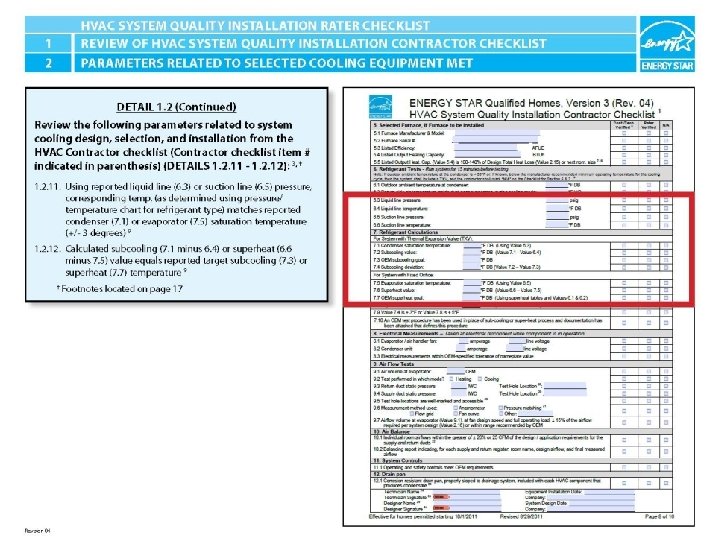
ENERGY STAR® QUALIFIED HOMES HVAC SYSTEM QUALITY INSTALLATION RATER CHECKLIST SECTION 1. REVIEW OF HVAC SYSTEM QUALITY INSTALLATION CONTRACTOR CHECKLIST 2 1. 2. 11 1. 2. 12 Using reported liquid line (6. 3) or suction line (6. 5) pressure, corresponding temp. (as determined using pressure/temperature chart for refrigerant type) matches reported condenser (7. 1) or evaporator (7. 5) saturation temperature (+/- 3 degrees) 9 Calculated subcooling (7. 1 minus 6. 4) or superheat (6. 6 minus 7. 5) value equals reported target subcooling (7. 3) or superheat (7. 7) temperature 9 HVAC System Quality Installation Rater Checklist
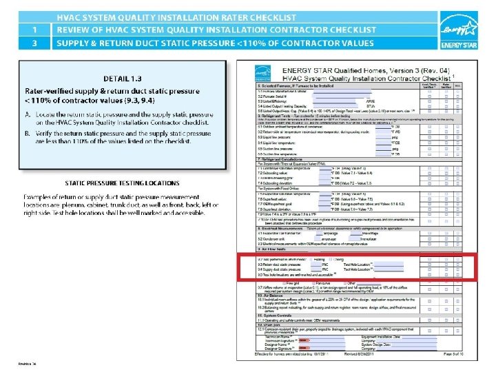
ENERGY STAR® QUALIFIED HOMES HVAC SYSTEM QUALITY INSTALLATION RATER CHECKLIST SECTION 1. REVIEW OF HVAC SYSTEM QUALITY INSTALLATION CONTRACTOR CHECKLIST 2 1. 3 Rater-verified supply & return duct static pressure<110% of contractor values (9. 3, 9. 4) HVAC System Quality Installation Rater Checklist
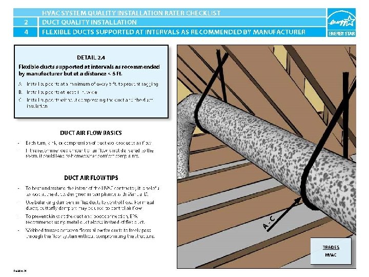
ENERGY STAR® QUALIFIED HOMES HVAC SYSTEM QUALITY INSTALLATION RATER CHECKLIST SECTION 2. DUCT QUALITY INSTALLATION - Applies to All Heating, Cooling, Ventilation, Exhaust, and Pressure Balancing Ducts 2. 1 Connections and routing of ductwork completed without kinks or sharp bends. 10 2. 2 No excessive coiled or looped flexible ductwork. 11 2. 3 Flexible ducts in unconditioned space not installed in cavities smaller than outer duct diameter; in conditioned space not installed in cavities smaller than inner duct diameter 2. 4 Flexible ducts supported at intervals as recommended by mfr. but at a distance < 5 ft.
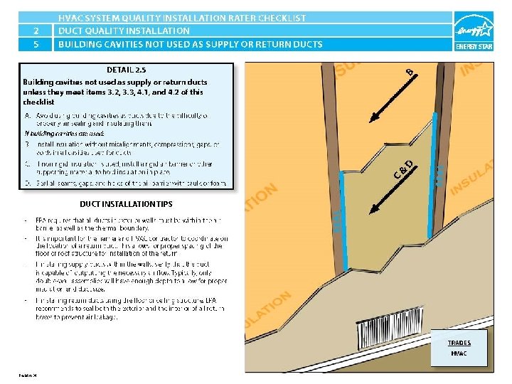
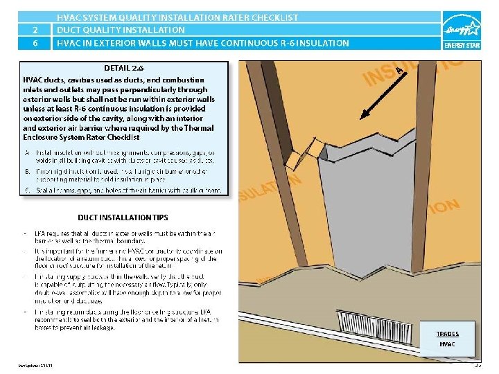
ENERGY STAR® QUALIFIED HOMES HVAC SYSTEM QUALITY INSTALLATION RATER CHECKLIST SECTION 2. DUCT QUALITY INSTALLATION - Applies to All Heating, Cooling, Ventilation, Exhaust, and Pressure Balancing Ducts 2. 5 Building cavities not used as supply or return ducts unless they meet items 3. 2, 3. 3, 4. 1, and 4. 2 of this checklist. 2. 6 HVAC ducts, cavities used as ducts, and combustion inlets and outlets may pass perpendicularly through exterior walls but shall not be run within exterior walls unless at least R-6 continuous insulation is provided on exterior side of the cavity, along with an interior and exterior air barrier where required by the Thermal Enclosure System Rater Checklist. HVAC System Quality Installation Rater Checklist
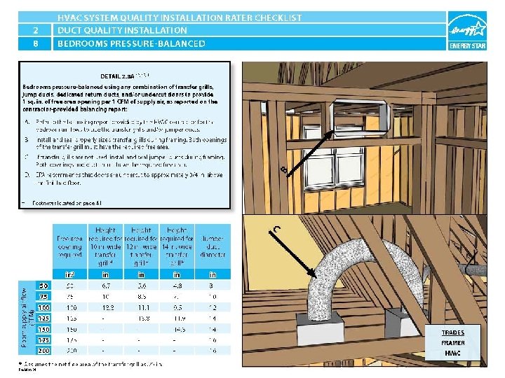
ENERGY STAR® QUALIFIED HOMES HVAC SYSTEM QUALITY INSTALLATION RATER CHECKLIST SECTION 2. DUCT QUALITY INSTALLATION 2. 7 Quantity & location of supply and return duct terminals match contractor balancing report. 2. 8 Bedrooms pressure-balanced using any combination of transfer grills, jump ducts, dedicated return ducts, and/or undercut doors to either: a) provide 1 sq. in. of free area opening per 1 CFM of supply air, as reported on the contractor-provided balancing report; or HVAC System Quality Installation Rater Checklist
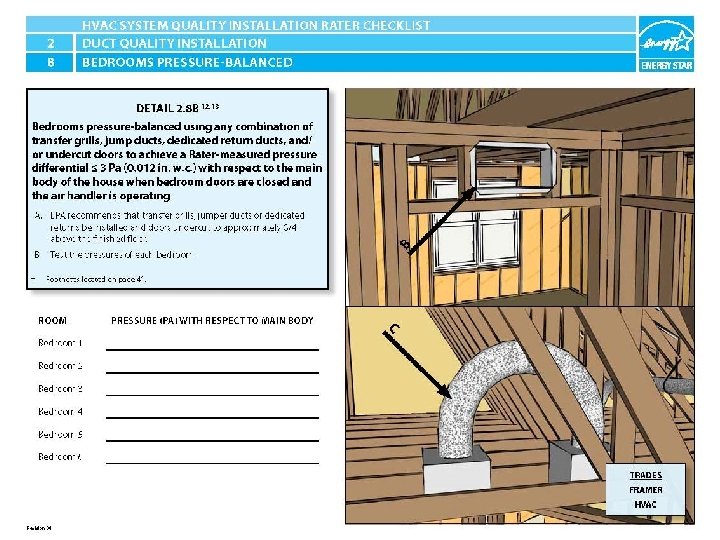
ENERGY STAR® QUALIFIED HOMES HVAC SYSTEM QUALITY INSTALLATION RATER CHECKLIST SECTION 2. DUCT QUALITY INSTALLATION b) achieve a Rater-measured pressure differential < 3 Pa (0. 012 in. w. c. ) with respect to the main body of the house when bedroom doors are closed and the air handler is operating. 12, 13 HVAC System Quality Installation Rater Checklist
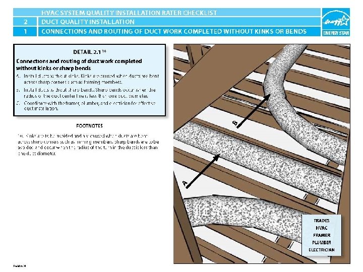
ENERGY STAR® QUALIFIED HOMES HVAC SYSTEM QUALITY INSTALLATION RATER CHECKLIST SECTION 2. DUCT QUALITY INSTALLATION 2. 1 Connections and routing of ductwork completed without kinks or sharp bends. 10 HVAC System Quality Installation Rater Checklist
2. 1 Connections and routing of ductwork completed without kinks or sharp bends. 9 CJ LD A Duct is kinked in cavity. Duct is run straight and supported properly. HVAC System Quality Installation Rater Checklist
2. 1 Connections and routing of ductwork completed without kinks or sharp bends. 9 CJ LD B Ducks crammed into cavity, kinked and sharply bent. Ducts are run straight and supported properly. HVAC System Quality Installation Rater Checklist
2. 1 Connections and routing of ductwork completed without kinks or sharp bends. 9 CJ LD C Excessive length of duct installed causing sharp bends. Fan housing was oriented in the correct direction to allow proper exhaust duct installation. HVAC System Quality Installation Rater Checklist
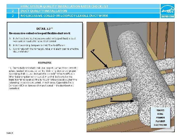
ENERGY STAR® QUALIFIED HOMES HVAC SYSTEM QUALITY INSTALLATION RATER CHECKLIST SECTION 2. DUCT QUALITY INSTALLATION 2. 2 No excessive coiled or looped flexible ductwork. 11
2. 2 No excessive coiled or looped flexible ductwork. 11 CJ LD A Excessive length of duct installed. Duct is run straight and supported properly. HVAC System Quality Installation Rater Checklist
2. 2 No excessive coiled or looped flexible ductwork. 11 CJ LD B No mechanical damper installed. Mechanical damper installed. HVAC System Quality Installation Rater Checklist
2. 2 No excessive coiled or looped flexible ductwork. 11 CJ LD C Excessive length of duct installed causing sharp bends. Fan housing was oriented in the correct direction to allow proper exhaust duct installation. HVAC System Quality Installation Rater Checklist
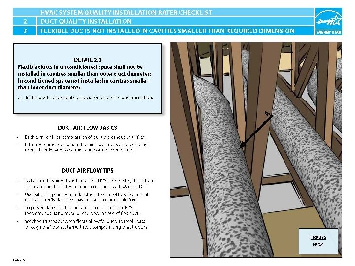
ENERGY STAR® QUALIFIED HOMES HVAC SYSTEM QUALITY INSTALLATION RATER CHECKLIST SECTION 2. DUCT QUALITY INSTALLATION 2. 3 Flexible ducts in unconditioned space not installed in cavities smaller than outer duct diameter; in conditioned space not installed in cavities smaller than inner duct diameter
2. 3 Flexible ducts in unconditioned space not installed in cavities smaller than outer duct diameter; in conditioned space not installed in cavities smaller than inner duct diameter CJ LD A Duct is compressed. Framing allowed ductwork to be properly installed without compression. HVAC System Quality Installation Rater Checklist
2. 3 Flexible ducts in unconditioned space not installed in cavities smaller than outer duct diameter; in conditioned space not installed in cavities smaller than inner duct diameter CJ LD A Recessed can light is compressing ductwork. Ducts properly installed without compression and appropriately supported. HVAC System Quality Installation Rater Checklist
2. 3 Flexible ducts in unconditioned space not installed in cavities smaller than outer duct diameter; in conditioned space not installed in cavities smaller than inner duct diameter CJ LD A Duct is compressed. Ducts properly installed without compression and appropriately supported. HVAC System Quality Installation Rater Checklist
ENERGY STAR® QUALIFIED HOMES HVAC SYSTEM QUALITY INSTALLATION RATER CHECKLIST SECTION 2. DUCT QUALITY INSTALLATION 2. 4 Flexible ducts supported at intervals as recommended by mfr. but at a distance ≤ 5 ft.
2. 4 Flexible ducts supported at intervals as recommended by mfr. but at a distance ≤ 5 ft. CJ LD A Duct sagging because supports not installed at regular intervals. Ducts well supported. HVAC System Quality Installation Rater Checklist
2. 4 Flexible ducts supported at intervals as recommended by mfr. but at a distance ≤ 5 ft. CJ LD C Metal strap is too small and is compressing duct. Ducts well supported. HVAC System Quality Installation Rater Checklist
2. 4 Flexible ducts supported at intervals as recommended by mfr. but at a distance ≤ 5 ft. CJ LD C Straps are spaced too far apart causing the straps to compress the duct under its own weight. Ducts well supported by framing and straps as needed. HVAC System Quality Installation Rater Checklist
2. 4 Flexible ducts supported at intervals as recommended by mfr. but at a distance ≤ 5 ft. CJ LD C Metal strap is too small and is compressing duct. Ducts well supported. HVAC System Quality Installation Rater Checklist
ENERGY STAR® QUALIFIED HOMES HVAC SYSTEM QUALITY INSTALLATION RATER CHECKLIST SECTION 2. DUCT QUALITY INSTALLATION 2. 5 Building cavities not used as supply or return ducts unless they meet items 3. 2, 3. 3, 4. 1, and 4. 2 of this checklist.
2. 5 Building cavities not used as supply or return ducts unless they meet items 3. 2, 3. 3, 4. 1, and 4. 2 of this checklist. CJ LD B Cavity used for return is not insulated and is not air sealed, which will pull in air from outside. Cavity used for duct has been lined with rigid insulation and is ready to be air sealed. HVAC System Quality Installation Rater Checklist
2. 5 Building cavities not used as supply or return ducts unless they meet items 3. 2, 3. 3, 4. 1, and 4. 2 of this checklist. CJ LD C BAD PIC OF INSULATION INSTALLED WITHOUT AIR BARRIER IN BUILDING CAVITY USED AS A DUCT GOOD PIC OF RIGID AIR BARRIER INSTALLED IN BUILDING CAVITY USED AS A DUCT HVAC System Quality Installation Rater Checklist
2. 5 Building cavities not used as supply or return ducts unless they meet items 3. 2, 3. 3, 4. 1, and 4. 2 of this checklist. CJ LD D Cavity was not air sealed. Cavity has been air sealed with mastic. HVAC System Quality Installation Rater Checklist
ENERGY STAR® QUALIFIED HOMES HVAC SYSTEM QUALITY INSTALLATION RATER CHECKLIST SECTION 2. DUCT QUALITY INSTALLATION 2. 6 HVAC ducts, cavities used as ducts, and combustion inlets and outlets may pass perpendicularly through exterior walls but shall not be run within exterior walls unless at least R-6 continuous insulation is provided on exterior side of the cavity, along with an interior and exterior air barrier where required by the Thermal Enclosure System Rater Checklist.
2. 6 HVAC ducts, cavities used as ducts, and combustion inlets and outlets may pass perpendicularly through exterior walls but shall not be run within exterior walls unless at least R-6 continuous insulation is provided on exterior side of the cavity, along with an interior and exterior air barrier where required by the Thermal Enclosure System Rater Checklist. CJ LD A Inadequate amount of insulation installed with compression, misalignment, and voids. GOOD PIC OF PROPERLY INSTALLED INSULATION IN BUILDING CAVITY USED AS A DUCT HVAC System Quality Installation Rater Checklist
2. 6 HVAC ducts, cavities used as ducts, and combustion inlets and outlets may pass perpendicularly through exterior walls but shall not be run within exterior walls unless at least R-6 continuous insulation is provided on exterior side of the cavity, along with an interior and exterior air barrier where required by the Thermal Enclosure System Rater Checklist. CJ LD B BAD PIC OF INSULATION INSTALLED WITHOUT AIR BARRIER IN BUILDING CAVITY USED AS A DUCT GOOD PIC OF RIGID AIR BARRIER INSTALLED IN BUILDING CAVITY USED AS A DUCT HVAC System Quality Installation Rater Checklist
2. 6 HVAC ducts, cavities used as ducts, and combustion inlets and outlets may pass perpendicularly through exterior walls but shall not be run within exterior walls unless at least R-6 continuous insulation is provided on exterior side of the cavity, along with an interior and exterior air barrier where required by the Thermal Enclosure System Rater Checklist. CJ LD C No insulation installed in cavity and not air sealed. . GOOD PIC OF PROPERLY SEALED BUILDING CAVITY USED AS A DUCT HVAC System Quality Installation Rater Checklist
ENERGY STAR® QUALIFIED HOMES HVAC SYSTEM QUALITY INSTALLATION RATER CHECKLIST SECTION 2. DUCT QUALITY INSTALLATION 2. 7 Quantity & location of supply and return duct terminals match contractor balancing report.
ENERGY STAR® QUALIFIED HOMES HVAC SYSTEM QUALITY INSTALLATION RATER CHECKLIST SECTION 2. DUCT QUALITY INSTALLATION 2. 8 Bedrooms pressure-balanced using any combination of transfer grills, jump ducts, dedicated return ducts, and/or undercut doors to either: a) provide 1 sq. in. of free area opening per 1 CFM of supply air, as reported on the contractor-provided balancing report; or
2. 8 a Bedroom pressure-balanced by providing 1 sq. in. of free area opening per 1 CFM of supply air, as reported on the contractor-provided balancing report CJ LD A GOOD PIC OF NO/UNDERSIZED GRILL OR DUCTS INSTALLED TO PRESSURE BALANCE ROOM Grill and duct size based on calculated requirements for net free area. HVAC System Quality Installation Rater Checklist
2. 8 a Bedroom pressure-balanced by providing 1 sq. in. of free area opening per 1 CFM of supply air, as reported on the contractor-provided balancing report CJ LD B Transfer grill not sealed. Transfer grill sealed with mastic.
2. 8 a Bedroom pressure-balanced by providing 1 sq. in. of free area opening per 1 CFM of supply air, as reported on the contractor-provided balancing report CJ LD C Duct to boot connection of jump duct not fastened and sealed. Duct to boot connection of jump duct is properly sealed with mastic. HVAC System Quality Installation Rater Checklist
2. 8 a Bedroom pressure-balanced by providing 1 sq. in. of free area opening per 1 CFM of supply air, as reported on the contractor-provided balancing report CJ LD D Door is not undercut therefore not contributing to pressure balancing. Door has been undercut to allow for specified amount of air flow therefore contributing to pressure balancing. HVAC System Quality Installation Rater Checklist
ENERGY STAR® QUALIFIED HOMES HVAC SYSTEM QUALITY INSTALLATION RATER CHECKLIST SECTION 2. DUCT QUALITY INSTALLATION 2. 8 Bedrooms pressure-balanced using any combination of transfer grills, jump ducts, dedicated return ducts, and/or undercut doors to either: b) achieve a Rater-measured pressure differential ≤ 3 Pa (0. 012 in. w. c. ) with respect to the main body of the house when bedroom doors are closed and the air handler is operating. 12, 13
2. 8 b Bedrooms achieve a Rater-measured pressure differential ≤ 3 Pa (0. 012 in. w. c. ) with respect to the main body of the house when bedroom doors are closed and the air handler is operating. 12, 13 CJ LD A Return has not been sealed. Return duct has been properly sealed with mastic. HVAC System Quality Installation Rater Checklist
2. 8 b Bedrooms achieve a Rater-measured pressure differential ≤ 3 Pa (0. 012 in. w. c. ) with respect to the main body of the house when bedroom doors are closed and the air handler is operating. 12, 13 CJ LD B Return box has not been sealed. Return box has been properly sealed with mastic. HVAC System Quality Installation Rater Checklist
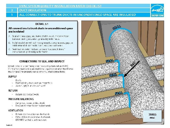
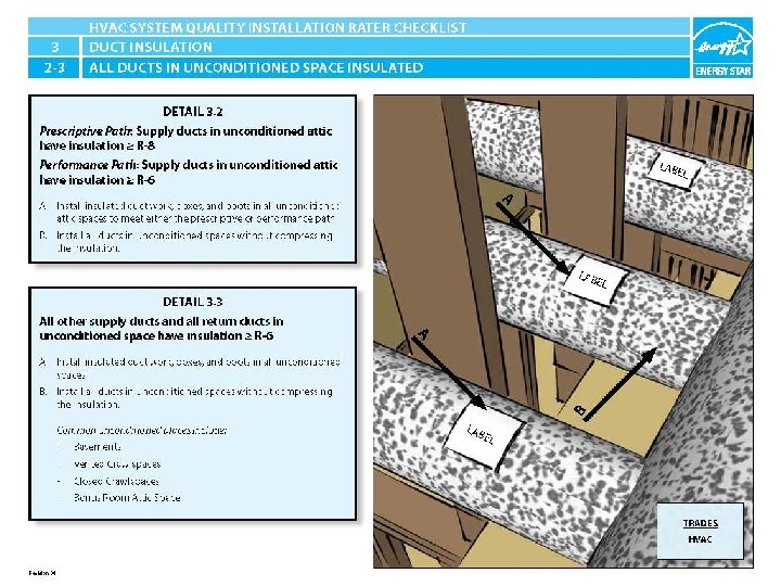
ENERGY STAR® QUALIFIED HOMES HVAC SYSTEM QUALITY INSTALLATION RATER CHECKLIST SECTION 3. DUCT INSULATION : Applies to All Heating, Cooling, Supply Ventilation, and Pressure Balancing Ducts 14 3. 1 All connections to trunk ducts in unconditioned space are insulated. 3. 2 Prescriptive Path: Supply ducts in unconditioned attic have insulation > R-8. Performance Path: Supply ducts in unconditioned attic have insulation > R-6. 3. 3 All other supply ducts and all return ducts in unconditioned space have insulation > R-6.
ENERGY STAR® QUALIFIED HOMES HVAC SYSTEM QUALITY INSTALLATION RATER CHECKLIST SECTION 3. DUCT INSULATION 3. 1 All connections to trunk ducts in unconditioned space are insulated.
3. 1 All connections to trunk ducts in unconditioned space are insulated. CJ LD A Trunk to duct connections are only mechanically fastened and not sealed. Trunk to duct connections are properly insulated and have been sealed with mastic. HVAC System Quality Installation Rater Checklist
3. 1 All connections to trunk ducts in unconditioned space are insulated. CJ LD A Ductwork is uninsulated and not sealed at seams. Seams are being properly sealed with mastic and mesh tape. HVAC System Quality Installation Rater Checklist
3. 1 All connections to trunk ducts in unconditioned space are insulated. CJ LD B Boot is uninsulated. Duct insulation is installed over boot. HVAC System Quality Installation Rater Checklist
3. 1 All connections to trunk ducts in unconditioned space are insulated. CJ LD C Insulation does not cover boot and is not sealed. Boot has been covered with insulation and sealed with mastic. HVAC System Quality Installation Rater Checklist
ENERGY STAR® QUALIFIED HOMES HVAC SYSTEM QUALITY INSTALLATION RATER CHECKLIST SECTION 3. DUCT INSULATION 3. 2 Prescriptive Path: Supply ducts in unconditioned attic have insulation ≥ R-8. Performance Path: Supply ducts in unconditioned attic have insulation ≥ R-6.
3. 2 -3 Prescriptive Path: Supply ducts in unconditioned attic have insulation ≥ R-8. Performance Path: Supply ducts in unconditioned attic have insulation ≥ R-6. CJ LD A Duct is located in unconditioned space and is not insulated. Duct is located in unconditioned space and is properly insulated. HVAC System Quality Installation Rater Checklist
3. 2 -3 Prescriptive Path: Supply ducts in unconditioned attic have insulation ≥ R-8. Performance Path: Supply ducts in unconditioned attic have insulation ≥ R-6. CJ LD B Duct is insulated but strapping is compressing the insulation therefore reducing the Rvalue. Ducts are properly insulated and supported without compressing the insulation. HVAC System Quality Installation Rater Checklist
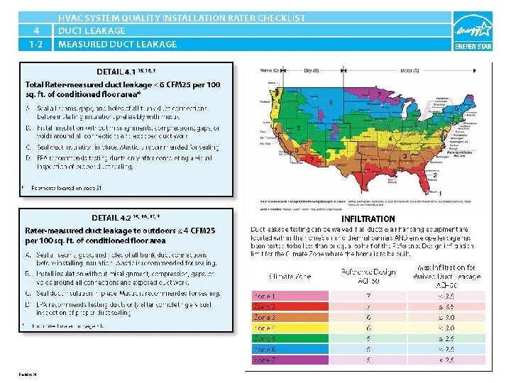
ENERGY STAR® QUALIFIED HOMES HVAC SYSTEM QUALITY INSTALLATION RATER CHECKLIST SECTION 4. DUCT LEAKAGE 4. 1 Total Rater-measured duct leakage < 6 CFM 25 per 100 sq. ft. of conditioned floor area 15, 16 4. 2 Rater -measured duct leakage to outdoors < 4 CFM 25 per 100 sq. ft. of conditioned floor area. 15, 16, 17 4. 3 Duct boots sealed to floor, wall, or ceiling using caulk, foam, mastic tape, or mastic paste.
ENERGY STAR® QUALIFIED HOMES HVAC SYSTEM QUALITY INSTALLATION RATER CHECKLIST SECTION 4. DUCT LEAKAGE 4. 1 Total Rater-measured duct leakage ≤ 6 CFM 25 per 100 sq. ft. of conditioned floor area 15, 16 4. 2 Rater -measured duct leakage to outdoors ≤ 4 CFM 25 per 100 sq. ft. of conditioned floor area. 15, 16, 17
4. 1 -2 Total Rater-measured duct leakage ≤ 6 CFM 25 per 100 sq. ft. of conditioned floor area 15, 16 Rater -measured duct leakage to outdoors ≤ 4 CFM 25 per 100 sq. ft. of conditioned floor area. 15, 16, 17 CJ LD A Connection in place but not sealed. Mechanically fastened and sealed. HVAC System Quality Installation Rater Checklist
4. 1 -2 Total Rater-measured duct leakage ≤ 6 CFM 25 per 100 sq. ft. of conditioned floor area 15, 16 Rater -measured duct leakage to outdoors ≤ 4 CFM 25 per 100 sq. ft. of conditioned floor area. 15, 16, 17 CJ LD B Insulation does not cover boot and is not sealed. Duct insulation is installed over boot. HVAC System Quality Installation Rater Checklist
4. 1 -2 Total Rater-measured duct leakage ≤ 6 CFM 25 per 100 sq. ft. of conditioned floor area 15, 16 Rater -measured duct leakage to outdoors ≤ 4 CFM 25 per 100 sq. ft. of conditioned floor area. 15, 16, 17 CJ LD C Insulation does not cover boot and is not sealed. Boot has been covered with insulation and sealed with mastic. HVAC System Quality Installation Rater Checklist
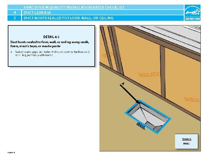
ENERGY STAR® QUALIFIED HOMES HVAC SYSTEM QUALITY INSTALLATION RATER CHECKLIST SECTION 4. DUCT LEAKAGE 4. 3 Duct boots sealed to floor, wall, or ceiling using caulk, foam, mastic tape, or mastic paste.
4. 3 Duct boots sealed to floor, wall, or ceiling using caulk, foam, mastic tape, or mastic paste. CJ LD A Boot to floor connection not sealed. Boot to floor connection sealed. HVAC System Quality Installation Rater Checklist
4. 3 Duct boots sealed to floor, wall, or ceiling using caulk, foam, mastic tape, or mastic paste. CJ LD A Boot to drywall connection not sealed. Boot to drywall connection sealed.
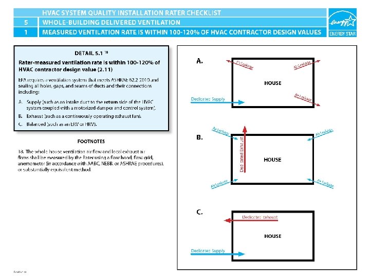
ENERGY STAR® QUALIFIED HOMES HVAC SYSTEM QUALITY INSTALLATION RATER CHECKLIST SECTION 5. WHOLE-BUILDING DELIVERED VENTILATION 5. 1 Rater-measured ventilation rate is within 100 -120% of HVAC contractor design value (2. 11). 18
5. 1 Rater-measured ventilation rate is within 100120% of HVAC contractor design value (2. 11). 18 CJ LD A Ventilation tied into the return without a mechanical damper. Ventilation tied into the return with a mechanical damper.
5. 1 Rater-measured ventilation rate is within 100120% of HVAC contractor design value (2. 11). 18 CJ LD B Exhaust fan installed but in wrong direction causing excessive bend and duct is uninsulated. In line exhaust ventilation installed. HVAC System Quality Installation Rater Checklist
5. 1 Rater-measured ventilation rate is within 100120% of HVAC contractor design value (2. 11). 18 CJ CJ C Properly installed ERV/HRV. HVAC System Quality Installation Rater Checklist
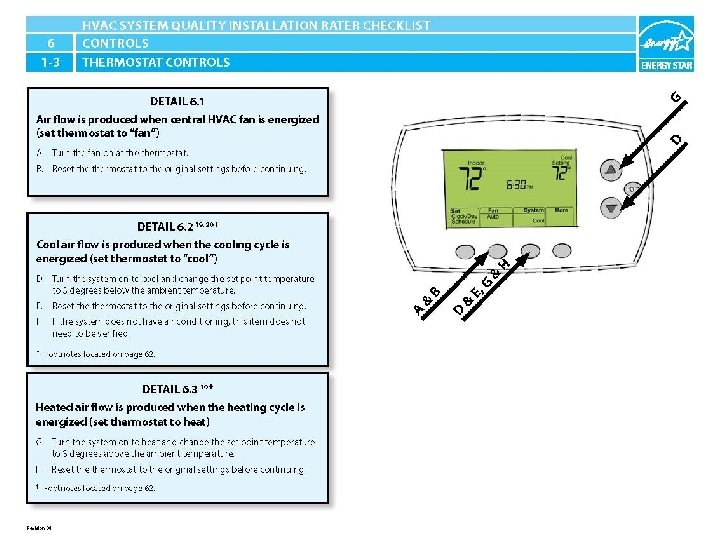
ENERGY STAR® QUALIFIED HOMES HVAC SYSTEM QUALITY INSTALLATION RATER CHECKLIST SECTION 6. CONTROLS 6. 1 Air flow is produced when central HVAC fan is energized (set thermostat to “fan”). 6. 2 Cool air flow is produced when the cooling cycle is energized (set thermostat to “cool”). 19, 20 6. 3 Heated air flow is produced when the heating cycle is energized (set thermostat to “heat”). 19 6. 4 Continuously-operating ventilation & exhaust fans include readily accessible override controls.
ENERGY STAR® QUALIFIED HOMES HVAC SYSTEM QUALITY INSTALLATION RATER CHECKLIST SECTION 6. VENTILATION CONTROLS 6. 5 Function of ventilation controls is obvious (e. g. , bathroom exhaust fan) or, if not, controls have been labeled.
ENERGY STAR® QUALIFIED HOMES HVAC SYSTEM QUALITY INSTALLATION RATER CHECKLIST SECTION 6. VENTILATION CONTROLS 6. 1 Air flow is produced when central HVAC fan is energized (set thermostat to “fan”). 6. 2 Cool air flow is produced when the cooling cycle is energized (set thermostat to “cool”). 19, 20 6. 3 Heated air flow is produced when the heating cycle is energized (set thermostat to “heat”). 19
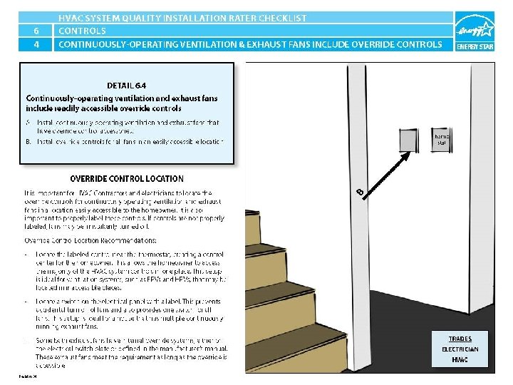
ENERGY STAR® QUALIFIED HOMES HVAC SYSTEM QUALITY INSTALLATION RATER CHECKLIST SECTION 6. VENTILATION CONTROLS 6. 4 Continuously-operating ventilation & exhaust fans include readily accessible override controls.
6. 4 Continuously-operating ventilation & exhaust fans include readily accessible override controls. CJ LD A BAD PIC OF EQUIPMENT INSTALLED WITHOUT OVERRIDE CONTROL OPTIONS? OR PIC OF EQUIPMENT INSTALLED WITHOUT IT GOOD PIC OF EQUIPMENT INSTALLED WITH OVERRIDE CONTROL OPTIONS
6. 4 Continuously-operating ventilation & exhaust fans include readily accessible override controls. CJ LD B BAD PIC OF BAD LOCATION FOR OVERRIDE EQUIP. Override control switches centrally located near thermostat for ease of access.
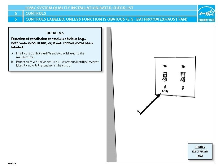
ENERGY STAR® QUALIFIED HOMES HVAC SYSTEM QUALITY INSTALLATION RATER CHECKLIST SECTION 6. VENTILATION CONTROLS 6. 5 Function of ventilation controls is obvious (e. g. , bathroom exhaust fan) or, if not, controls have been labeled.
6. 5 Function of ventilation controls is obvious (e. g. , bathroom exhaust fan) or, if not, controls have been labeled. CJ LD A Ventilation is not labeled. Manufacturer labeled ventilation switch.
6. 5 Function of ventilation controls is obvious (e. g. , bathroom exhaust fan) or, if not, controls have been labeled. CJ LD A Controls are not labeled. Manufacturer labeled controls.
6. 5 Function of ventilation controls is obvious (e. g. , bathroom exhaust fan) or, if not, controls have been labeled. CJ LD B Ventilation is not labeled. Installer permanently labeled ventilation switch.
ENERGY STAR® QUALIFIED HOMES HVAC SYSTEM QUALITY INSTALLATION RATER CHECKLIST SECTION 7. AIR INLETS & VENTILATION SOURCE 7. 1 All ventilation air inlets located ≥ 10 ft. of stretchedstring distance from known contamination sources such as stack, vent, exhaust hood, or vehicle exhaust. Exception: ventilation air inlets in the wall ≥ 3 ft. from dryer exhausts and contamination sources exiting through the roof. 21 7. 2 Ventilation air inlets ≥ 2 ft. above grade or roof deck in Climate Zones 1 -3 or ≥ 4 ft. above grade or roof deck in Climate Zones 4 -8 and not obstructed by snow, plantings, condensing units or other material at time of inspection. 22
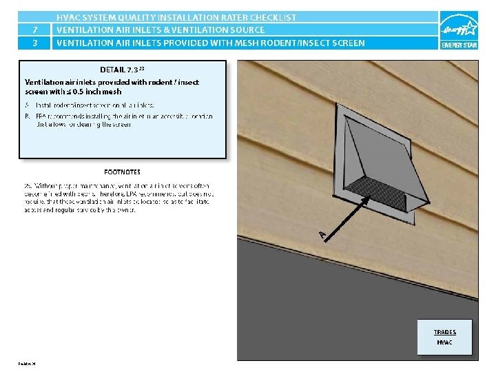
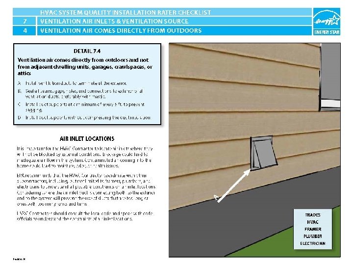
ENERGY STAR® QUALIFIED HOMES HVAC SYSTEM QUALITY INSTALLATION RATER CHECKLIST SECTION 7. AIR INLETS & VENTILATION SOURCE 7. 3 Ventilation air inlets provided with rodent / insect screen with ≤ 0. 5 inch mesh. 23 7. 4 Ventilation air comes directly from outdoors and not from adjacent dwelling units, garages, crawlspaces, or attics.
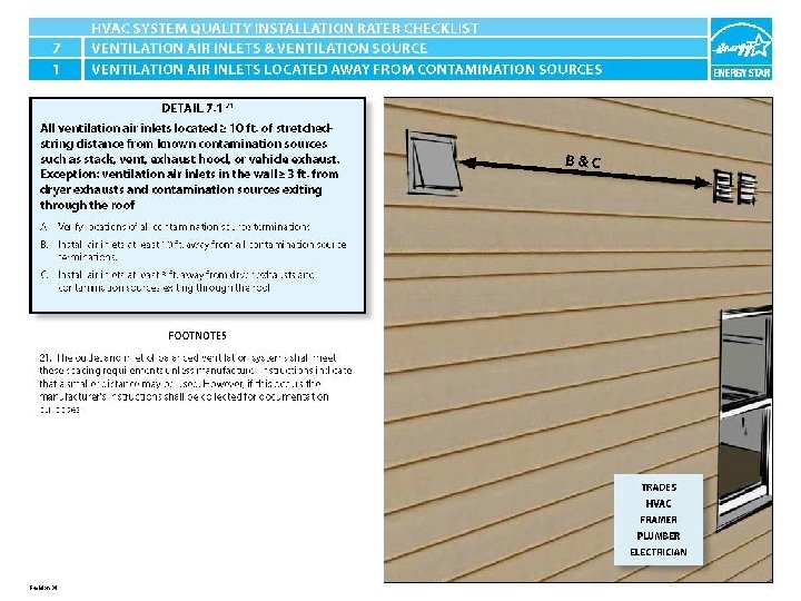
ENERGY STAR® QUALIFIED HOMES HVAC SYSTEM QUALITY INSTALLATION RATER CHECKLIST SECTION 7. AIR INLETS & VENTILATION SOURCE 7. 1 All ventilation air inlets located ≥ 10 ft. of stretchedstring distance from known contamination sources such as stack, vent, exhaust hood, or vehicle exhaust. Exception: ventilation air inlets in the wall ≥ 3 ft. from dryer exhausts and contamination sources exiting through the roof. 21
7. 1 All ventilation air inlets located ≥ 10 ft. of stretched-string distance from known contamination sources such as stack, vent, exhaust hood, or vehicle exhaust. Exception: ventilation air inlets in the wall ≥ 3 ft. from dryer exhausts and contamination sources exiting through the roof. 21 CJ LD B Ventilation air inlet is too close to exhaust outlet. Ventilation inlet is greater than 10 ft. from known contamination source. HVAC System Quality Installation Rater Checklist
7. 1 All ventilation air inlets located ≥ 10 ft. of stretched-string distance from known contamination sources such as stack, vent, exhaust hood, or vehicle exhaust. Exception: ventilation air inlets in the wall ≥ 3 ft. from dryer exhausts and contamination sources exiting through the roof. 21 CJ LD B Ventilation air inlet is too close to exhaust outlet. Ventilation inlet is greater than 10 ft. from known contamination source. HVAC System Quality Installation Rater Checklist
7. 1 All ventilation air inlets located ≥ 10 ft. of stretched-string distance from known contamination sources such as stack, vent, exhaust hood, or vehicle exhaust. Exception: ventilation air inlets in the wall ≥ 3 ft. from dryer exhausts and contamination sources exiting through the roof. 21 CJ LD B Ventilation inlet is too close to exhaust outlets and does not extend at least 2 ft. above the roof deck. Ventilation inlet is not near any exhaust outlets/contamination sources and is at least 2 ft. above the roof deck. HVAC System Quality Installation Rater Checklist
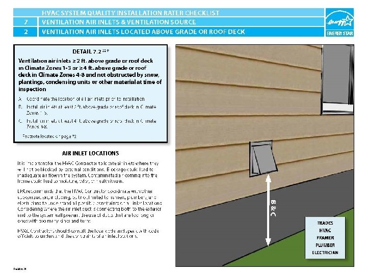
ENERGY STAR® QUALIFIED HOMES HVAC SYSTEM QUALITY INSTALLATION RATER CHECKLIST SECTION 7. AIR INLETS & VENTILATION SOURCE 7. 2 Ventilation air inlets ≥ 2 ft. above grade or roof deck in Climate Zones 1 -3 or ≥ 4 ft. above grade or roof deck in Climate Zones 4 -8 and not obstructed by snow, plantings, condensing units or other material at time of inspection. 22
7. 2 Ventilation air inlets ≥ 2 ft. above grade or roof deck in Climate Zones 1 -3 or ≥ 4 ft. above grade or roof deck in Climate Zones 4 -8 and not obstructed by snow, plantings, condensing units or other material at time of inspection. 22 CJ LD B Ventilation inlet does not terminate high enough above the roof deck. Ventilation inlet is not near any exhaust outlets/contamination sources and is at least 2 ft. above the roof deck. HVAC System Quality Installation Rater Checklist
7. 2 Ventilation air inlets ≥ 2 ft. above grade or roof deck in Climate Zones 1 -3 or ≥ 4 ft. above grade or roof deck in Climate Zones 4 -8 and not obstructed by snow, plantings, condensing units or other material at time of inspection. 22 CJ LD C Ventilation inlet is too close to the ground and is being blocked by the grass. Ventilation inlet is appropriately located above grade. HVAC System Quality Installation Rater Checklist
ENERGY STAR® QUALIFIED HOMES HVAC SYSTEM QUALITY INSTALLATION RATER CHECKLIST SECTION 7. AIR INLETS & VENTILATION SOURCE 7. 3 Ventilation air inlets provided with rodent / insect screen with ≤ 0. 5 inch mesh. 23
7. 3 Ventilation air inlets provided with rodent / insect screen with ≤ 0. 5 inch mesh. 23 CJ LD A Mesh screen is spaced wider than 0. 5" allowing insects to enter. Mesh screen is correctly installed and gaps are less than 0. 5". HVAC System Quality Installation Rater Checklist
7. 3 Ventilation air inlets provided with rodent / insect screen with ≤ 0. 5 inch mesh. 23 CJ LD A Mesh screen is spaced wider than 0. 5" allowing insects to enter. Mesh screen is correctly installed and gaps are smaller less than 0. 5". HVAC System Quality Installation Rater Checklist
7. 3 Ventilation air inlets provided with rodent / insect screen with ≤ 0. 5 inch mesh. 23 CJ LD B Air inlet is not convenient for cleaning and located next to exhaust outlets. Air inlet is located in a convenient place for homeowner to clean. HVAC System Quality Installation Rater Checklist
ENERGY STAR® QUALIFIED HOMES HVAC SYSTEM QUALITY INSTALLATION RATER CHECKLIST SECTION 7. AIR INLETS & VENTILATION SOURCE 7. 4 Ventilation air comes directly from outdoors and not from adjacent dwelling units, garages, crawlspaces, or attics.
7. 4 Ventilation air comes directly from outdoors and not from adjacent dwelling units, garages, crawlspaces, or attics. CJ LD A Exhaust terminates inside of soffit and was just covered. Exhaust terminates to the outside away from air inlets. HVAC System Quality Installation Rater Checklist
7. 4 Ventilation air comes directly from outdoors and not from adjacent dwelling units, garages, crawlspaces, or attics. CJ LD B Exhaust duct only mechanically fastened and not sealed. Kitchen exhaust properly installed and sealed with mastic. HVAC System Quality Installation Rater Checklist
7. 4 Ventilation air comes directly from outdoors and not from adjacent dwelling units, garages, crawlspaces, or attics. LD CJ C/D Ventilation duct is compressed because supporting strap is too small. Ventilation air comes directly from outdoors and not from adjacent dwelling units, garages, crawlspaces, or attics. HVAC System Quality Installation Rater Checklist
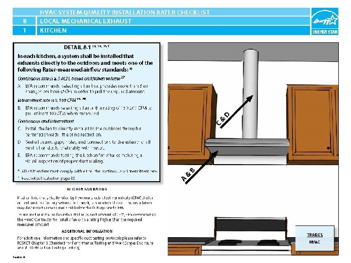
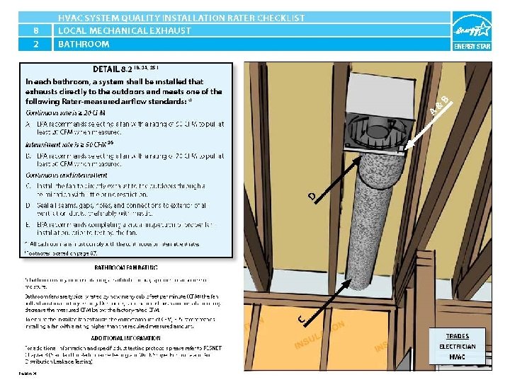
ENERGY STAR® QUALIFIED HOMES HVAC SYSTEM QUALITY INSTALLATION RATER CHECKLIST SECTION 8. LOCAL MECHANICAL EXHAUST In each kitchen and bathroom, a system shall be installed that exhausts directly to the outdoors and meets one of the following Rater measured airflow standards: 18, 24, 25 Location Continuous Rate Intermittent Rate 8. 1 Kitchen ≥ 5 ACH, based on kitchen volume 27 ≥ 100 CFM 28 8. 2 Bathroom ≥ 20 CFM ≥ 50 CFM 26
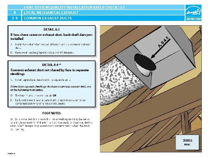
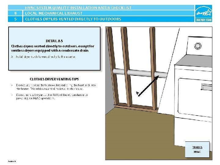
ENERGY STAR® QUALIFIED HOMES HVAC SYSTEM QUALITY INSTALLATION RATER CHECKLIST SECTION 8. LOCAL MECHANICAL EXHAUST 8. 3 If fans share common exhaust duct, back-draft dampers installed. 8. 4 Common exhaust duct not shared by fans in separate dwellings. 29 8. 5 Clothes dryers vented directly to outdoors, except for ventless dryers equipped with a condensate drain.
ENERGY STAR® QUALIFIED HOMES HVAC SYSTEM QUALITY INSTALLATION RATER CHECKLIST SECTION 8. LOCAL MECHANICAL EXHAUST In each kitchen and bathroom, a system shall be installed that exhausts directly to the outdoors and meets one of the following Rater measured airflow standards: 18, 24, 25 8. 1 Kitchen Continuous: ≥ 5 ACH, based on kitchen volume 27 Intermittent Rate 26 : ≥ 100 CFM 28
8. 1 In each kitchen and bathroom, a system shall be installed that exhausts directly to the outdoors and meets one of the following Rater measured airflow standards: 18, 24, 25 ≥ 5 ACH, based on kitchen volume 27 OR ≥ 100 CFM 28 LD CJ A/B CFM rating may not meet the performance specification once installed. Fan CFM rating is higher than the requirement increasing the likelihood that it will meet the performance level once installed. HVAC System Quality Installation Rater Checklist
8. 1 In each kitchen and bathroom, a system shall be installed that exhausts directly to the outdoors and meets one of the following Rater measured airflow standards: 18, 24, 25 ≥ 5 ACH, based on kitchen volume 27 OR ≥ 100 CFM 28 CJ LD C Recirculating fan installed that does not exhaust to outside. Exhaust fan has terminates to the outside. HVAC System Quality Installation Rater Checklist
8. 1 In each kitchen and bathroom, a system shall be installed that exhausts directly to the outdoors and meets one of the following Rater measured airflow standards: 18, 24, 25 ≥ 5 ACH, based on kitchen volume 27 OR ≥ 100 CFM 28 CJ LD D Exhaust ductwork and penetration to the exterior have not been sealed. Exhaust ductwork and penetration to the exterior have been sealed with mastic.
ENERGY STAR® QUALIFIED HOMES HVAC SYSTEM QUALITY INSTALLATION RATER CHECKLIST SECTION 8. LOCAL MECHANICAL EXHAUST In each kitchen and bathroom, a system shall be installed that exhausts directly to the outdoors and meets one of the following Rater measured airflow standards: 18, 24, 25 8. 2 Bathroom Continuous: ≥ 20 CFM Intermittent Rate 26 : ≥ 50 CFM
8. 2 In each kitchen and bathroom, a system shall be installed that exhausts directly to the outdoors and meets one of the following Rater measured airflow standards: 18, 24, 25 ≥ 20 CFM OR ≥ 50 CFM LD CJ A/B CFM rating may not meet the performance specification once installed. Fan CFM rating is higher than the requirement increasing the likelihood that it will meet the performance level once installed. HVAC System Quality Installation Rater Checklist
8. 2 In each kitchen and bathroom, a system shall be installed that exhausts directly to the outdoors and meets one of the following Rater measured airflow standards: 18, 24, 25 ≥ 20 CFM OR ≥ 50 CFM CJ LD C Two exhaust terminations, joined in a roughly cut hole restrictive hole and not air sealed. Exhaust has been properly installed, sealed, and terminates to outdoors. HVAC System Quality Installation Rater Checklist
8. 2 In each kitchen and bathroom, a system shall be installed that exhausts directly to the outdoors and meets one of the following Rater measured airflow standards: 18, 24, 25 ≥ 20 CFM OR ≥ 50 CFM CJ LD D Exhaust duct only mechanically fastened and not sealed. Exhaust duct has been mechanically fastened and sealed with mastic. HVAC System Quality Installation Rater Checklist
ENERGY STAR® QUALIFIED HOMES HVAC SYSTEM QUALITY INSTALLATION RATER CHECKLIST SECTION 8. LOCAL MECHANICAL EXHAUST 8. 3 If fans share common exhaust duct, back-draft dampers installed. 8. 4 Common exhaust duct not shared by fans in separate dwellings. 29
8. 3 -4 If fans share common exhaust duct, back-draft dampers installed AND Common exhaust duct not shared by fans in separate dwellings. 29 CJ LD A Fan shares exhaust and does not have a back-draft damper installed. Fan shares exhaust and has a back-draft damper installed. HVAC System Quality Installation Rater Checklist
8. 3 -4 If fans share common exhaust duct, back-draft dampers installed AND Common exhaust duct not shared by fans in separate dwellings. 29 CJ LD B Back-draft damper still has a piece of tape that prevented it from rattling during shipping. Packing tape has been removed and damper will be able to function properly once fan is installed. HVAC System Quality Installation Rater Checklist
8. 3 -4 If fans share common exhaust duct, back-draft dampers installed AND Common exhaust duct not shared by fans in separate dwellings. 29 CJ LD C Fans from separate dwellings exhausted together without back-draft dampers and not sealed. Separate dwellings with their own separate exhaust terminations.
ENERGY STAR® QUALIFIED HOMES HVAC SYSTEM QUALITY INSTALLATION RATER CHECKLIST SECTION 8. LOCAL MECHANICAL EXHAUST 8. 5 Clothes dryers vented directly to outdoors, except for ventless dryers equipped with a condensate drain.
8. 5 Clothes dryers vented directly to outdoors, except for ventless dryers equipped with a condensate drain. CJ LD A Dryer vent is run vertical with a 90 degree bend and does not vent to the outside. Dryer vents directly to the outdoors. HVAC System Quality Installation Rater Checklist
8. 5 Clothes dryers vented directly to outdoors, except for ventless dryers equipped with a condensate drain. CJ LD A Dryer exhaust line terminates in the crawlspace. Dryer vents directly to the outdoors. HVAC System Quality Installation Rater Checklist
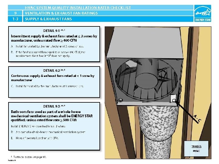
ENERGY STAR® QUALIFIED HOMES HVAC SYSTEM QUALITY INSTALLATION RATER CHECKLIST SECTION 9. VENTILATION & EXHAUST FAN RATINGS (EXEMPTIONS FOR HVAC AND REMOTE-MOUNTED FANS) 30 9. 1 Intermittent supply & exhaust fans rated at ≤ 3 sones by mfr. , unless rated flow ≥ 400 CFM 9. 2 Continuous supply & exhaust fans rated at ≤ 1 sone by manufacturer. 9. 3 Bathroom fans used as part of a whole-house mechanical ventilation system shall be ENERGY STAR qualified; unless rated flow rate ≥ 500 CFM.
9. 1 -3 Intermittent supply & exhaust fans rated at ≤ 3 sones by mfr. , unless rated flow ≥ 400 CFM LD CJ INTERMITTENT FAN SONE RATING — Verify fans are installed with less than 3 sones by manufacturer. HVAC System Quality Installation Rater Checklist
9. 1 -3 Continuous supply & exhaust fans rated at ≤ 1 sone by manufacturer. CJ LD C Sone rating is greater than 1 on a continuous exhaust fan. Sone rating is less than or equal to 1 on a continuous exhaust fan. HVAC System Quality Installation Rater Checklist
9. 1 -3 Bathroom fans used as part of a whole-house mechanical ventilation system shall be ENERGY STAR qualified; unless rated flow rate ≥ 500 CFM. LD CJ D/E The fan does not have an ENERGY STAR label. The fan has an ENERGY STAR label. HVAC System Quality Installation Rater Checklist
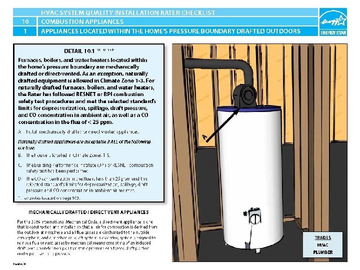
ENERGY STAR® QUALIFIED HOMES HVAC SYSTEM QUALITY INSTALLATION RATER CHECKLIST SECTION 10. COMBUSTION APPLIANCES 10. 1 Furnaces, boilers, and water heaters located within the home’s pressure boundary are mechanically drafted or direct-vented. As an exception, naturally drafted equipment is allowed in Climate Zone 1 -3. For naturally drafted furnaces, boilers, and water heaters, the Rater has followed RESNET or BPI combustion safety test procedures and met the selected standard’s limits for depressurization, spillage, draft pressure, and CO concentration in ambient air, as well as a CO concentration in the flue of ≤ 25 ppm. 31, 32, 33
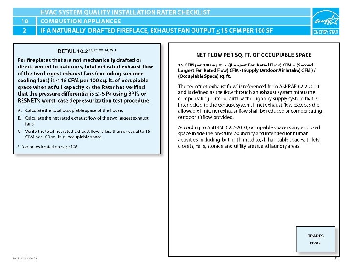
ENERGY STAR® QUALIFIED HOMES HVAC SYSTEM QUALITY INSTALLATION RATER CHECKLIST SECTION 10. COMBUSTION APPLIANCES 10. 2 For fireplaces that are not mechanically drafted or direct-vented to outdoors, total net rated exhaust flow of the two largest exhaust fans (excluding summer cooling fans) is < 15 CFM per 100 sq. ft. of occupiable space when at full capacity or the Rater has verified that the pressure differential is ≤ -5 Pa using BPI’s or RESNET’s worst-case depressurization test procedure. 24, 32, 33, 34, 35
ENERGY STAR® QUALIFIED HOMES HVAC SYSTEM QUALITY INSTALLATION RATER CHECKLIST SECTION 10. COMBUSTION APPLIANCES 10. 3 If unvented combustion appliances other than cooking ranges are located inside the home’s pressure boundary, the Rater has operated the appliance for at least 10 minutes and verified that the ambient CO level does not exceed 35 ppm. 36
ENERGY STAR® QUALIFIED HOMES HVAC SYSTEM QUALITY INSTALLATION RATER CHECKLIST SECTION 10. COMBUSTION APPLIANCES 10. 1 Furnaces, boilers, and water heaters located within the home’s pressure boundary are mechanically drafted or direct-vented. As an exception, naturally drafted equipment is allowed in Climate Zone 1 -3. For naturally drafted furnaces, boilers, and water heaters, the Rater has followed RESNET or BPI combustion safety test procedures and met the selected standard’s limits for depressurization, spillage, draft pressure, and CO concentration in ambient air, as well as a CO concentration in the flue of ≤ 25 ppm. 31, 32, 33
10. 1 Furnaces, boilers, and water heaters located within the home’s pressure boundary are mechanically drafted or direct-vented to outdoors. If naturally drafted then combustion safety testing is required. 31, 32, 33 CJ LD A Atmospherically vented heater installed. Requires combustion safety testing. Direct vent appliance installed. HVAC System Quality Installation Rater Checklist
10. 1 Furnaces, boilers, and water heaters located within the home’s pressure boundary are mechanically drafted or direct-vented to outdoors. If naturally drafted then combustion safety testing is required. 31, 32, 33 CJ LD A Atmospherically vented water heater installed. Requires combustion safety testing. Power vented water heater installed. HVAC System Quality Installation Rater Checklist
ENERGY STAR® QUALIFIED HOMES HVAC SYSTEM QUALITY INSTALLATION RATER CHECKLIST SECTION 10. COMBUSTION APPLIANCES 10. 2 For fireplaces that are not mechanically drafted or direct-vented to outdoors, total net rated exhaust flow of the two largest exhaust fans (excluding summer cooling fans) is < 15 CFM per 100 sq. ft. of occupiable space when at full capacity or the Rater has verified that the pressure differential is ≤ -5 Pa using BPI’s or RESNET’s worst-case depressurization test procedure. 24, 32, 33, 34, 35
ENERGY STAR® QUALIFIED HOMES HVAC SYSTEM QUALITY INSTALLATION RATER CHECKLIST SECTION 10. COMBUSTION APPLIANCES 10. 3 If unvented combustion appliances other than cooking ranges are located inside the home’s pressure boundary, the Rater has operated the appliance for at least 10 minutes and verified that the ambient CO level does not exceed 35 ppm. 36
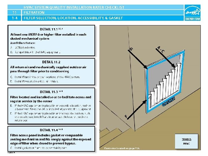
ENERGY STAR® QUALIFIED HOMES HVAC SYSTEM QUALITY INSTALLATION RATER CHECKLIST SECTION 11. FILTRATION 11. 1 At least one MERV 6 or higher filter installed in each ducted mechanical system. 37 11. 2 All return air and mechanically supplied outdoor air pass through filter prior to conditioning. 11. 3 Filter located and installed so as to facilitate access and regular service by the owner. 38 11. 4 Filter access panel includes gasket or comparable sealing mechanism and fits snugly against the exposed edge of filter when closed to prevent bypass. 39
11. 1 -4 At least one MERV 6 or higher filter installed in each ducted mechanical system. 37 CJ LD A The installed filter is not a MERV 6 filter. The installed filter is at least a MERV 6 filter. HVAC System Quality Installation Rater Checklist
11. 1 -4 At least one MERV 6 or higher filter installed in each ducted mechanical system. 37 CJ LD B BAD PIC OF INCORRECT FILTER FOR SYSTEM INSTALLED HVAC HOMEOWNER MANUAL SHOWING WHICH FILTER SHOULD BE INSTALLED OR PROPER FILTER INSTALLED HVAC System Quality Installation Rater Checklist
11. 1 -4 All return air and mechanically supplied outdoor air pass through filter prior to conditioning. CJ LD C There is no filter installed in the HVAC system. GOOD PIC OF MERV 6 OR HIGHER FILTER INSTALLED. HVAC System Quality Installation Rater Checklist
11. 1 -4 All return air and mechanically supplied outdoor air pass through filter prior to conditioning. CJ LD D There is no filter installed to filter the outdoor air. There is a filter installed to filter outdoor air. HVAC System Quality Installation Rater Checklist
11. 1 -4 Filter located and installed so as to facilitate access and regular service by the owner. 38 CJ LD E BAD PIC OF FILTER LOCATION GOOD PIC OF ACCESSIBLE FILTER LOCATION WITH MERV 6 INSTALLED HVAC System Quality Installation Rater Checklist
11. 1 -4 Filter located and installed so as to facilitate access and regular service by the owner. 38 CJ LD F The filter is installed in the crawlspace and is not easily accessible. GOOD PIC OF ACCESSIBLE FILTER LOCATION HVAC System Quality Installation Rater Checklist
11. 1 -4 Filter access panel includes gasket or comparable sealing mechanism and fits snugly against the exposed edge of filter when closed to prevent bypass. 39 CJ LD G No gasket at filter location. GOOD PIC OF GASKET AT FILTER LOCATION HVAC System Quality Installation Rater Checklist
ENERGY STAR® QUALIFIED HOMES HVAC SYSTEM QUALITY INSTALLATION RATER CHECKLIST EPA Disclaimer Any mention of trade names, commercial products and organizations in this document does not imply endorsement by the U. S. Environmental Protection Agency ("EPA") or the U. S. Government. The EPA and its collaborators make no warranties, whether expressed or implied, nor assume any legal liability or responsibility for the accuracy, completeness or usefulness of the contents of this publication, or any portion thereof, nor represent that its use would not infringe privately owned rights. Further, the EPA cannot be held liable for construction defects or deficiencies resulting from the proper or improper application of the content of this guidebook.