Energy Equation The expanded Bernoullis equation More general

Energy Equation • The expanded Bernoulli's equation • More general flow equation than Bernoulli’s • Includes energy loss or gained Recall of restrictions on the use of the Bernoulli’s eqn.
")
Motor Pump Valve • h. A = energy added by mechanical device ( pump) • h. R = energy removed ( motor / turbine ) • h. L = energy losses ( friction + minor losses)
 is proportional to the velocity head")
• The magnitude of friction, (head loss) is proportional to the velocity head • K = resistance coefficient found from Darcy-Weisbach equation Total Energy per unit weight (pts 1 and 2)

qua tion y. E So En erg But

Ø Ø Energy equation written in the direction of flow. The Algebraic signs are very critical From above: Ø Pump adds energy Ø Frictional losses remove energy Ø motor extracts energy

Example 1 Large reservoir 3. 5 m 4. 0 m 2 Find Q = 0. 03 m 3/s 10 cm

From point 1 point 2 Both points are exposed to the atmosphere Reservoir large, so very large surface area. No mechanical devices Hence or
 and minor (valves, elbows)")
These losses are frictional (pipe friction) and minor (valves, elbows)

Pump power Requirements Mechanical Efficiency
")
Fluid motors (turbines)

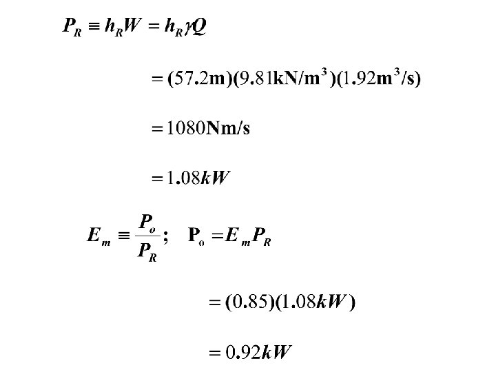
Example Given the following T = 100 c, Q = 115 l/min (1. 92 x 10 -3 m 3) PA = 700 k. Pa, PB = 125 k. Pa, h. L = 4. 0 m Calculate: PR, PO if Em = 0. 85 A 1. 8 m B

Solution Solve for

Applications of the Bernoulli's Equation 1 2 Note Streamlines move to the left and right Centre streamline, goes to the tip of the blunt body and stops. Velocity is zero - the fluid does not move at this point. Point (2) called stagnation point.

Pitot Tube 1 Open s
 between points 1 & S Now Hence")
Applying general Energy Equation (Bernoulli’s) between points 1 & S Now Hence

Static pressure = Static pressure head = velocity head Stagnation or total pressure Total pressure head Only the difference between the total pressure head and static pressure head gives velocity

Venturi-Meter Ø Venturi-meter - device for measuring discharge Ø Consists of a rapidly converging section which increases velocity of flow and hence reduces the pressure. Ø It then returns to the original dimensions of pipe by a gently diverging (diffuser) section. Ø Measuring pressure differences between two points the discharge can be calculated. Ø Energy loss in the venturi-meter is very small.

About 6 About 20

Apply Bernoulli's equation along the streamline from point 1 to 2 Using continuity equation find velocity u 2

Ø Substituting this into and rearranging the Bernoulli's equation

Hence theoretical discharge Actual discharge, taking into account losses due to friction

Express discharge in terms of the manometer readings Manometer Equation Simplify Hence actual discharge is

Expression for discharge does not include any terms for elevation or orientation (z 1 or z 2) of the venturi-meter. Hence the meter can be at any convenient angle to function. The smoother the contraction, the lesser the head loss Typically

The purpose of the diffuser in a Venturi-meter: • To assure gradual and steady deceleration after the throat. ØThis design is to ensure pressure rises again to a value near the original value before the venturimeter. • The angle of the diffuser is usually between 6 and 8 degrees. ØIf the angle is wider than this limit, the flow might separate from the walls resulting in increased friction, energy and pressure loss.

• If the angle is less than this limit, the meter becomes very long and pressure losses again become significant. The efficiency of the diffuser of increasing pressure back to the original is rarely greater than 80%.

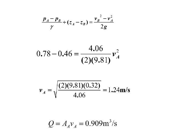
Example B 200 mm 0. 46 m A 300 mm Unknown “y” 1. 18 m Specific gravity = 1. 29

Known parameters Consider Point A and B

Manometer equation Now we need , so divide by

Using continuity Q=v. A

Flow through a Small Orifice 1 orifice h 2 Vena-contracta Datum • Consider flow from a tank through a hole (orifice) in the side close to the base. • General arrangement of streamlines as above

• Shape of holes edges is sharp - Contact between hole and the fluid minimized. Ø Hence frictional losses decreased. • Streamlines contract after the orifice to a minimum value when they become parallel. • At this point, the velocity and pressure become uniform across the jet. • Convergence is called vena-contracta. (‘Latin 'contracted vein').

• To calculate the flow, it is important to know the amount of contraction • Predict the velocity at the orifice using Bernoulli's equation. ØApply Bernoulli's equation to the streamline joining vpoint 1 on the surface of the reservoir to point 2 at the centre of the orifice.
 and the pressure atmospheric (p")
• Surface velocity negligible (u 1 = 0) and the pressure atmospheric (p 1 = 0). • At the orifice, jet is open to the air so pressure is atmospheric (p 2 = 0). • Datum line through the center of the orifice, Ø z 1 = h and z 2 =0 theoretical velocity
")
• Actual velocity Cv - coefficient of velocity (0. 97 - 0. 99) • Actual area of the jet is area of the vena-contracta not the area of the orifice. • Area at vena-contracta obtained by using the coefficient of contraction for the orifice Cc - coefficient of contraction

• Discharge through the orifice Cd - coefficient of discharge

Determination of Coefficient of Velocity Three methods used: Ø By measurement of coordinates (Trajectory method) Ø By momentum method Ø By pitot-tube
 H venacontracta x y y x Ø Measure")
By measurement of coordinates (Trajectory method) H venacontracta x y y x Ø Measure horizontal and vertical coordinates of the jet as it falls under gravity. Ø The jet contracts and forms the venacontracta at a distance of d/2 from plane of the orifice.

Let • u be the velocity at the venacontracta • x and y be the coordinates of a point on the jet after time t. • Applying the equation of motion

• Eliminating t But • So Knowing x and y, and the head H, Coefficient of velocity is obtained

• A circular orifice, 3. 5 cm diameter is made in the vertical wall of a tank. The jet falls vertically through 0. 5 m while moving horizontally through a distance of 1. 5 m. Calculate the coefficient of velocity if the head causing flow is 1. 2 m. If the discharge is 2. 80 * 10^-3 m^3, calculate

Time taken for fluid level to fall through h

In a small amount of time Volume Removed from tank The two are equal Solving for time

So Integrating from depth Time to drain a tank

Example What is the time taken to drain a tank from 3 m to 0. 5 m. Tank diameter, D = 1. 5 m; nozzle diameter = 50 mm. Take Cd = 0. 92 Solution:

Time for a Tank to Empty Tank empty

Notches and Weirs Depending on the shape Ø Rectangular Ø Triangular Ø Trapezoidal Depending on the form of the crest Ø Sharp crested Ø Broad crested Ø Others

SHARP CRESTED WEIR BROAD CRESTED WEIR

General Notch Equation b H h h

Discharge through the strip Integrating from the free surface To the weir crest Theoretical discharge Different for every differently shaped weir or notch

Rectangular Notch B H Rectangular Notch the width does not change with depth

Substitute into the general weir equation For actual discharge we introduce a coefficient of discharge constant for the given notch.

Example Find the discharge over a rectangular notch having width 2 m and a constant head of 300 mm. Assume coefficient of discharge for the notch as 0. 62 Soln. § Width of notch L=B = 2 m § Head over the notch, H = 0. 3 m § Coefficient of discharge Cd = 0. 62 ØDischarge

Example • A rectangular notch is discharging 300 l/s of water under a constant head of 200 mm. Find the width of the notch, if Cd = 0. 6

Calibration of a Rectangular Notch • A notch used for measuring discharge of fluid (e. g. water), must first be calibrated experimentally to find the constant K. • Two methods a. Plot a graph of Q against H 3/2

Find the gradient of the straight line and hence determine K

b. Using the relation Taking logs of both sides When H = 1, log. H = 0, The value of K can be found

Effect of error in the measurement of head on the discharge over a rectangular notch Differentiating Q, with respect to H, Therefore Or

Example The discharge over a rectangular notch 200 mm wide was found to be 11. 8 l/s. An error of 1 mm was made in the measurement of the head over the crest of the notch. Assuming the coefficient of discharge for the notch is 0. 623, calculate the percentage error in the discharge. Soln. Width of the notch B = 200 mm. Discharge over the notch Q = 11. 8*10 -3 m 3/s Error in the head d. H = 1 mm Coefficient of discharge Cd = 0. 623

Percentage error in discharge

Broad crested weirs. b >0. 66 H. H V b h

Applying the Bernoulli’s equation Differentiate w. r. t. variable h Hence

Velocity of Approach • Velocity of approach is assumed to be uniform over the whole weir

A 3 m long rectangular weir is discharging water under a constant head of 1 m. The channel approaching the weir is 5 m wide and 1. 2 m deep. Determine the Total head over the weir.

Special cases In practice for a rectagular weirs,
 L Contracted sides L Cipolleti")
L Broad Rectangular Weir (Suppressed) L Contracted sides L Cipolleti

Weir for irrigation project at Nobewam, Ghana
 after heavy rainfall. A weir at")
The weir at Coburg lake in Victoria (Australia) after heavy rainfall. A weir at the Thorp grist mill in Thorp, WA
")
'V' or Triangular Notch (Weirs)
, relationship between width and depth is dependent on the angle")
For "V" notch (weir), relationship between width and depth is dependent on the angle of the "V". b Angle of the V is and the width, b, at depth h

Actual discharge

Example • Water is flowing over a right angled triangular notch for which the coefficient of discharge is 0. 6. What will be the discharge if head is 50 cm. Example • Find the depth and top width of a triangular notch capable of discharging a maximum quantity of 700 lit/sec and such that the head shall be 8 cm when the discharge is 6 lit/sec. For a right angled notch, the constant for the notch, K = 1. 42.
- Slides: 73