EN 253203 Data Communication and Networking Layered Network


 developed a reference model for Open")

 • OSI model does not specify the exact services")


 • Take the raw transmission facilities, transform them into a")
 • Recognize the frame boundary – Special bit pattern (must")
 • Flow regulation – fast transmitter -> slow receiver (less")


 • Establish sessions between different machines – Log in to remote")
 • Concern with syntax and semantics of the information transmitted •")
 • Contains a variety of protocols • Example – Network virtual")


 • • Concept of a stack of independent")


 is defined to measures the relative")


 NRZ is")


 sent in")


, the original")


 232 is the serial line")
 standard")

 • The first WDM used two")
 • 16 or more channels (16")


 • CRC is the powerful")


- Slides: 66
EN 253203 Data Communication and Networking Layered Network Architecture Asst. Prof. Nararat Ruangchaijatupon Electrical Engineering Program Faculty of Engineering, KKU Office: EN 04325 A, Email: nararat@kku. ac. th
Pope Francis, left, and his cousin, Sister Ana Rosa Sivori visit the Supreme Buddhist Patriarch at Was Ratchabophit Sathit Maha Simaram Temple, Thursday, Nov. 21, 2019, in Bangkok, Thailand. (AP Photo/Gregorio Borgia) Source: http: //www. khaosodenglish. com/news/2019/11/21/pope-commits-church-to-work-with-thai-buddhists/ 2
OSI Model • International Organization for Standardization (ISO) developed a reference model for Open System Interconnection (OSI). • Because it deals with connecting open systems. • Systems that are open for connection with other systems. 3
OSI Reference Model Fig. 1 -16 4
OSI Reference Model (cont. ) • OSI model does not specify the exact services and protocols to be used in each layer. • It just tells what each layer should do. • However, ISO has produced international standards for all the layers but they are not the part of the reference model. 5
OSI Reference Model 6
OSI Reference Model closest to the end user. determining resource availability, and synchronizing communication. HTTP, SSH, IE, MSN, Skype translating between application and network formats and encrypts data to be sent across a network. MIME, HTML, CSS GIF. dialogues (connections) between computers, establishes, manages and terminates the connections. L 2 PT, PPTP, SSL, SQL. Transmission Control Protocol (TCP) and User Datagram Protocol (UDP), quality of service. IP address (IPv 4, IPv 6), Ipsec, IPX, Apple Talk, routing, subnet. Medium Access Control, Point-to-Point Protocol (PPP), ATM, Ethernet, IEEE 802. 11 the wireless LAN protocol. layout of pins, voltages, cable specifications, hubs, repeaters, 7 modulation, coding, medium. EIA/TIA-232, RJ 45, RJ 11.
Physical layer • Concern with transmitting raw bits over a communication channel • Make sure when one side sends bit “ 1”, the other side receives “ 1”, not “ 0” • How many volts, how many msec, how many pins in the connector and what each pin is used for • Mechanical, electrical, interfaces 8
Data Link Layer (1) • Take the raw transmission facilities, transform them into a line without transmission errors • Apparent to the network layer • Break input data into data frames • Transmit frames sequentially • Process the acknowledgement frames sent by the receiver 9
Data Link Layer (2) • Recognize the frame boundary – Special bit pattern (must not be incorrectly interpreted) • Since noise may destroy part of frame(s) or complete frame(s) – Damaged/lost frames -> retransmit – If the acknowledgement frame is lost -> Duplicated frames could be sent 10
Data Link Layer (3) • Flow regulation – fast transmitter -> slow receiver (less buffer space, less speed/bandwidth) • Error handling • If the line can transmit in both directions – Acknowledgement from B to A vs. Data from B to A -> piggybacking • Broadcast network – Multiple access control 11
Network Layer • Control the operation of subnets • How packets are routed from the source to the destination • Addressing • Static route vs. Dynamic route – The start of each conversion – Network load – Congestion control • Different protocols/different packet size 12
Transport Layer • Ultimate source and destination machines • Accept data from session layer – split it into smaller units • Host with several programs – tell which message belongs to which connection • If require high throughput – create multiple network connection • Multiplex several transport connections into the same connection to reduce cost • Flow of information -> flow control 13
Session Layer (1) • Establish sessions between different machines – Log in to remote timesharing systems – Transfer a file between 2 machines • Token management – If traffic can go one way at a time • Synchronization – Provide checkpoints if transmission fail during operation 14
Presentation Layer (1) • Concern with syntax and semantics of the information transmitted • Encoding data into a standard way • Different computers have different codes (ASCII, Unicode) 15
Application Layer (1) • Contains a variety of protocols • Example – Network virtual terminal – File transfer from different file systems with different naming conventions 16
Data Transmission in OSI Model Fig. 1 -17 • Actual data transmission is vertical • Each layer is programmed as though it were horizontal Source: Tanenbaum 1996, p. 34 17
TCP/IP Reference Model Fig. 1 -18 Source: Tanenbaum 1996, p. 36 • ARPANET -> The Internet • First defined: Carf and Kahn, 1974 • Later perspective: Leiner et al. , 1985 • Because sponsor was Depart. of Defense – Connections remain intact • Some machines/transmission lines were put off – Flexible architecture • Transfer files vs. real-time speech transmission 18
Host-to-Network Layer • Host has to connect to the network using some protocol • This protocol is not defined and varies from hostto-host, from network-tonetwork Source: https: //docs. microsoft. com/en-us/previous-versions/tn-archive/bb 726993(v=technet. 10)? redirectedfrom=MSDN 19
Internet Layer • Packet-switching network -> connectionless • Permits hosts to input packets into network • Have packets travel independently to destination (through different networks) • Packets may not arrive in-order • IP (Internet Protocol) specify packet format and protocol • Packet routing 20
Transport Layer • Allow peer entities on the source and the destination hosts to carry on conversation • 2 end-to-end protocols • TCP (Transport Control Protocol) – Connection-oriented, fragmentation, flow-control -> accurate delivery • UDP (User Datagram Protocol) – Connectionless, prompt delivery : speech/VDO – Do not want sequencing nor flow control 21
Application Layer • TCP/IP model does not have session/presentation layers -> little use • Application layers contains high-level protocols – TELNET -> virtual terminal – FTP -> file transfer – SMTP -> electronic mail – HTTP -> world wide web 22
OSI vs. TCP/IP models comparison (1) • • Concept of a stack of independent protocols OSI separates service, interface, protocol TCP/IP does not clearly distinguish OSI model was created before the protocol was invented • TCP/IP was created after the protocols (to describe the existing protocols) – Does not fit other protocols 23
Question & Discussion Assignment
25
2. Digital Transmission Fundamentals • Information can be represented in digital forms. For example, text, speech, audio, data, images and video. • Serial and Parallel transmission. • The transmission system uses pulses or sinusoids to transmit binary information over a physical transmission medium. • The capability of transmission system is affected by several factors including: ØAmount of energy put into transmitting each signal. ØThe distance that the signal has to transverse. ØThe amount of noise. ØThe bandwidth of the transmission medium
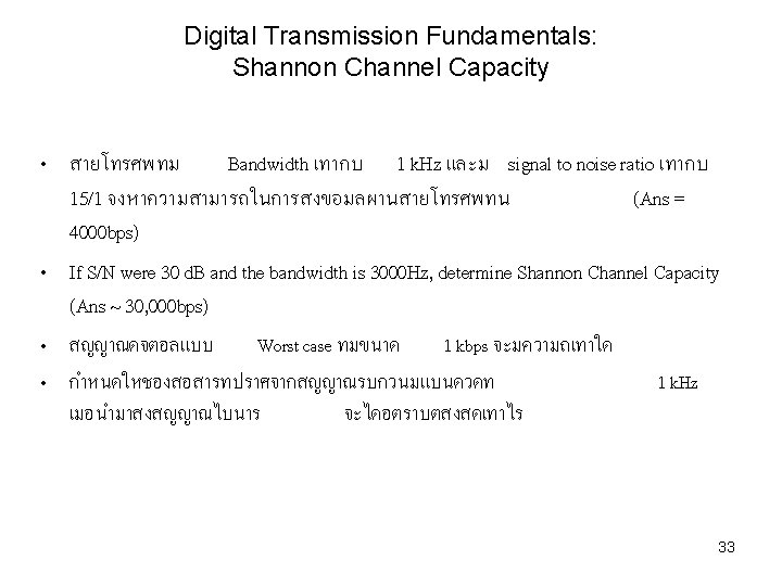
Digital Transmission Fundamentals: Channel Capacity • If channel has bandwidth W, then the narrowest pulse that can be transmitted over the channel has width T=1/2 W seconds. Thus the fastest rate at which pulses can be transmitted into the channel is given by the Nyquist rate: rmax = 2 W pulses/second. • The Nyquist rate is the maximum signaling rate that is achievable through an ideal low-pass channel with no intersymbol interference. • Question: what is bandwidth? Fourier? Why modulate signal? 28
Digital Transmission Fundamentals: Channel Capacity • • • Binary information can be transmitted by sending pulse with amplitude +A to send a 1 bit and –A to send a 0 bit. See fig. 3. 11. The system has a bit rate of 2 W pulse/sec x 1 bit/pulse = 2 W bps. Bit rate can be increased by sending pulses with more levels. For example, if pulse take on amplitudes from {-A, -A/3, A} to transmit {00, 01, 10, 11}, then each pulse conveys two bits and bit rate is 4 W bps. 29
Digital Transmission Fundamentals: Channel Capacity • If multilevel transmission is used, M=2 m amplitude levels, the bit rate is 2 Wm bits/second. • In the absence of noise, the bit rate can be increase without limit by increasing the number of signal levels M. What is Baud? (some call Baud rate, symbol rate). • • In digital communication systems, the physical layer gross bitrate, raw bitrate, data signaling rate, gross data transfer rate or uncoded transmission rate is the total number of physically transferred bits per second over a communication link, including useful data as well as protocol overhead. Symbol rate ≤ Gross bit rate = Symbol rate · m 30
Digital Transmission Fundamentals: cont’d • Signal-to-Noise Ratio (SNR) is defined to measures the relative amplitudes of the desired signal and the noise. 31
Digital Transmission Fundamentals: cont’d • Channel Capacity is the maximum rate at which bits can be transfer reliably. • In 1948, C. E. Shannon derived an expression for channel capacity. • The Shannon channel capacity is given by: where W is channel bandwidth. SNR is Signal-to-Noise Ratio • See, C. E. Shannon, “A Mathematical Theory of Communication”, The Bell System Technical Journal, Vol. 27, pp. 379 -423, 623 -656, July, October, 1948. 32
Digital Transmission Fundamentals: Channel Capacity • Baseband, defined by IEEE, is “the band of frequencies occupied by the (data signal) before it modulates a carrier (or subcarrier) frequency to form the transmitted line or radio signal. 34
Digital Transmission Fundamentals: Line Coding • • • Line coding is the method used for converting a binary information sequence into a digital signal in a digital communication system. The selection of line encoding involves several considerations such as bandwidth, the ease to recover signal, error detection, immunity to noise and interference. Bipolar = Bipolar-AMI 35
Digital Transmission Fundamentals: Line Coding 36
Digital Transmission Fundamentals: Line Coding • AMI = Alternate Mark Inversion 37
Digital Transmission Fundamentals: Line Coding 38
Digital Transmission Fundamentals: Line Coding 39
Digital Transmission Fundamentals: Line Coding • • • Nonreturn to Zero (NRZ) NRZ is the easiest way to transmit digital signals and make efficient use of bandwidth. NRZI is an example of differential coding. One benefit of this scheme is that it may be more reliable to detect transition in the presence of noise than to compare a value of a threshold. The main limitation of NRZ signals are the presence of a DC component and the lack of synchronization capability. For example, consider that with a long strings of 1 s or 0 s for NRZ-L or a long string of 0 s for NRZI, the output is a constant voltage over a long period of time. Any drift between the timing of transmitter and receiver will result in a loss of synchronization. NRZ codes are commonly used for digital magnetic recording. Limitations of NRZ make these code unattractive for signal transmission applications. 40
Digital Transmission Fundamentals: Line Coding • • Multilevel Binary Mutilevel binary address some of the deficiencies of the NRZ codes. These code use more than two signal levels. (Bipolar-AMI, pseudoternary) There will be no loss of synchronization if a long string of 1 s occurs. Because the 1 signals alternate in voltage from positive to negative, there is no net DC component. The bandwidth is considerably less than the bandwidth for NRZ. Simple error detection. A long string of 0 s still presents a problem. Multilevel binary signal requires approximately 3 d. B more signal power than a two-valued signal for the same probability of bit error. 41
Digital Transmission Fundamentals: Line Coding Biphase • • • Manchester and Differential Manchester are in common use to overcome the limitations of NRZ codes. In the Manchester code, there is a transition at the middle of each bit period. The mid-bit transition serves as a clocking mechanism and also as a data. All of the biphase technique require at least one transition per bit time and may have as many as two transitions. Thus, the maximum modulation rate is twice that for NRZ; This means the greater bandwidth required, but advantages are; Syncrhonization: Because of predictable transition during each bit time, the receiver can synchronize on that transition. The biphase are known as selfclocking code. No DC component: Error Detection: the absence of an expected transition can be used to detect errors. The bulk of the energy in biphase codes is between one-half and one times the bit rate. Thus the bandwidth is reasonably narrow and contains no DC component; however, it is wider than the bandwidth for the multilevel binary codes. Biphase codes are popular technique for data transmission. 42
Digital Transmission Fundamentals: Line Coding • • • Block & Linear Codes Line coding techniques can be classified to linear code and block codes. Biphase and AMI are linear codes. 4 B 3 T and 3 B 2 T are block code. 2 B 1 Q can be considered to either a block code, or a linear code. 2 B 1 Q, two binary bits are converted to on of four symbols. 4 B 3 T, 4 binary bits are converted to 3 ternary Bauds (3 level). 43 Line. Coding-Zarlink. pdf
Digital Transmission Fundamentals: Line Coding • 4 B/5 B is block coding. Each 4 -bit ‘nibbles’ has extra 5 th bit added. As a result, the 5 -bit patterns can always have two 1 s. This enable clock synchronization required for reliable data transfer. • The selection of the 5 -bit code is such that each code contains no more than one leading 0 and no more than two trailing 0 s. Therefore, when these 5 -bit codes are sent in sequence, no more than three consecutive 0 s are encountered. 44
Digital Transmission Fundamentals: Line Coding • 5 B/6 B Encoding is the process of encoding the scrambled 5 -bit data patterns into predetermined 6 -bit symbols. This creates a balanced data pattern, containing equal numbers of 0's and 1's, to provide guaranteed clock transitions synchronization for receiver circuitry. 5 B/6 B encoding also provides an added error-checking capability. • 8 B/6 T means send 8 data bits as six ternary (one of three voltage levels) signals. • 8 B/10 B, Each octet of data is examined and assigned a 10 bit code group. The data octet is split up into the 3 most significant bits and the 5 least significant bits. This is then represented as two decimal numbers with the least significant bits first e. g. for the octet 101 00110 we get the decimal 6. 5. 10 bits are used to create this code group and the naming convention follows the format /D 6. 5/. There also 12 special code groups which follow the naming convention /Kx. y/. 45
Digital Transmission Fundamentals: Line Coding • Data Rate – data elements (bits) sent in 1 sec – unit: bps (gross bitrate, raw bitrate, data signaling rate, gross data transfer rate or uncoded transmission rate) • Signal Rate – signal elements/pulses sent in 1 sec – unit: baud (symbol rate, modulation rate) • The physical layer net bitrate, information rate, useful bit rate, payload rate, net data transfer rate, coded transmission rate, effective data rate or wire speed (informal language) of a digital communication channel is the capacity excluding the physical layer protocol overhead. • Throughput denotes the achieved average useful bit rate in a computer network over a logical or physical communication link or through a network node, typically measured at a reference point above the datalink layer. The throughput often excludes data link layer protocol overhead. The throughput is affected by the traffic. • Goodput or data transfer rate refers to the achieved average net bit rate that is delivered to the application layer, exclusive of all protocol overhead, data packets retransmissions, etc. For example, in the case of file transfer, the goodput corresponds to the achieved file transfer rate. 46
Digital Transmission Fundamentals: Line Coding • 8 B/10 B encoding finds application are Fibre Channel, Gigabit Ethernet, Infini. Band, XAUI, and to modulate bytes of audio data on Digital Audio Tape • The overhead of the 64 b/66 b encoding is 3. 125%, which is considerably less than the 25% overhead of the previously used 8 b/10 b encoding scheme. • Technologies that use 64 b/66 b encoding 10 Gigabit Ethernet (most varieties), Fibre Channel 10 GFC and 16 GFC, 100 Gigabit Ethernet, 10 G-EPON, 10 Gbit/s Ethernet Passive Optical Network, Aurora from Xilinx, Infini. Band, Thunderbolt, Common Public Radio Interface • 128 b/130 b encoding, as used by PCIe 3. 0, and a very similar variant is the 128 b/132 b encoding used by USB 3. 1. 47
Digital Transmission Fundamentals: Line Coding Scrambling Techniques • The biphase techniques have widespread use in LAN, but they have not widely used in long-distance applications, because these techniques require a high signaling rate relative to the data rate. This sort of inefficiency is more costly in long-distance applications. • The idea behind the scrambling techniques is simple: sequences that would result in a constant voltage level on the line are replaced by filling sequences that will provide sufficient transitions for the receiver’s clock to maintain synchronization. • The design goals are: No DC component No long sequences of zero-level line signals No reduction in data rate Error-detection capability 48
Digital Transmission Fundamentals: Line Coding Scrambling Techniques • • Two techniques are commonly used in long-distance transmission services; Bipolar with 8 -zeros substitution (B 8 ZS) is commonly used in North America High-Density Bipolar of order 3 (HDB 3) code is commonly used in Europe and Japan. HDB 3 code replaces any instance of 4 consecutive 0 bits with one of the patterns "000 V" or "B 00 V" substitute 8 zeros substitute 4 zeros 49 substitute 4 zeros
Digital Transmission Fundamentals: Digital Modulation • • A band-pass channel is the channel that do not pass the lower frequencies and instead pass power in some frequency range from f 1 to f 2. W = f 1 - f 2 A modem is a device that carries out the function to produce a signal that contains the information sequence and that occupies frequencies in the range passed by the channel. 50
Digital Transmission Fundamentals: Digital Modulation • • In Quadrature Amplitude Modulation (QAM), the original information is split into two sequences that consist of the odd and even symbols, Ak and Bk. Ak is called the in-phase component and Bk is called the quadrature-phase component. 51
Digital Transmission Fundamentals: Signal Constellations 52
Digital Transmission Fundamentals: MODEM standards • Most telephone channel have bandwidth in the range f 1=500 Hz to f 2=2900 Hz. This implies W=2400 and hence signaling rate of 1/T = W = 2400 pulses/sec. • Trellis modulation systems are more complex in that they combine error-correcting coding with the modulation. • V. 34 bis standard can operate at rate of 2400, 2743, 2800, 3000, 3200 or 3429 pulses/sec. A range of bit rates are 2400, 4800, 9600, 14400, 19200, 28800, 31200 and 33600. 53
Digital Transmission Fundamentals: MODEM standards • Baud, Bit rate? FDM, TDM? Simplex, Duplex? • MODEM แบบ V. 29 มความเรวในการสงขอมล 9600 bps โดยใชการ Modulation แบบ 16 -QAM ทม 8 phase และ 2 ระดบสญญาณ จะม buad เทาไร (2400) 54
Digital Transmission Fundamentals: MODEM • The Recommended Standard (RS) 232 is the serial line interface provides connection between computer and communication devices. • Data Terminal Equipment (DTE), Data Communications Equipment (DCE); Data Circuit-terminating Equipment. 55
Digital Transmission Fundamentals: MODEM • RS 232 is an Electronics Industries Association (EIA) standard specifies interface between DTE and DCE. CCITT recommended a similar standard called V. 24. • The connectors have 9 or 25 pins D-type connectors, DB-9 and DB-25. 56
Digital Transmission Fundamentals: Optics 57
Digital Transmission Fundamentals: Optics Wave Division Multiplexing (WDM) • The first WDM used two channels, consisting of Shortwave and Longwave. The boundary between these two wavelengths was defined at 1100 nm. The first two WDM wavelengths were chosen and became the de-facto standard : 850 nm for SW, 1310 nm for LW 58
Digital Transmission Fundamentals: Optics Dense Wavelength-Division Multiplexing (DWDM) • 16 or more channels (16 and 40 channel systems are now common). 59
Digital Transmission Fundamentals: Error Detection • • • Parity checks and Cyclic Redundancy Check (CRC). Error detection requires redundancy Every error-detection technique will fail to detect some errors. Parity checks used in early transmission systems. There are two possible regimes for error detection: odd parity and even parity. For parity checking, count only 1’s in a bit sequence, ASCII code is 7 -bit code, an eighth bit is added as a parity bit. 0101001 has three 1 s, thus add 0 for the eighth bit if the parity is odd parity. 0101001 has three 1 s, thus add 1 for the eighth bit if the parity is even parity. 8 -N-1, 7 -E-1, 7 -O-1, 7 -E-2. Parity check is called Vertical Redundancy Checking (VRC). Its error detection capacity is weak. Detect only 1 -bit error. 60
Digital Transmission Fundamentals: Error Detection • • The other type of parity checking is called Longitudinal Redundancy Checking (LRC). Generally, LRC was used in addition to VRC to provide a more robust error detection capability, two-dimensional parity check. 61
Digital Transmission Fundamentals: Error Detection Cyclic Redundancy Check (CRC) • CRC is the powerful error-detecting code. • For a k-bit block of bits, or message, the transmitter generates an n-bit sequence, Frame Check Sequence (FCS). The frame length is k+n bits that is divisible by some number with no remainder. If the receiver divides the frame by the same divisor, no error occurs. • CRC can be viewed in three ways: Modulo 2 Arithmetic Modulo 2 arithmetic uses binary addition with no carries, which is just exclusiveor operation. For example, 1111 eor 1010 = 0101 62
Digital Transmission Fundamentals: Error Detection • • No error, if T/P has no remainder. It can be proved that FCS is the remainder, R, of 2 n. M/P. FCS->CRC 63
Digital Transmission Fundamentals: Error Detection • • The pattern P is chosen to be one bit longer than the desired FCS. At minimum, both the high- and low-order bits of P must be 1. Polynomials A second way of viewing the CRC process is to express all values as polynomials in a dummy variable, with binary coefficients. • For example, M=110011, M(X)= X 5+X 4+X 1+1, P=11001, P(X)=X 4+X 3+1 • Then T(X) = Xn. M(X) + R(X) 64
Digital Transmission Fundamentals: Error Detection • ü ü All following errors are not divisible by a suitably chosen P(X): All single-bit errors. All double-bit errors, as long as P(X) has at least three 1 s. Any odd number of errors, as long as P(X) contains a factor (X+1) Any burst error for which the length of the burst is less than the length of the divisor polynomials. ü Most larger burst errors. 65
Digital Transmission Fundamentals: Error Detection Digital Logic The CRC process can be represented by a dividing circuit consisting of exclusive-or gates and a shift register. • ถาตองการสง ขอมล 10011101 ดวยวธการ CRC และ Generator code x^3 + 1 จงหา CRC สำหรบการสงขอมลชดน (100) • ถาตองการสง ขอมล 10011101 ดวยวธการ CRC และ Generator code x^3 + 1 จงหา bit stream ทสงออกจากผสง (10011101100) 66