EMT 112 4 ANALOGUE ELECTRONICS CommonBase Common Collector

EMT 112 / 4 ANALOGUE ELECTRONICS Common-Base & Common. Collector Amplifier Jan 27, 2010 1600 – 1700 DKP 2

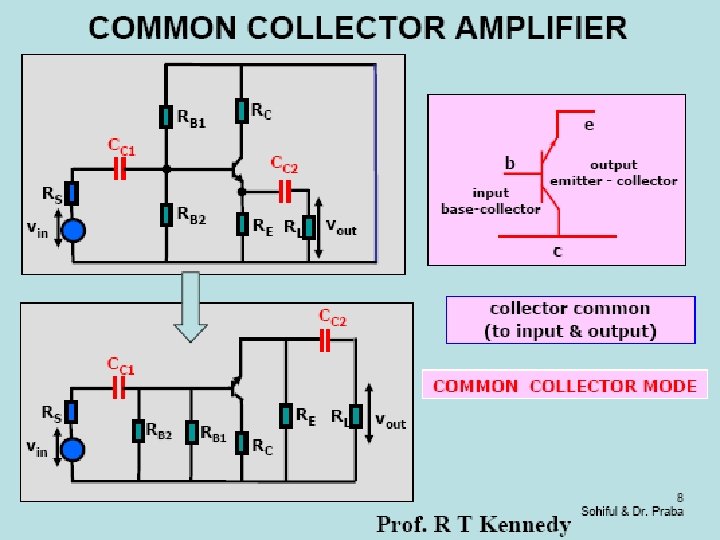
COMMON-COLLECTOR AMPLIFIER Collector connected directly to Vcc Output signal taken at emitter with respect to ground Emitter-follower circuit

COMMON-COLLECTOR AMPLIFIER Small-signal equivalent circuit of emitter-follower: Vcc or collector terminal is at signal ground. o/p resistance, ro parallel with dependent current source.

COMMON-COLLECTOR AMPLIFIER - Small-signal Analysis: Voltage Gain Assume CC is short-circuited. ro parallel with dependent current source and collector terminal is at ground. Rearrange the previous circuit so that all signal grounds connected are at same point, we will get. .

COMMON-COLLECTOR AMPLIFIER n We can also write Vo can be written as n Where Using KVL around the base -emitter loop n Combine the equations above, the small-signal voltage gain is Wee see that Or

COMMON-COLLECTOR AMPLIFIER -Input and Output Impedance: Input resistance looking into the base, Rib is given by: Since Ie is (1+β) times Ib, the effective impedance in emitter is multiplied by (1+β). This multiplication is known as resistance reflection rule. Input resistance at the base, Rib is: rπ + [effective resistance in emitter x (1+β)]

COMMON-COLLECTOR AMPLIFIER To find o/p resistance, assume input signal source, Vs is ideal and Rs=non-zero. Refer to below figure, we can determine o/p resistance looking back into o/p terminals. Set independent voltage source, Vs=0 (short circuit).

COMMON-COLLECTOR AMPLIFIER A test voltage, Vx is applied to o/p terminal and produce test current, Ix. The control voltage, Vπ is not zero, but is a function of test voltage. The output resistance, Ro is given by: Summing current at the o/p node, we have: Control voltage in term of test voltage using voltage divider:

COMMON-COLLECTOR AMPLIFIER Substitute the above eq and rearrange leads to: Note that, gmrπ=β, we find that: Or

COMMON-COLLECTOR AMPLIFIER - Small-signal Analysis: Current Gain Small-signal equivalent circuit of emitter-follower:

COMMON-COLLECTOR AMPLIFIER -Determine current gain using input resistance and concept of current divider. Current gain -Using current divider, we write base current in term of input current:

COMMON-COLLECTOR AMPLIFIER Since gm. Vπ=βIb, then Write Ie in term of Io produces Combine all equations yield to: If R 1||R 2 >> Rib and ro>>RE, then Ai (1+ )

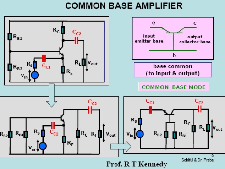
COMMON-BASE AMPLIFIER Assume load is connected to output through coupling capacitor, Cc 2. Common-base circuit -Dc analysis same as CE -Ac analysis utilizing hybrid-π equivalent circuit -Base is at signal ground, input signal applied to emitter -The o/p resistance, ro assumed to be infinite

COMMON-BASE AMPLIFIER Hybrid-π model for npn transistor with ro=∞ Small-signal equivalent circuit

COMMON-BASE AMPLIFIER - Small-signal Analysis: Voltage and Current Gain Voltage gain If RS approaches zero, then Av = gm(RC||RL) Current gain If RE approaches infinity and RL approaches zero, then short-circuit current gain

COMMON-BASE AMPLIFIER - Small-signal Analysis: Impedance Input resistance Rie Ii Ib Ri = re =

COMMON-BASE AMPLIFIER - Small-signal Analysis: Impedance Output resistance Ro Ix Ro = R C Vx

We will continue the frequency response for common-collector and common base next week SEE YA!
- Slides: 20