EMBEDDED SYSTEMS CHAPTER 2 THE TYPICAL EMBEDDED SYSTEM

EMBEDDED SYSTEMS CHAPTER 2 THE TYPICAL EMBEDDED SYSTEM

INDEX 1. Core of embedded systems • General purpose and domain specific processor. • Microprocessors • Microcontrollers. • Digital signal processors • Application Specific Integrated Circuits. (ASIC) • Programmable logic devices(PLD’s) • Commercial off-the-shelf components(COTs) 2. Memory 3. Sensors & Actuators 4. Communication Interface 5. Embedded Firmware 6. Other System Components

ELEMENTS OF AN EMBEDDED SYSYTEM. MEMORY I/P PORTS SYSTEM CORE OTHER DEVICES FIRMWARE O/P PORTS

• Embedded hardware/software systems are basically designed to regulate a physical variable or to manipulate the state of some devices by sending some signals to the actuators or devices connected to the O/P port system, in response to the input signal provided by the end users or sensors which are connected to the input ports. • Hence the embedded systems can be viewed as a reactive system. • Keyboards, push button, switches, etc. are example of common user interface input devices. • LED’s, liquid crystal displays, piezzo electrical buzzers, etc. are examples of common user interface output devices for a typical embedded systems.

5 • Some embedded systems do not require any manual interventions for their operations. • The memory of the system is responsible for holding the control algorithm and other important configuration details. • An embedded system without the control algorithm implemented memory, ie. having all the peripherals but not capable of making decissions depending on the situational as well as real world changes. • In a controller based embedded system, the controller may contain internal memory for storing control algorithm. • Such controllers are called controllers with on-chip ROM, eg. Atmel AT 89 C 51.

CORE OF THE EMBEDDED SYSTEM. Embedded systems are domain and application specific and are built around a central core. The core of the embedded system falls into any of the following categories. CORE: 1. General purpose and Domain Specific Processors 1. 1. Microprocessors 1. 2. Microcontrollers 1. 3. Digital Signal Processors 2. Application Specific Integrated Circuits. (ASIC’s) 3. Programmable logic devices(PLD’s) 4. Commercial off-the-shelf components(COTs)

GENERAL PURPOSE AND DOMAIN SPECIFIC PROCESSORS. • Almost 80% of the embedded systems are processor/ controller based. • The processor may be microprocessor or a microcontroller or digital signal processor, depending on the domain and application.

MICROPROCESSOR. q A microprocessor is a silicon chip representing a central processing unit. q A microprocessor is a dependent unit and it requires the combination of other hardware like memory, timer unit, and interrupt controller, etc. for proper functioning. q DEVELOPERS OF MICROPROCESSORS. ü Intel – Intel 4004 – November 1971(4 -bit). ü Intel – Intel 4040. ü Intel – Intel 8008 – April 1972. ü Intel – Intel 8080 – April 1974(8 -bit). ü Motorola – Motorola 6800. ü Intel – Intel 8085 – 1976. ü Zilog - Z 80 – July 1976. q Architectures used for processor design are Harvard or Von. Neumann. q RISC and CISC are the two common Instruction Set Architectures (ISA) available for processor design.

GENERAL PURPOSE PROCESSOR vs. APPLICATION SPECIFIC INSTRUCTION SET PROCESSOR. q A general processor is a processor designed for general computational tasks. q Application specific instruction set processors(ASIPs)are processors with architecture and instruction set optimized to specific-domain/application requirements like network processing, automotive, control applications, etc. q The need for an ASIP arises when the traditional general purpose processor are unable to meet the increasing application needs. q Most of the embedded systems are built around application specific instruction set processor.

MICROCONTROLLERS q A microcontroller is a highly integrated chip that contains a CPU, scratch pad RAM, special and general purpose register arrays, on chip ROM/FLASH memory for program storage , timer and interrupt control units and dedicated I/O ports. q Texas Instrument’s TMS 1000 Is considered as the world’s first microcontroller. q Some embedded system application require only 8 bit controllers whereas some requiring superior performance and computational needs demand 16/32 bit controllers. q The instruction set of a microcontroller can be RISC or CISC. q Microcontrollers are designed for either general purpose application requirement or domain specific application requirement.
, which is")
MICROPROCESSOR V/S MICROCONTROLLER Microprocessor A silicon chip representing a central processing unit(CPU), which is capable of performing arithmetic as well as logical operations according to a pre-defined set of instructions. It is a dependent unit. It requires the combination of other chips like timers, program etc. for functioning. Microcontroller Most of the time general purpose in design and operation. A microcontroller is a highly integrated chip that contains CPU , scratchpad RAM, special and general purpose register arrays, on chip ROM/FLASH memory for program storage, timer and interrupt control units and dedicated I/O ports. It is a self-contained unit and it doesn’t require external interrupt controller, timer, UART, etc. for functioning. Mostly application-oriented or domain-specific

Microcontroller Microprocessor Doesn’t contains a built in I/O port. The I/O port functionality needs to be implemented with the help of external programmable peripheral interface chips like 8255. Targeted for high end market where performance is important. It saves less power as compared to microcontroller. Most of the processors contain multiple built-in I/O ports which can be operated as a single 8 or 16 or 32 bit port or as individual port pins. Targeted for embedded market where performance is not important. It saves more power.
 q q q DSP are powerful special purpose 8/16/32 bit microprocessor")
DIGITAL SIGNAL PROCESSOR(DSP) q q q DSP are powerful special purpose 8/16/32 bit microprocessor designed to meet the computational demands and power constraints of today’s embedded audio, video and communication applications. DSP are 2 to 3 times faster than general purpose microprocessors in signal processing applications. This is because of the architectural difference the two. DSPs implement algorithms in hardware which speeds up the execution whereas general purpose processor implement the algorithm in software and the speed of execution depends primarily on the clock for the processors.

DSP includes following key units: 1. Program memory: 2. Data memory: 3. Computational engine: 4. I/O unit: 5. Calculations

1. Program memory: It is a memory for storing the program required by DSP to process the data. 2. Data memory: It is a working memory for storing temporary variables and data/signal to be processed. 3. Computational engine: It performs the signal processing in accordance with the stored program memory computational engine incorporated many specialized arithmetic units and each of them operates simultaneously to increase the execution speed. It also includes multiple hardware shifters for shifting operands and saves execution time. 4. I/O unit: It acts as an interface between the outside world and DSP. It is responsible for capturing signals to be processed and delivering the processed signals. Examples: Audio video signal processing, telecommunication and multimedia applications. 5. Calculations : - SOP(Sum of Products) calculation, convolution, FFT (Fast Fourier Transform), DFT(Discrete Fourier Transform), etc are some of the operation performed by DSP.

RISC V/S CISC q q The term RISC stands for Reduced Instruction Set Computing. Atmel AVR microcontroller is an example for a RISC processor and its instruction set contain only 32 instructions. The term CISC stands for Complex Instruction Set Computing. The original version of 8051 microcontroller (eg. AT 89 C 51) is a CISC controller and its instruction set contains 255 instructions.

SOME OF THE CRITERIA OF RISC V/S CISC ARE GIVEN BELOW: CISC RISC q q It contains lesser number of instructions. Instruction pipelining and increased execution speed. Orthogonal instruction set(allows each instruction to operate on any register and use any addressing mode. Operations are performed on registers only, only memory operations are load and store. It contains greater number of instructions. Generally no instruction pipelining feature. Non-orthogonal set(all instructions are not allowed to operate on any register and use any addressing mode. Operations are performed on registers or memory depending on instruction.

CISC RISC q q Programmer needs to write more code to execute a task since instructions are simpler ones. q It is single, fixed length instruction. q q Less silicon usage and pin count. q With Harvard Architecture. q q Instructions are like macros in C language. A programmer can achieve the desired functionality with a single instruction which in turn provides the effect of using more simpler single instruction in RISC. It is variable length instruction. More silicon usage since more additional decoder logic is required to implement the complex instruction decoding. Can be Harvard or Von-Neumann Architecture.

HARVARD V/S VON-NEUMANN ARCHITECTURE q The term Harvard and Von-Neumann refers to the processor architecture design. q Harvard architecture have separate data bus and instruction bus. q Von-Neumann architecture shares single common bus for fetching both instructions and data. q It was developed by the Princeton University and so it is referred as Princeton architecture.

Harvard v/s Von-Neumann Architecture Harvard architecture It has separate buses for instruction and data fetching. Easier to pipeline, so high performance can be achieve. It shares single common bus for instruction and data fetching. Low performance as compared to Harvard architecture. Comparatively high cost. It is cheaper. No memory alignment problems. Allows self modifying code. Since data memory and program memory are stored physically in different locations, no chances for accidental corruption of program memory. Since data memory and program memory are stored physically in the same chip, chances for accidental corruption of program memory.

BIG-ENDIAN V/S LITTLE-ENDIAN PROCESSORS q q Endianness specifies the order which the data is stored in the memory by processor operations in a multi byte system. If the word length is two byte then data can be stored in 2 different ways: a) Higher order of data byte at the higher memory and lower b) order of data byte at location just below the higher memory. Lower order of data byte at the higher memory and higher order of data byte at location just below the higher memory.

q q Little-endian means lower order data byte is stored in memory at the lowest address and the higher order data byte at the highest address. For e. g, 4 byte long integer Byte 3, Byte 2, Byte 1, Byte 0 will be store in the memory as follows: q q Big-endian means the higher order data byte is stored in memory at the lowest and the lower order data byte at the highest address. For e. g. a 4 byte integer Byte 3, Byte 2, Byte 1, Byte 0 will be stored in the memory as follows:
 1) ASICs is a microchip design to perform a")
Application Specific Integrated Circuits (ASICs) 1) ASICs is a microchip design to perform a specific and unique applications. 2) Usingle chip for integrating several functions reduces the system development cost. 3) Most of the ASICs are proprietary (which having some trade name) products, it is referred as Application Specific Standard Products(ASSP). 4) As a single chip ASIC consumes a very small area in the total system. Thereby helps in the design of smaller system with high capabilities or functionalities. 5) The developers of such chips may not be interested in revealing the internal detail of it.
 1) A programmable logic device or PLD is an electronic component")
PLD(Programmable Logic Device) 1) A programmable logic device or PLD is an electronic component used to build reconfigurable digital circuits. 2) Unlike a logic gate, which has a fixed function, a PLD has an undefined function at the time of manufacture. 3) PLDs offer customers a wide range of logic capacity, features, speed, voltage characteristics. 4) PLDs can be reconfigured to perform any number of functions at any time. 5) With programmable logic devices, designers use inexpensive software tools to quickly develop, simulate and test their designs.
. CPLD(Complex Programmable Logic Device) CPLDs offer much")
PLDs having following two major types. 1). CPLD(Complex Programmable Logic Device) CPLDs offer much smaller amount of logic up to 1000 gates. 2). FPGAs(Field Programmable Gate Arrays) It offers highest amount of logic density, most features and the highest performance

Advantages of PLDs : 1. PLDs offer customer much more flexibility during the design cycle. 2. PLDs do not require long lead times for prototypes or production parts because PLDs are already on a distributors shelf and ready for shipment. 3. PLDs can be reprogrammed even after a piece of equipment is shipped to a customer
 1) A Commercial Off The Shelf product is one")
Commercial Off The Shelf Components(COTS) 1) A Commercial Off The Shelf product is one which is used 'as-is'. 2) The COTS components itself may be develop around a general purpose or domain specific processor or an ASICs or a PLDs. 3) The major advantage of using COTS is that they are readily available in the market and a developer can cut down his/her development time to a great extent 4) The major drawback of using COTS components in embedded design is that the manufacturer of the COTS component may withdraw the product or discontinue the production of the COTS at any time if rapid change in technology occurs.

Memory ⱡ Classification of Memory ⱡ ⱡ RAM ⱡ SRAM ⱡ DRAM ROM ⱡ PROM ⱡ EEPROM
 A sensor is a transducer device that converts energy from one form")
Sensor 1) A sensor is a transducer device that converts energy from one form to another or any measurement or control purpose. 2) A sensors acts as an input device. 3) One form of sensor technology is radio frequency identification (RFID). RFID is based on tags that contain microscopic chips used to store information about the item to which it is attached. 4) Examples: ⱡ ⱡ ⱡ Push button switch Optocoupler Keyboard
 2) 3) A actuator is a form of transducer device(mechanical or electrical)")
Actuators 1) 2) 3) A actuator is a form of transducer device(mechanical or electrical) which converts signals to corresponding physical action. Actuator acts as an output device. Actuators are devices, such as valves and switches, that perform actions such as turning things on or off or making adjustments in an operational system.
 1) LED is an important output device for visual indication")
Light Emitting Diode (LED) 1) LED is an important output device for visual indication in any embedded system 2) LED can be used as indicator for the status of various signals or situations. 3) LED is a p-n junction diode and it contains an anode and cathode. 4) For proper functioning of the LED the anode of it should be connected to +ve terminal of the supply voltage and cathode to be -ve terminal of the supply voltage A resister is used in series between the power supply and LED to limit the current throw the LED. 5)
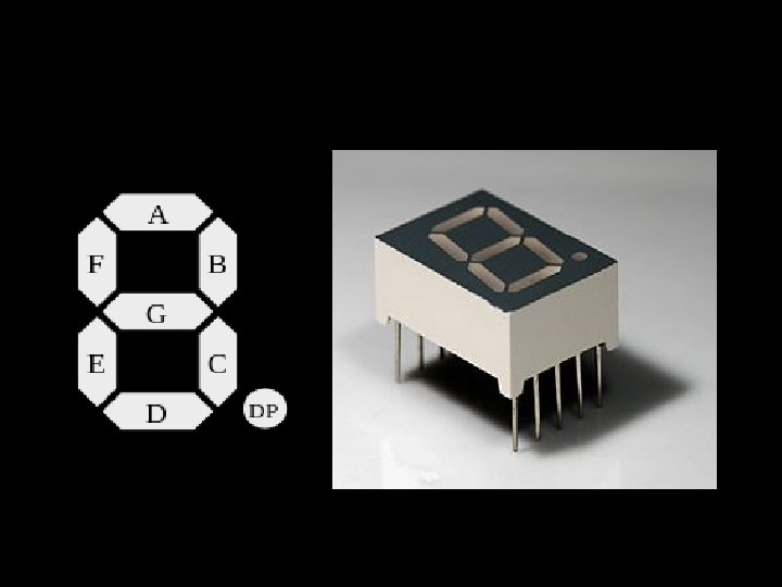
 The 7 segment LED display is an output device")
7 -segment LED display 1) The 7 segment LED display is an output device for displaying alpha numeric characters. 2) It contains 8 light emitting diodes segments arranged in a special form. 3) Out of 8 LED segments, 7 are used for displaying alpha numeric characters and 1 is used for representing decimal point in decimal number display. 4) The LED segment are named A to G and the decimal point LED segments is named as DP. 5) The LED segments A to G are should be lit accordingly to display numbers and characters. 6) For e. g. for displaying number 4 the segments F, G, B and C are lit.
 Bus Serial Peripheral Interface (SPI)")
COMMUNICATION INTERFACE Internal Communication Interface Inter Integrated Circuit(12 C) Bus Serial Peripheral Interface (SPI) Bus Universal Asynchronous Receiver Transmitter (UART) 1 -Wire Interface Parallel Interface External Communication Interface

COMMUNICATION INTERFACE Communication interface is essential for communicating with various subsystems of the embedded system and with the external world. For an embedded product , the communication interface can be viewed in two different perspectives namely: Onboard Communication Interface External Communication Interface

Onboard Communication Interfaces Internal Communication Interface is an interface which is used by Embedded system to communicate with on board components/devices. Inter Integrated Circuit(12 C) Bus Serial Peripheral Interface (SPI) Bus Universal Asynchronous Receiver Transmitter (UART) 1 -Wire Interface Parallel Interface
 Bus The Inter Integrated Circuit Bus (I 2")
Inter Integrated Circuit (I 2 C) Bus The Inter Integrated Circuit Bus (I 2 C-Pronounced ‘I square C’) is a synchronous bi-directional half duplex (one-directional communication at a given point of time) two wire serial interface bus. The I 2 C bus comprise of two bus lines , namely; (a) Serial Clock-SCL (b) Serial Data-SDA. SCL line is responsible for generating synchronization clock pulses SDA is responsible for transmitting the serial data across devices.
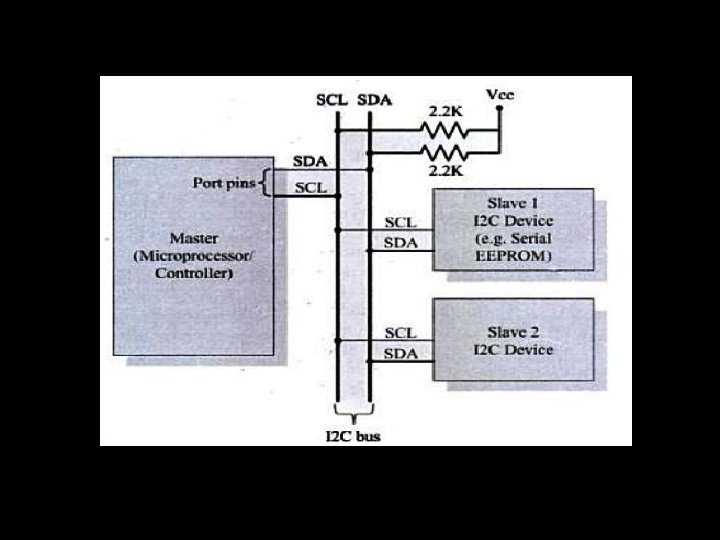

• • I 2 C bus is shared bus system to which many number of I 2 C devices can be connected. Devices connected to the I 2 C bus can act as a ‘Master Device’ or ‘Slave Device’. Master and Slave devices can act as either transmitter or receiver regardless whether a Master is acting as transmitter or receiver. The synchronization clock signal is generated by the Master device only. 3
 Bus q The Serial Peripheral Interface Bus (SPI) is a")
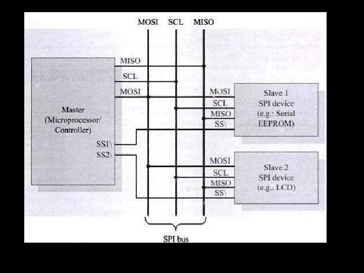
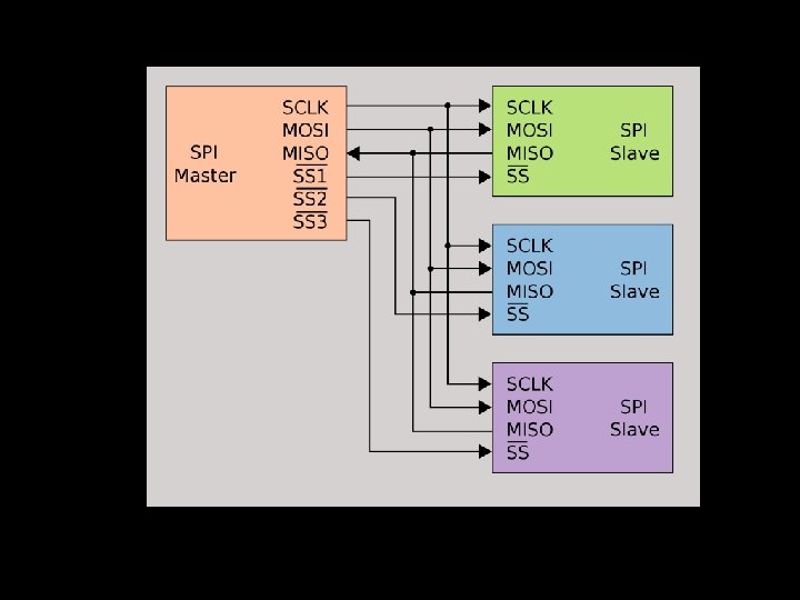
Serial Peripheral Interface (SPI) Bus q The Serial Peripheral Interface Bus (SPI) is a q q q q synchronous bi-directional full-duplex four wire serial interface bus. SPI is a single master multi-slave system. It is possible to have a system where more then one SPI device can be master , provided the condition only one master device is active at any given point of time, is satisfied. 4
: Signal line")
SPI requires four signal lines for Communication Master Out Slave In (MOSI): Signal line carrying the data from Master to Slave device It is also known as Slave input Master In Slave Out (MISO): Signal line carrying the data from Slave to Master device It is also known as Slave output. Signal line carrying the clock signal. Serial Clock (SCLK): Slave Select (SS): Signal line for slave device select. It is an active low signal.

External Communication Interface is an interface which is used by Embedded system to communicate to external world. The following sections gives an overview of the various interfaces for external communication. 1. 2. 3. 4. 5. 6. 7. 8. Recommended Standard number 232. Universal Serial Bus(USB). IEEE 1394 (Firewire) Infrared (Ir. DA) Bluetooth Wi-Fi Zig Bee General Packet Radio Service (GPRS)

Recommended Standard number 232 q q RS 232 is a legacy full duplex, wired, asynchronous serial communication interface. RS 232 extends the UART communication signals for external communication. RS 232 follows the EIA standard for bit transmission. As per the EIA standard a logic 0 is represented with voltage between 3 to 25 and a logic 1 is represented with voltage between 3 to 25. RS 232 supports two different types of connectors namely: DB 9(9 pin connector) and DB 25(25 pin connector).
 q q q USB is a wired high speed serial")
Universal Serial Bus (USB) q q q USB is a wired high speed serial interface for data communication. USB communication follows the star topology with a USB host at the center and USB transmits data in packet format. Each data packet has a standard format. The USB host contain a controller which is responsible for controlling the data communication including establishing connectivity with USB slave devices. The physical communication between a USB peripheral device and master device is established with a USB cable.

q q The USB cable supports communication distance of up to 5 meters. The USB standards uses two different types of connector at the ends of the cable for connecting the USB peripheral device and host device TYPE A connector is used for upstream connection(connection with host) TYPE B connector is used for downstream connection(connection with slave device). Star topology Source: http: //www. l-com. com/what-is-ausb-cable

Star topology Source: http: //www. l-com. com/what-is-a-usb-cable

q Data Transfer Types q q q Control transfer is used by system software to query configure issue commands to the USB device. Bulk transfer is used for sending a block of data to a device. Isochronous data transfer is used for real-time data communication Interrupt is used for transferring small amount of data. USB supports four different data rates namely: Low speed(1. 5 mbps), Full speed(12 mbps), High speed(480 mbps), Super speed(4. 8 Gbps).

Embedded Firmware ⱡ ⱡ Control algorithm and or the configuration settings that are stored into the program memory of the embedded system. Essential part of embedded system. Methods for development of embedded firmware ⱡ Write a high level program and use IDE (containing editor, compiler, linker, debugger, simulator etc). This process is called ‘hex file creation. ’ ⱡ Write assembly language program using instruction supported by controller or processor used in the application. Embedded programs are written using one of the following two approaches ⱡ Super loop approach ⱡ Function scheduler approach.

Other System Components ⱡ ⱡ ⱡ Reset Circuit Brown – out protection circuit Oscillator unit Real time clock Watchdog Timer PCB and Passive components

THANK YOU
- Slides: 52