Embedded Computing Processors CSE 237 D Winter 2010

Embedded Computing Processors CSE 237 D: Winter 2010 Topic #6 Ryan Kastner

What kind of embedded processor? v What are our options for processors in embedded systems? v What performance metrics are we worried about?

“Traditional” Software Embedded Systems = CPU + RTOS Slide courtesy of Mani Srivastava

“Traditional” Hardware Embedded Systems = ASIC Features Area: 4. 6 mm x 5. 1 mm Speed: 20 MHz @ 10 Mcps Technology: HP 0. 5 m Power: 16 m. W - 120 m. W (mode dependent) @ 20 MHz, 3. 3 V Avg. Acquisition Time: 10 s to 300 s A direct sequence spread spectrum (DSSS) receiver ASIC Source: Mani Srivastava

A spectrum of options now v Microcontroller v Microprocessor v ASIP v DSP v Graphics Processor v Network Processor v Cryptoprocessor v… v FPGA v ASIC
 is a small, lightweight CPU which is")
Microcontrollers Overview v A microcontroller (u. C) is a small, lightweight CPU which is usually combined with on-board memory and peripherals v v Compact and low power (relatively) Often used as a simple hardware to software interface as well as for in-situ processing v v Analog to digital gateway Allows for real-time feedback based on data sensor Microcontroller (u. C) Digital to Analog sensor Analog to Digital sensor actuator indicator

Microcontroller Features v Processor speed: Fundamental measure of processing rate of device v Value of interest is in MIPS, not MHz v Supply voltage/current: Measure of the amount of power required to run the device v Multiple v It modes (sleep, drowsy, idle, etc) is possible to adjust the voltage and frequency of some devices in real time, thereby trading off speed and power usage

Microcontroller Features v Internal memory: Sometimes divided between program and data memory, the amount of information that can be stored on board v v I/O Pins: Individual points for communication between the u. C and the rest of the world v v Can be supplemented with external memory Can be digital or analog, general or special purpose Interrupts: Non-linear program flow based on event triggers from peripheral or pins Memory CPU ROM RAM I/O Subsystems: Timers, Counters, Analog Interfaces, I/O interfaces
 in the u. C that increment")
Microcontroller Peripherals v Timers: Internal registers (any size) in the u. C that increment at the clock rate v Voltage Comparators: Input that effectively functions as a 1 -bit ADC with an adjustable threshold v ADC: Most ADCs used in sensor data collection are integrated with u. C v DAC: Digital to analog converters are also included in some data collection driven u. C v Mostly used for feedback and control
 v")
Microcontrollers Communication v UART: Basic hardware module which mediates serial communication (RS 232) v v v Simplest form of communication but limited by speed Most modules are full duplex USB: High bandwidth serial communication between u. C and a computer or an embedded host v Usually requires chips with specialized hardware and firmware Host side issues v v I 2 C: v v Half duplex master-slave 2 -wire protocol for data transfer kbit transfer rates Tx/Rx based on slave addressing Can invert protocol with sensors as masters RF: Radio frequency (>100 MHz) EM transmission of data v v Built in to some newer special-purpose u. C Wireless spherical transmission

8051 Architecture

PIC Architecture

AVR v 8 -bit RISC series of microcontroller chips Large range of available devices covering many interfaces, speeds, memory sizes, and package sizes v Large hobbyist development community with many available free tool chains and sample applications v v General specs One MIPS per MHz v Models available up to 20 MHz v Max 128 K program space / 8 K RAM v ADC/LCD Driver/Motor Control v UART/CAN/USB/I 2 C/SPI/DAC/LCD/PWM/Comparators v v http: //www. atmel. com/products/product_selector. asp

TI MSP 430 v Proprietary TI low-power low-cost RISC chips v Well supported by TI with good program chain v Designed for intermittent sampling and fast startup v General specs v Very low power (flexible) v Max 32 KHz / 8 MIPS v Max 50 K program space / 10 K RAM v Max 16 bit ADC v UART/SPI/DAC/LCD/PWM/Comparators v http: //www. msp 430. com

Atmel ARM 7 v 32 -bit ARM microcontroller v Low power (for 32 -bit machines) v Can run in 16 -bit mode if needed v General specs v Lots of memory (8 -64 KB RAM, 32 -256 KB flash) v Variable speed up to 55 MHz v Packed with peripherals (USB, ADC, SPI, etc. ) v Common in systems that require more processing v http: //www. at 91. com/

Many Types of Programmable Processors n Past u Microprocessor u Microcontroller u DSP u Graphics Processor n Now / Future u Network Processor u Sensor Processor u Cryptoprocessor u Game Processor u Wearable Processor u Mobile Processor Source: Mani Srivastava

From Processor to ASIP Decoder RF 0 Control Source FU 0 Spatial bottleneck: not enough bandwidth Temporal bottleneck: Limited functionality Result Source: Tensilica

Add Custom Functional Units Decoder RF 0 Control Source routing FU 0 FU 1 FU 2 FU 3 Result routing Source: Tensilica

Customize Memory Decoder RF 0 RF 1 S 0 RF 2 S 1 Control Source routing FU 0 FU 1 FU 2 FU 3 Result routing Source: Tensilica

Multicycle Instructions Decoder RF 0 RF 1 S 0 RF 2 S 1 Control Source routing FU 0 FU 1 FU 2 FU 3 Result routing Source: Tensilica

Tensilica Xtensa Processor Options Base ISA Feature Configurable Function Optional & Configurable Advanced Designer Defined Coprocessors Instruction Fetch / PC Unit MMU ITLB Instruction Cache Instruction ROM Instruction RAM External Interface Write Buffer (1 to 32 entries) Data Load / Store Unit Xtensa Processor Interface (PIF) MMU DTLB DTL TLB Data Cache Data ROM Data RAM Source: Tensilica

ASIP Design Flow I/O ALU Pipe Cache Register File Describe new instructions MMU Tailored, synthesizable HDL u. P core Select processor options (FU, $, Registers, etc) ******* *** Timer Use automated processor generator, create custom processor Customized Compiler, Assembler, Linker, Debugger, Simulator Source: Tensilica
 level v")
Architectural Design Space v Approaches to Parallel Processing v Processing Element (PE) level v Instruction-level v Bit-level v Elements of Special Purpose Hardware v Structure of Memory Architectures v Types of On-Chip Communication Mechanisms v Use of Peripherals
 SRAM (Routing table) Bus Output ports")
Typical Network Processor Architecture SDRAM Bus (Packet buffer) SRAM (Routing table) Bus Output ports Input ports multi-threaded processing elements Co-processor Network Processor

Intel IXP 1200 Network Processor ° Strong. ARM processing core ° Microengines introduce new ISA ° I/O • PCI • SDRAM • SRAM • IX : PCI-like packet bus ° On chip FIFOs • 16 entry 64 B each

Intel IXP 1200 Microengine n 4 hardware contexts n n n Registers n n n n Can access GPR or XFER registers Shared hash unit n n All are single ported Separate GPR 256*6 = 1536 registers total 32 -bit ALU n n Single issue processor Explicit optional context switch on SRAM access 1/2/3 values – 48 b/64 b For IP routing hashing Standard 5 stage pipeline 4 KB SRAM instruction store – not a cache! Barrel shifter

IBM Power. NP v v v 16 pico-processors and 1 Power. PC v Each pico-processor support 2 hardware threads v 3 stage pipeline : fetch/decode/execute Dyadic Processing Unit v Two pico-processors v 2 KB Shared memory v Tree search engine Focus is Network layers 2 -4 Power. PC 405 for control plane operations v 16 K I and D caches Target is OC-48

Cisco 10000 v v Almost all data plane operations execute on the programmable XMC Pipeline stages are assigned tasks – e. g. classification, routing, firewall, MPLS v v Classic SW load balancing problem External SDRAM shared by common pipe stages

Summary: ASIPs n Processors with instruction-sets tailored to specific applications or application domains F Instruction-set generation as part of synthesis F Customized processor options n Pluses: F Customization n yields lower area, power etc. Minuses: F higher h/w & s/w development overhead – design, compilers, debuggers – higher time to market Source: Mani Srivastava

What is this? 90 nm 9 -layer Interconnect (from Altera Source: Altera

What is this? Dielectric Contact Salicide Spacer Poly Spacer Isolation Diffusion 90 nm Transistor (from Altera FPGA) Source: Altera

FPGA

FPGA CLB Switchbox Routing Channel Configuration Bit IOB

Programmable Logic Tracks Logic Element LE LE LE v. Each logic element outputs one data bit v. Interconnect programmable between elements v. Interconnect tracks grouped into channels
 v Program configuration bits for required A functionality v Computes “any”")
Lookup Table (LUT) v Program configuration bits for required A functionality v Computes “any” 2 -input B function 2 -LUT In 00 01 10 11 Out 0 0 0 1 Configuration Bit 0 Configuration Bit 1 C Configuration Bit 2 Configuration Bit 3 A B C=A B
 v K-LUT -- K input lookup table v Any function of")
Lookup Table (LUT) v K-LUT -- K input lookup table v Any function of K inputs by programming table v Load bits into table v 2 N bits to describe functions v => different functions
 K-LUT (typical k=4) w/ optional output Flip-Flop")
Lookup Table (LUT) K-LUT (typical k=4) w/ optional output Flip-Flop
 v Single v LUT configuration bit for each: bit v Interconnect")
Lookup Table (LUT) v Single v LUT configuration bit for each: bit v Interconnect point/option v Flip-flop select
")
Configurable Logic Block (CLB)

Programmable Interconnect v Interconnect architecture Fast local interconnect v Horizontal and vertical lines of various lengths v C L B CL B Switch Matrix CL B

Switchbox Operation Before Programming v v v 6 pass transistors per switchbox interconnect point Pass transistors act as programmable switches Pass transistor gates are driven by configuration memory cells After Programming

Programmable Interconnect

Programmable Interconnect 25

Embedded Functional Units Fixed, fast multipliers v MAC, Shifters, counters v Hard/soft processor cores v Power. PC v Nios v Microblaze v v Memory Block RAM v Various sizes and distributions v

Embedded RAM v Xilinx – Block Select. RAM v 18 Kb v Altera dual-port RAM arranged in columns – Tri. Matrix Dual-Port RAM v M 512 – 512 x 1 v M 4 K – 4096 x 1 v M-RAM – 64 K x 8

Xilinx Virtex-II Pro v v v Up to 16 serial transceivers • 622 Mbps to 3. 125 Gbps Power. PCs v 1 to 4 Power. PCs 4 to 16 multi-gigabit transceivers 12 to 216 multipliers 3, 000 to 50, 000 logic cells 200 k to 4 M bits RAM 204 to 852 I/Os Logic cells

Altera Stratix

FPGA Architectures v FPGA-based reconfigurable devices v Configurable logic blocks v Flexible logic block v Programmable interconnect v v Dedicated multipliers Embedded configurable block RAM RISC microprocessor cores Other architectures v v Reconfigurable multi-core processor Coarse-grained reconfigurable architectures
 v Full v v Custom ASICs Every transistor is")
Application Specific Integrated Circuits (ASICs) v Full v v Custom ASICs Every transistor is designed and drawn by hand Typically only way to design analog portions of ASICs Gives the highest performance but the longest design time Full set of masks required for fabrication Source: Paul D. Franzo
 v Standard-Cell-Based ASICs v v or ‘Cell Based IC’")
Application Specific Integrated Circuits (ASICs) v Standard-Cell-Based ASICs v v or ‘Cell Based IC’ (CBIC) or ‘semi-custom’ Standard Cells are custom designed and then inserted into a library These cells are then used in the design by being placed in rows and wired together using ‘place and route’ CAD tools Some standard cells, such as RAM and ROM cells, and some datapath cells (e. g. a multiplier) are tiled together to create macrocells D-flip-flop: NOR gate: Source: Paul D. Franzo

Standard Cells N Well VDD Cell height 12 metal tracks Metal track is approx. 3 + 3 Pitch = repetitive distance between objects Cell height is “ 12 pitch” 2 Cell boundary In Out GND Rails ~10 © Digital Integrated Circu

Standard Cells VDD A 2 -input NAND gate B Out GND © Digital Integrated Circu

Standard Cell Layout Methodology – 1980 s Routing channel VDD signals GND © Digital Integrated Circu

Standard Cell Layout Methodology – 1990 s Mirrored Cell No Routing channels VDD M 2 M 3 GND Mirrored Cell GND © Digital Integrated Circu

Standard Cell Layouts

ASIC Design Flow Most ASICs are designed using a RTL/Synthesis based methodology Design details captured in a simulatable description of the hardware • Captured as Register Transfer Language (RTL) • Simulations done to verify design Source: Paul D. Franzo

ASIC Design Flow Automatic synthesis is used to turn the RTL into a gatelevel description • ie. AND, OR gates, etc. • Chip-test features are usually inserted at this point Gate level design verified for correctness Output of synthesis is a “net-list” • i. e. List of logic gates and their implied connections NOR 2 U 36 (. Y(n 107), . A 0(n 109), . A 1(value[2] ) ); NAND 2 U 37 (. Y(n 109), . A 0(n 105), . A 1(n 103) ); NAND 2 U 38 (. Y(n 114), . A 0(value[1] ), . A 1(value[0] ) ); NOR 2 U 39 (. Y(n 115), . A 0(value[3] ), . A 1(value[2] ) ); Source: Paul D. Franzo

ASIC Design Flow Physical Design tools used to turn the gate-level design into a set of chip masks (for photolithography) or a configuration file for downloading to an FPGA Floorplanning • Positioning of major functions Placement • Gates arranged in rows

ASIC Design Flow Clock and buffer Insertion • Distribute clocks to cells and locate buffers for use as amplifiers in long wires Routing • Logic Cells wired together
")
Semiconductor Roadmap Projections for ‘leading edge’ ASIC: (www. itrs. net)
 45 40 35 30")
Std Cell ASIC Development Cost Trend Total Development Costs ($M) 45 40 35 30 25 20 15 10 5 0 0. 18 µm 0. 15 µm 0. 13 µm Masks & Wafers Software 90 nm 65 nm 45 nm Test & Product Engineering Design/Verification & Layout Note: Conservative estimate; does not include re-spins.

Result: Declining ASIC Starts 12000 Standard Cell/Gate Arrays Design Starts 10000 8000 6000 4000 2000 0 1996 1997 1998 1999 2000 2001 2002 2003 2004 2005 2006 2007 Source: Dataquest/Gartner

FPGA vs Standard Cell Parameter FPGA Standard Cell CAD tool Cost $2000 $Millions Mask Cost 0 $1. 4 M US @ 90 nm Bug Fix 1 hour ~10 weeks Electrical & Optical Check & Debug Vendor’s Problem Your Problem! Time to Market Fast Slow Die Size 2 X to 20 X 1 X Volume Cost 1 X to 20 X 1 X Speed 0. 3 X to 0. 6 X 1 X Power 2 X to 5 X 1 X 63 Source: Altera

Efficiency vs. Development Cost High Power & System Cost* Development Difficulty & Cost Low Processor DSP FPGA Struct. ASIC Std. Cell Full Custom *For applications with significant parallelism Source: Altera

Many Implementation Choices Speed Power Cost Microprocessors/controllers v ASIP v DSP v Graphics v Network processors v Crypto v FPGA v ASIC v High Low Volume

Embedded System Design v CAD tools take care of hardware fairly well v Although v But, a productivity gap emerging software is a different story… v HLLs such as C help, but can’t cope with complexity and performance constraints Holy Grail for Tools People: H/W-like synthesis & verification from a behavior description of the whole system at a high level of abstraction using formal computation models Source: Mani Srivastava

Productivity Gap in Hardware Design A growing gap between design complexity and design productivity Source: Alberto Sangiovanni-Vincentel

Situation Worse in S/W Billion $/Year Do. D Embedded System Costs Source: Mani Srivastava

Embedded System Design from a Design Technology Perspective v Intertwined subtasks Specification/modeling v H/W & S/W partitioning v Scheduling & resource allocations v H/W & S/W implementation v Verification & debugging v v Crucial is the co-design and joint optimization of hardware and software Source: Mani Srivastava

On-going Paradigm Shift in Embedded System Design v Change in business model due to So. Cs v v Component-based design v v Currently many IC companies have a chance to sell devices for a single board In future, a single vendor will create a System-on-Chip But, how will it have knowledge of all the domains? Components encapsulate the intellectual property Platforms v v v Integrated HW/SW/IP Application focus Rapid low-cost customization Source: Mani Srivastava

Complexity and Heterogeneity controller processes control panel ASIC DSP Assembly Code Real-time OS controller Programmable DSP Dual-ported RAM v UI processes DSP Assembly Code CODEC Heterogeneity within H/W & S/W parts as well v v S/W: control oriented, DSP oriented H/W: ASICs, COTS ICs Source: Mani Srivastava

Handling Heterogeneity Source: Edward Lee

IP-based Design Source: Mani Srivastava

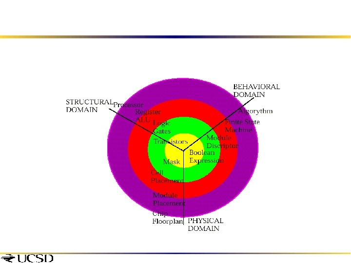
Map from Behavior to Architecture Source: Mani Srivastava

Behavior Vs. Architecture Models of Computat ion Performance models: Emb. SW, comm. and comp. resources 1 System Behavior Simulation Synthesis System 2 Architecture HW/SW partitionin g, Schedulin g SW estimation Mapping 3 Performance Simulation Communication Refinement 4 Flow To Implementation Source Alberto Sangiovanni-Vincentell

Hardware vs. Software Modules Hardware = functionality implemented via a custom architecture (e. g. datapath + FSM) v Software = functionality implemented in software on a programmable processor v Key differences: v v Multiplexing v software modules multiplexed with others on a processor v e. g. using an OS v hardware modules are typically mapped individually on dedicated hardware v Concurrency v processors usually have one “thread of control” v dedicated hardware often has concurrent datapaths Source: Mani Srivastava

Hardware-Software Architecture v. A significant part of the problem is deciding which parts should be in software on programmable processors, and which in specialized hardware v Today: v Ad hoc approaches based on earlier experience with similar products, & on manual design v HW-SW partitioning decided at the beginning, and then designs proceed separately Source: Mani Srivastava

Extra Slides
 Source: Mani Srivastava")
Industrial Structure Shift (from Sony) Source: Mani Srivastava

Where are the CPUs? Estimated 98% of 8 Billion CPUs produced in 2000 used for embedded apps Where Has CS Focused? Interactive Computers 200 M per Year Servers, etc. Where Are the Processors? Direct 2% Robots Vehicles 6% 12% 8. 5 B Parts per Year Embedded Computers 80% In Vehicles In Robots Embedded Look for the CPUs…the Opportunities Will Follow! Source: DARPA/Intel (Tennenhouse)

PIC Data Sheet

Example: Video Processor Philips Nexperia: MIPS CPU PRxxxx TM-xxxx DEVICE I/P BLOCK. . . DEVICE I/P BLOCK TM Tri. Media CPU D$ I$ VLIW Media Processor: • 100 to 300+ MHz • 32 -bit or 64 -bit DEVICE I/P BLOCK PI BUS I$ MMI DVP MEMORY BUS D$ Tri. Media SDRAM PI BUS General Purpose RISC Processor • 50 to 300+ MHz • 32 -bit or 64 -bit Library of Device Blocks • Image coprocessors • DSPs • UART • 1394 • USB TM . . . DEVICE I/P BLOCK Nexperia System Busses • PI bus • Memory bus • 32 -128 bit • …and more DVP System Silicon Flexible architecture for digital video applications
 Source: Mani Srivastava")
Increasingly on the Same Chip: System on a Chip (SOC) Source: Mani Srivastava
 Altera’s Nios (configurable RISC")
Reconfigurable So. C Other Examples Atmel’s FPSLIC (AVR + FPGA) Altera’s Nios (configurable RISC on a PLD) Triscend’s A 7 CSo. C Source: Mani Srivastava

Reconfigurable Hardware Main Entry: re. Function: prefix 1 : again : anew <retell> 2 : backward <recall> Main Entry: con·fig·ure Pronunciation: k&n-'fi-gy&r Function: transitive verb : to set up for operation especially in a particular way CLB Block RAM IP Core (Multiplier) KEY ADVANTAGE: Performance of Hardware, Flexibility of Software
- Slides: 86