
EMail address hirokunikmail plala or jp Who am

- Slides: 30
Hirokuni Michimori E-Mail address: hirokuni@kmail. plala. or. jp
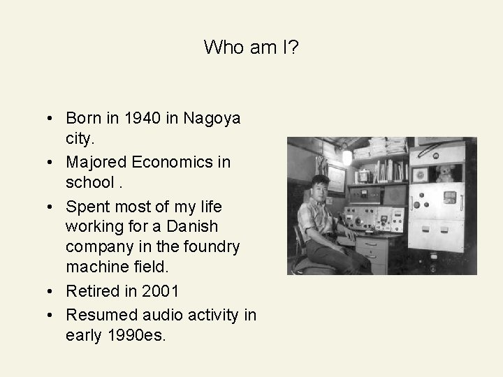
Who am I? • Born in 1940 in Nagoya city. • Majored Economics in school. • Spent most of my life working for a Danish company in the foundry machine field. • Retired in 2001 • Resumed audio activity in early 1990 es.
Why I resumed Audio activity in early 1990 es • Have got amateur radio station license JA 2 AEY 50 years ago • I built receivers and transmitters (AM) by myself using 42, 807, 6146, 829 B and 4 D 32 • Soon advanced to SSB era, built SSB generators and linear amps with such as 811 A, 813 and 4 -1000 A • Still active on Ham radio, however all of my present gears are commercially made ones, but in all semiconductors • Impossible to build quality Ham gears surpassing commercially made radios technically and financially • My last one was with Eimac 8877 some 30 years ago • Have come across a new joy to designing and building better amps sufficing my satisfaction and can enjoy hands-on assembling which has been lost in the Ham radio arena • Early 90 es, K. Sisido`s idea inspired me to involve transmitting tube amps: “Inversed inter-stage transformer drive” using zero bias
Triode Zero bias amplifiers • • • 845, 211, DA 100 and RS 237 are regarded nice sounding but difficult to acquire In early 1990 es, K. Shishido introduced a method “Inversed interstage transformer drive” for zero bias transmitting tubes available in good quality / price in the market 800, 808, 811 A, 8025 A, 826, 838, 805, 810 and 100 TH for plus bias amplifiers were discussed and contributed to MJ in ten years Direct Dynamic Coupling method was later introduced by S. Soya , advantages are 1)simplified circuitry 2)versatality, while its weakness of lower output In 2000, transformer-less (inversed inter-stage ) method was contrived by H. Michimori (presenter) and applied it to 811 A amp In a few years, the said solution has been verified by a difficult to drive tube 100 TH inclusive 838 and 8025 A successfully, then I named it “Regulator tube drive”
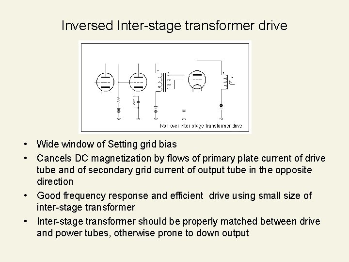
Inversed Inter-stage transformer drive • Wide window of Setting grid bias • Cancels DC magnetization by flows of primary plate current of drive tube and of secondary grid current of output tube in the opposite direction • Good frequency response and efficient drive using small size of inter-stage transformer • Inter-stage transformer should be properly matched between drive and power tubes, otherwise prone to down output
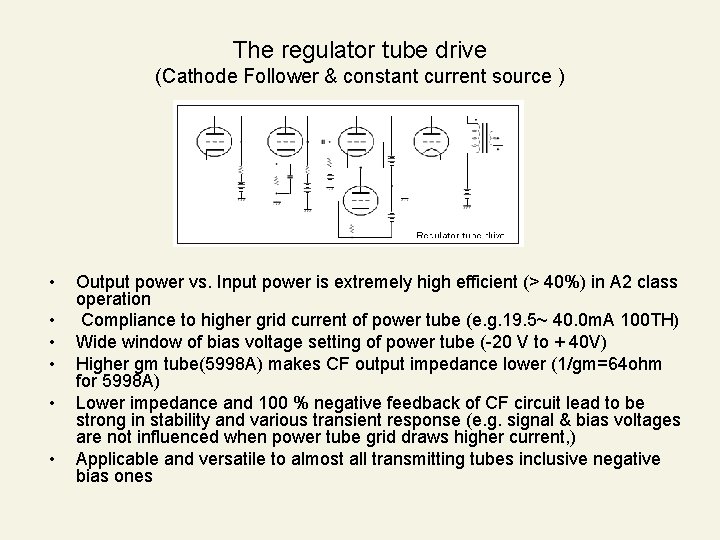
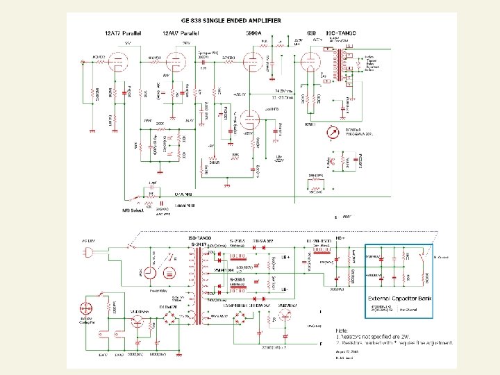
The regulator tube drive (Cathode Follower & constant current source ) • • • Output power vs. Input power is extremely high efficient (> 40%) in A 2 class operation Compliance to higher grid current of power tube (e. g. 19. 5~ 40. 0 m. A 100 TH) Wide window of bias voltage setting of power tube (-20 V to + 40 V) Higher gm tube(5998 A) makes CF output impedance lower (1/gm=64 ohm for 5998 A) Lower impedance and 100 % negative feedback of CF circuit lead to be strong in stability and various transient response (e. g. signal & bias voltages are not influenced when power tube grid draws higher current, ) Applicable and versatile to almost all transmitting tubes inclusive negative bias ones
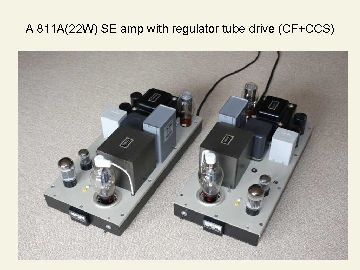
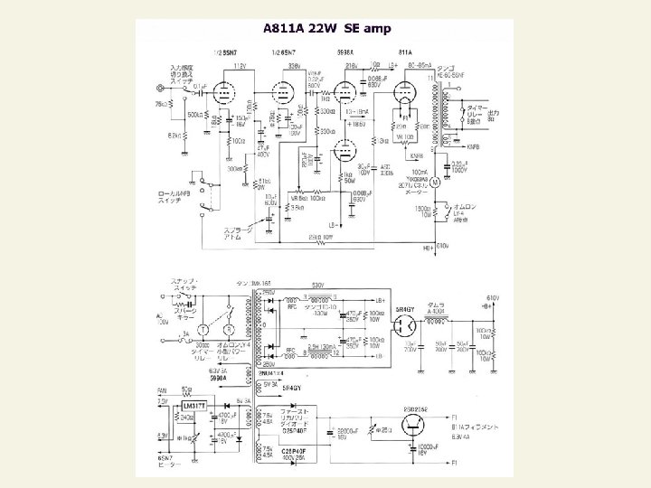
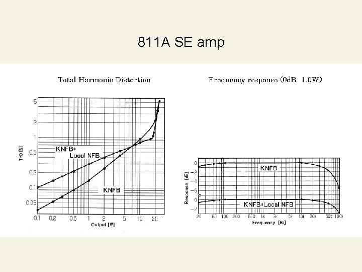
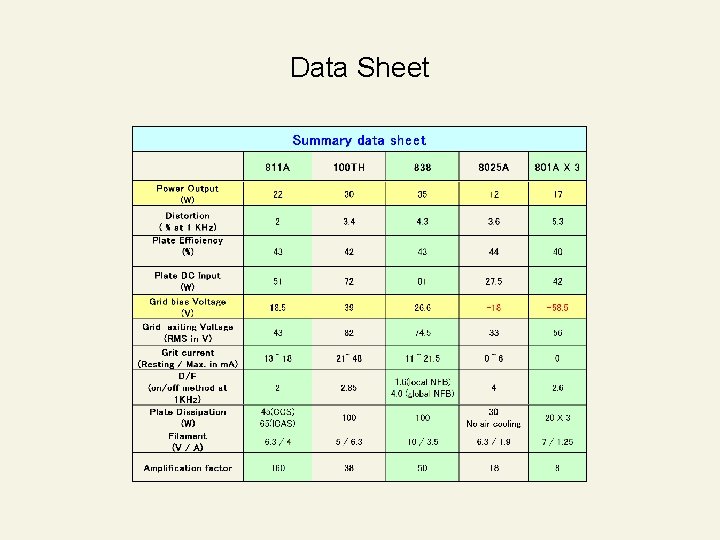
811 A SE amp • 811 A is a compact size zero-bias transmitting tube and easy to designing & assembling for Audio amplifier • Plate dissipation 65 W(ICAS), filament 6. 3 V(4 A), amplification factor 160, and generic UX socket • 600 V, 80 m. A (no signal) at plate, +18. 5 V grid bias and 85 m. A at maximum signal of 47 V rms for 22 W output in A 2 operation • Transformers (power & output) are of Ex-TANGO XE-60 -5 SNF & MX 165 • XE-60 -5 SNF possessing 5 K ohm load impedance and 36 ohm KNFB coil • KNFB coil connected to 811 A cathode to increase load impedance to ca. 5. 9 K ohm resulting dumping factor to be improved to 2. 0 from 0. 2
A 811 A(22 W) SE amp with regulator tube drive (CF+CCS)
811 A SE amp
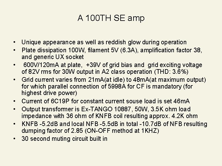
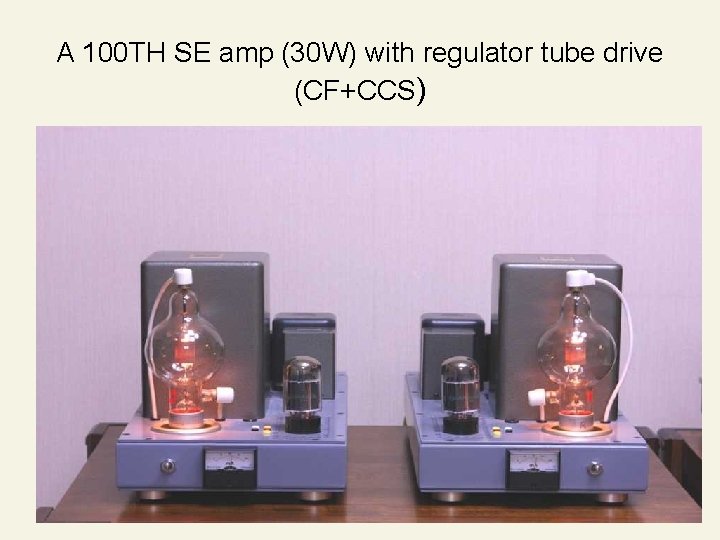
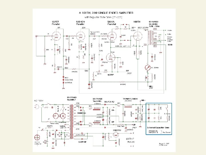
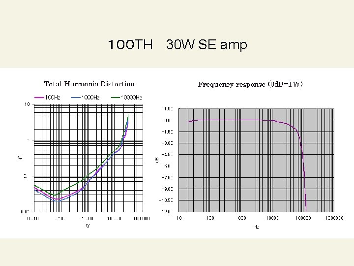
A 100 TH SE amp • Unique appearance as well as reddish glow during operation • Plate dissipation 100 W, filament 5 V (6. 3 A), amplification factor 38, and generic UX socket • 600 V/120 m. A at plate, +39 V of grid bias and grid exciting voltage of 82 V rms for 30 W output in A 2 class operation (THD: 3. 6%) • Grid current varies from 21 m. A(at idle) to 48 m. A(at maximum output) for which parallel connection of 5998 A for CF is mandatory (for highest drive power) • Current of 6 C 19 P for constant current souse load is set 46 m. A • Output transformer is Ex-TANGO 10887, 50 W, 3. 5 K ohm load impedance with 36 ohm of KNFB coil resulting approx. 4. 2 K ohm • KNFB -5. 2 d. B and local NFB -5. 5 d. B in total -10. 7 d. B of NFB resulting dumping factor of 2. 85 (ON-OFF method at 1 KHZ) • 30 second muting circuit built in
A 100 TH SE amp (30 W) with regulator tube drive (CF+CCS)
100 TH 30 W SE amp
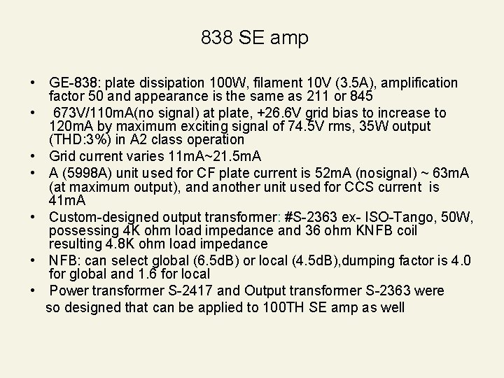
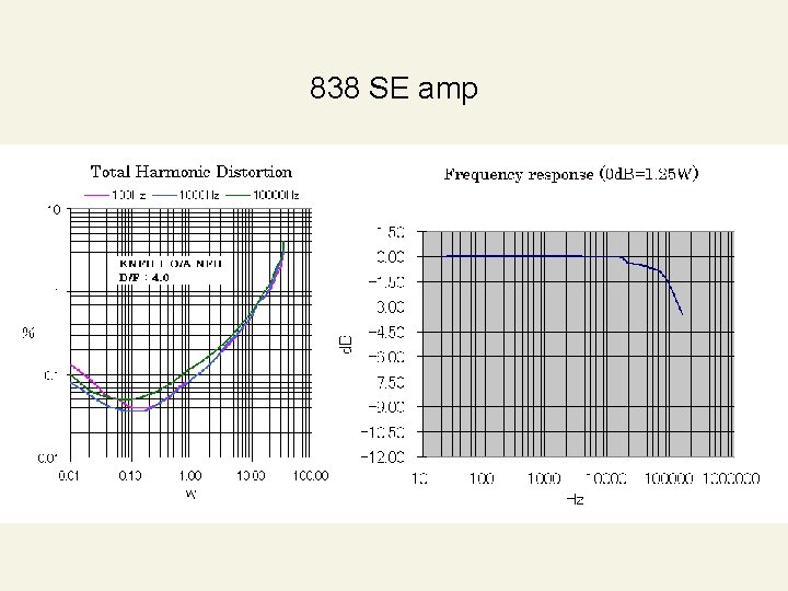
838 SE amp • GE-838: plate dissipation 100 W, filament 10 V (3. 5 A), amplification factor 50 and appearance is the same as 211 or 845 • 673 V/110 m. A(no signal) at plate, +26. 6 V grid bias to increase to 120 m. A by maximum exciting signal of 74. 5 V rms, 35 W output (THD: 3%) in A 2 class operation • Grid current varies 11 m. A~21. 5 m. A • A (5998 A) unit used for CF plate current is 52 m. A (nosignal) ~ 63 m. A (at maximum output), and another unit used for CCS current is 41 m. A • Custom-designed output transformer: #S-2363 ex- ISO-Tango, 50 W, possessing 4 K ohm load impedance and 36 ohm KNFB coil resulting 4. 8 K ohm load impedance • NFB: can select global (6. 5 d. B) or local (4. 5 d. B), dumping factor is 4. 0 for global and 1. 6 for local • Power transformer S-2417 and Output transformer S-2363 were so designed that can be applied to 100 TH SE amp as well
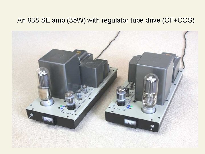
An 838 SE amp (35 W) with regulator tube drive (CF+CCS)
838 SE amp
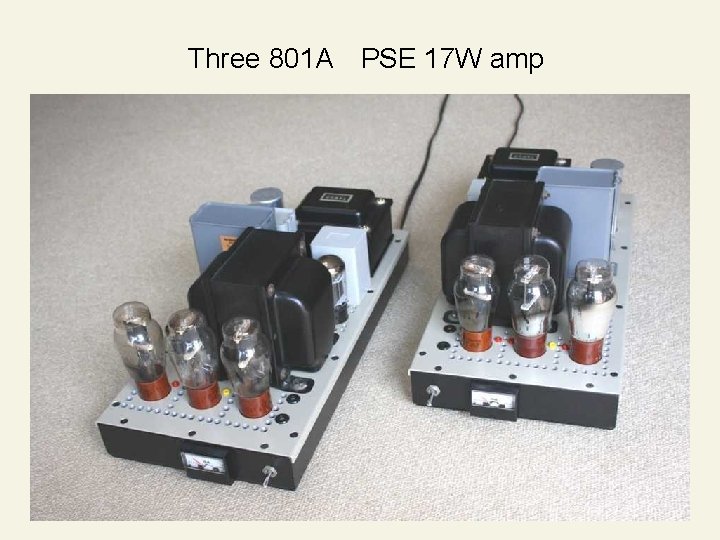
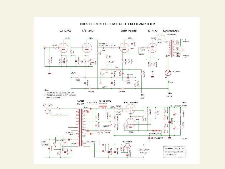
Three 801 A’s PSE 17 W amp • Designed adopting an idea from “ 801 A's parallel single ended stereo amp” appeared in “Radio Gijyutsu” on September, 1979 written by K. Takesue • 801 A: Plate dissipation 20 W, filament 7. 5 V (1. 25 A), amplification factor 8 and unique inherent linearity of average plate characteristics • Three 801 As in parallel to lower plate load resistance to 1/3 and to widen selection of output transformers keeping its unique inherent linearity • 600 V/70 m. A in A class operation with no NFB and conventional minus bias configuration to generate 17 W output • Output transformer: Magnequest FS-007 (6 K ohm)
Three 801 A PSE 17 W amp
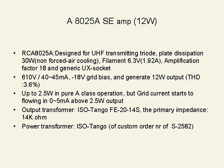
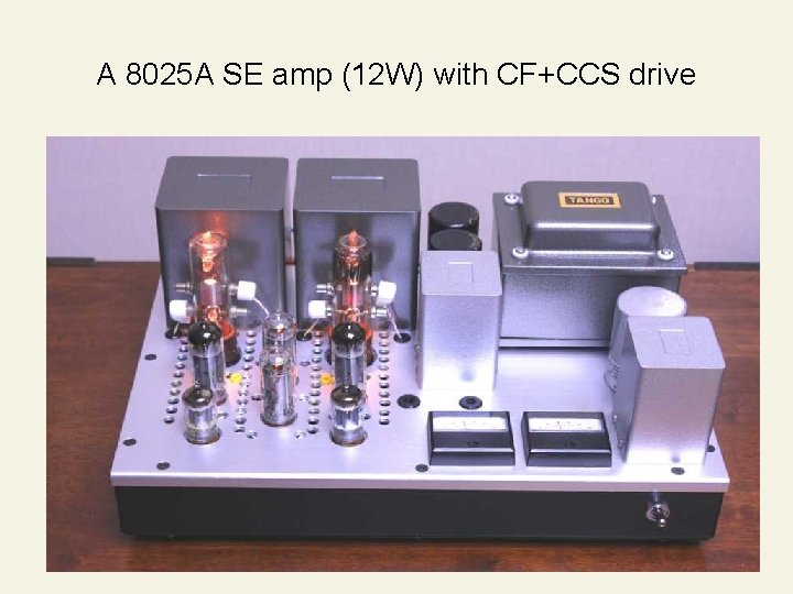
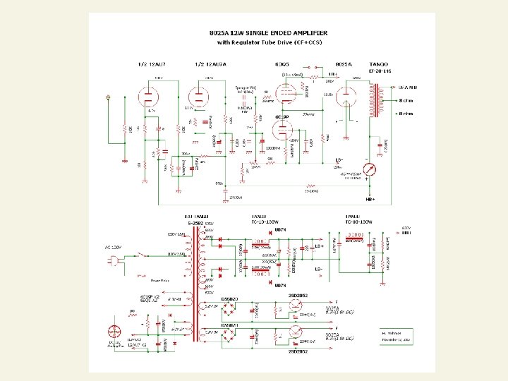
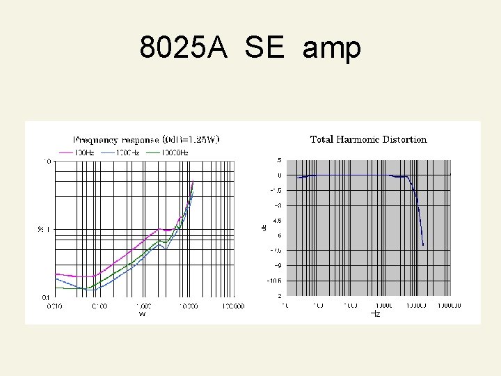
A 8025 A SE amp (12 W) • RCA 8025 A: Designed for UHF transmitting triode, plate dissipation 30 W(non forced-air cooling), Filament 6. 3 V(1. 92 A), Amplification factor 18 and generic UX-socket • 610 V / 40~45 m. A, -18 V grid bias, and generate 12 W output (THD : 3. 6%) • Up to 2. 5 W in pure A class operation, but Grid current starts to flowing in 0~5 m. A above 2. 5 W output • Output transformer: ISO-Tango FE-20 -14 S, the primary impedance: 14 K ohm • Power transformer: ISO-Tango (of custom order nr of S-2582)
A 8025 A SE amp (12 W) with CF+CCS drive
8025 A SE amp
Data Sheet
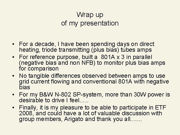
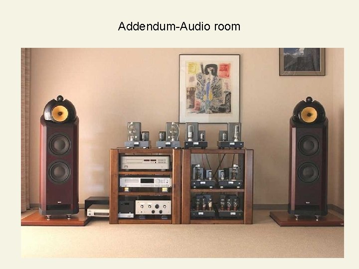
Wrap up of my presentation • For a decade, I have been spending days on direct heating, triode transmitting (plus bias) tubes amps • For reference purpose, built a 801 A x 3 in parallel (negative bias and non NFB) to monitor plus bias amps for comparison • No tangible differences observed between amps to use grid current flowing and conventional 801 A with negative bias • For my B&W N-802 SP-system, more than 30 W power is desirable to drive I feel…. . • Finally, it is my pleasure to be able to participate in ETF 2008, and could have a lot of valuable discussion with group members, Arigato and thank you all. . . .
Addendum-Audio room
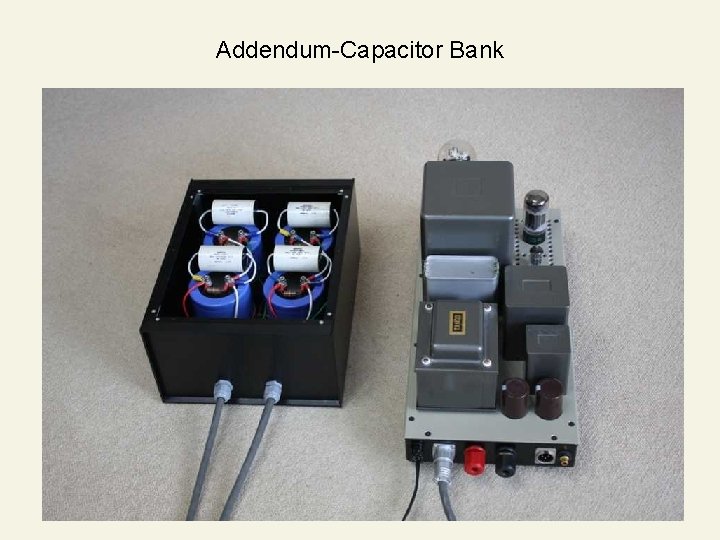
Addendum-Capacitor Bank
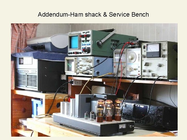
Addendum-Ham shack & Service Bench