
ELEN E 4810 Digital Signal Processing Topic 8
- Slides: 44
ELEN E 4810: Digital Signal Processing Topic 8: Filter Design: IIR 1. Filter Design Specifications 2. Analog Filter Design 3. Digital Filters from Analog Prototypes Dan Ellis 2003 -11 -06 1
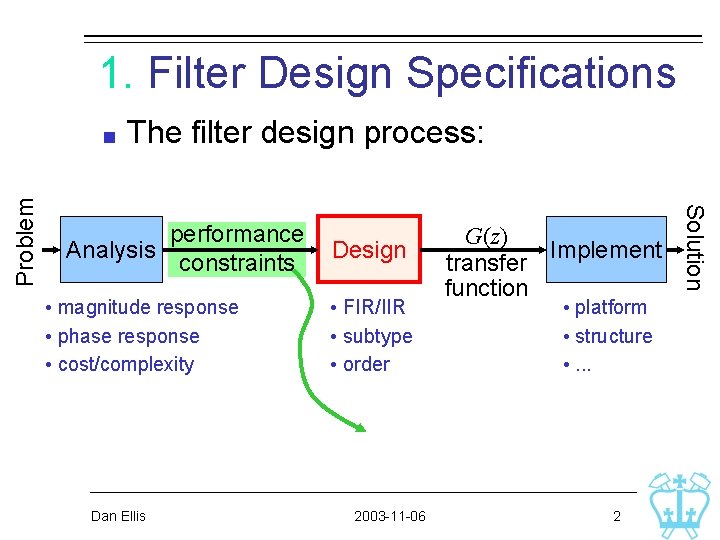
1. Filter Design Specifications The filter design process: performance Analysis constraints • magnitude response • phase response • cost/complexity Dan Ellis Design • FIR/IIR • subtype • order 2003 -11 -06 G(z) Implement transfer function • platform • structure • . . . 2 Solution Problem
Performance Constraints . . in terms of magnitude response: Dan Ellis 2003 -11 -06 3
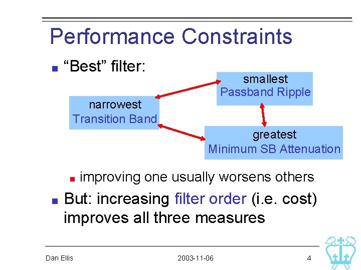
Performance Constraints “Best” filter: smallest Passband Ripple narrowest Transition Band greatest Minimum SB Attenuation improving one usually worsens others But: increasing filter order (i. e. cost) improves all three measures Dan Ellis 2003 -11 -06 4
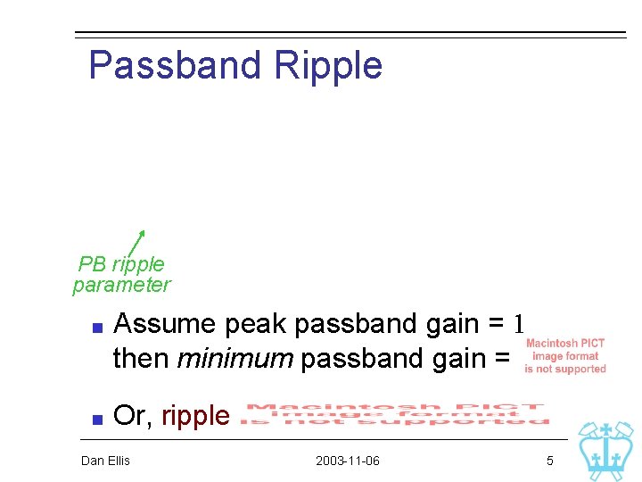
Passband Ripple PB ripple parameter Assume peak passband gain = 1 then minimum passband gain = Or, ripple Dan Ellis 2003 -11 -06 5
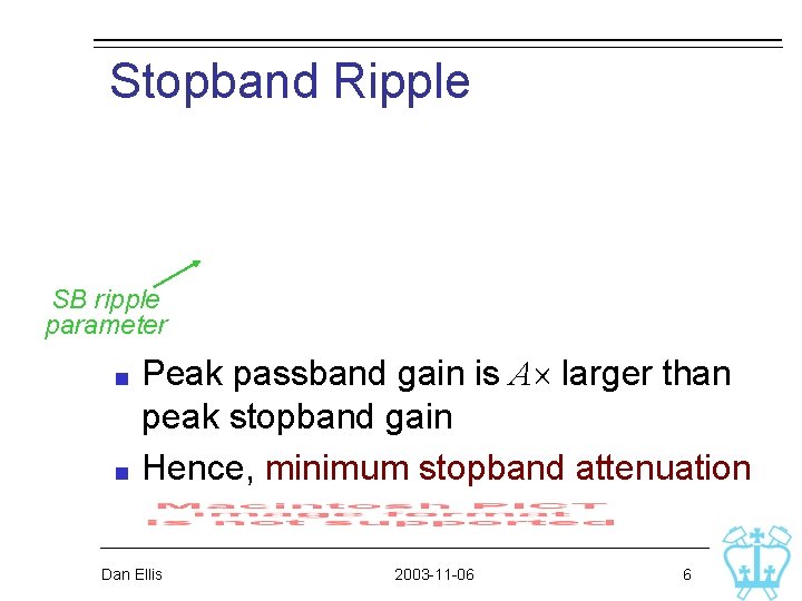
Stopband Ripple SB ripple parameter Peak passband gain is A larger than peak stopband gain Hence, minimum stopband attenuation Dan Ellis 2003 -11 -06 6
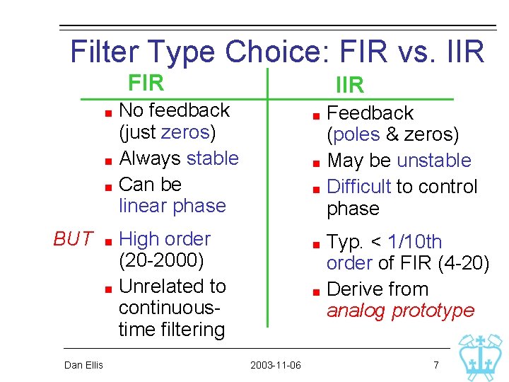
Filter Type Choice: FIR vs. IIR FIR IIR No feedback (just zeros) Always stable Can be linear phase Feedback (poles & zeros) May be unstable Difficult to control phase BUT High order (20 -2000) Unrelated to continuoustime filtering Typ. < 1/10 th order of FIR (4 -20) Derive from analog prototype Dan Ellis 2003 -11 -06 7
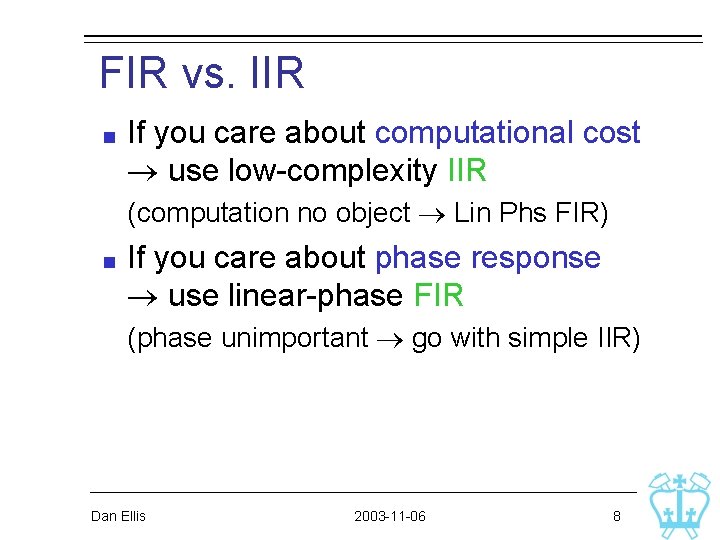
FIR vs. IIR If you care about computational cost use low-complexity IIR (computation no object Lin Phs FIR) If you care about phase response use linear-phase FIR (phase unimportant go with simple IIR) Dan Ellis 2003 -11 -06 8
IIR Filter Design IIR filters are directly related to analog filters (continuous time) via a mapping of H(s) (CT) to H(z) (DT) that preserves many properties Analog filter design is sophisticated signal processing research since 1940 s Design IIR filters via analog prototype hence, need to learn some CT filter design Dan Ellis 2003 -11 -06 9
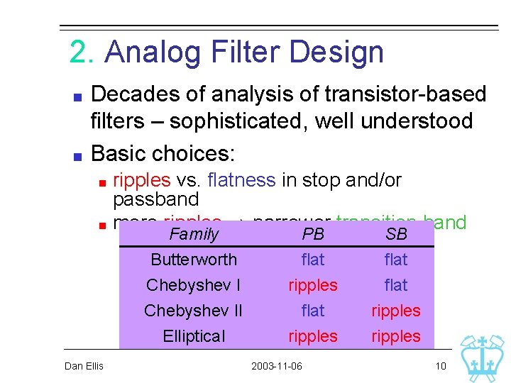
2. Analog Filter Design Decades of analysis of transistor-based filters – sophisticated, well understood Basic choices: ripples vs. flatness in stop and/or passband more ripples narrower transition band Dan Ellis Family Butterworth Chebyshev II PB flat ripples flat SB flat ripples Elliptical ripples 2003 -11 -06 10
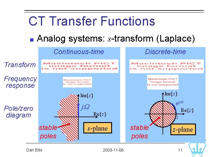
CT Transfer Functions Analog systems: s-transform (Laplace) Continuous-time Discrete-time Transform Frequency response Im{z} Im{s} e jw j. W Pole/zero diagram Re{z} Re{s} stable poles Dan Ellis s-plane 2003 -11 -06 1 stable poles z-plane 11
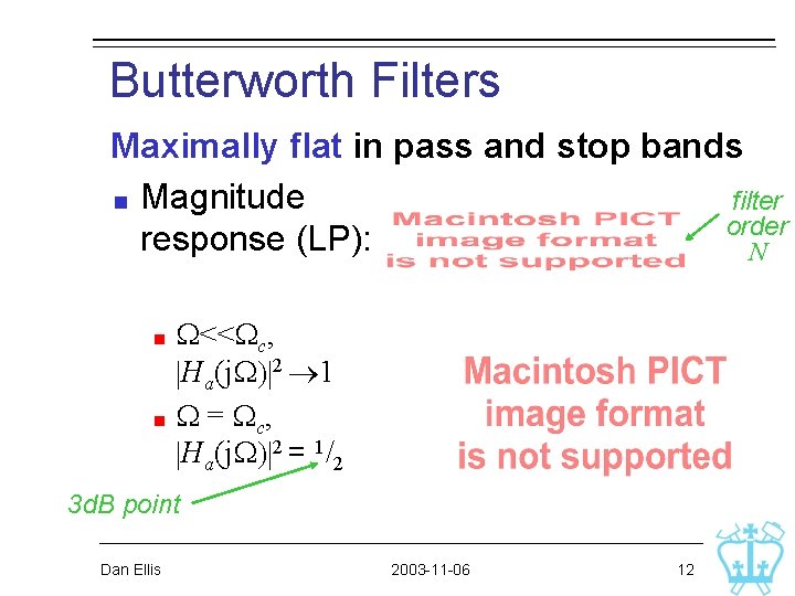
Butterworth Filters Maximally flat in pass and stop bands Magnitude filter order response (LP): N W<<Wc, |Ha(j. W)|2 1 W = Wc , |Ha(j. W)|2 = 1/2 3 d. B point Dan Ellis 2003 -11 -06 12
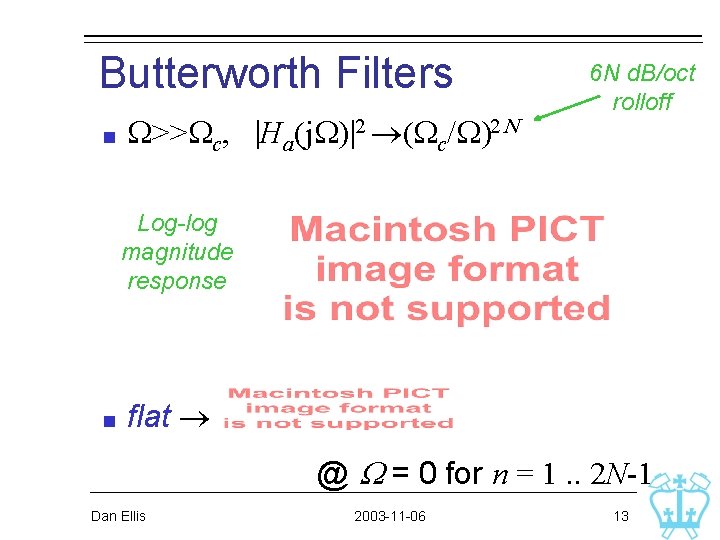
Butterworth Filters W>>Wc, |Ha(j. W)|2 (Wc/W)2 N 6 N d. B/oct rolloff Log-log magnitude response flat @ W = 0 for n = 1. . 2 N-1 Dan Ellis 2003 -11 -06 13
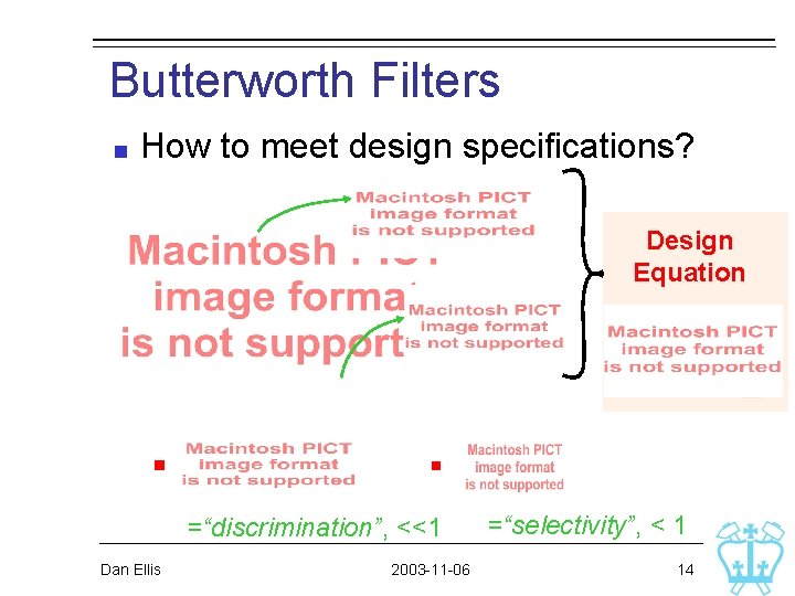
Butterworth Filters How to meet design specifications? Design Equation =“discrimination”, <<1 Dan Ellis 2003 -11 -06 =“selectivity”, < 1 14
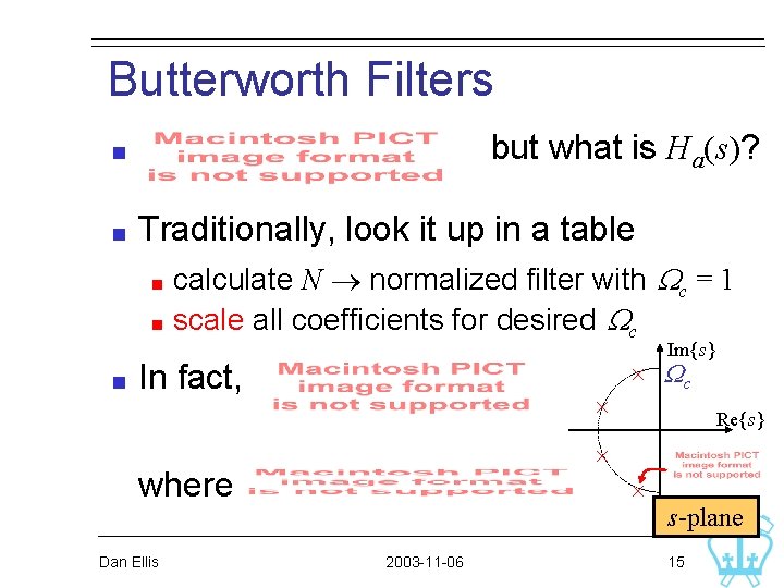
Butterworth Filters but what is Ha(s)? Traditionally, look it up in a table calculate N normalized filter with Wc = 1 scale all coefficients for desired Wc Im{s} In fact, Re{s} where Dan Ellis Wc 2003 -11 -06 s-plane 15
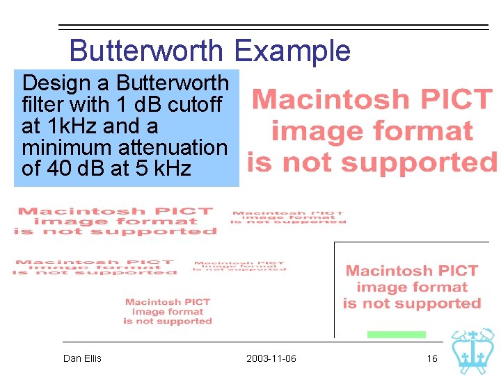
Butterworth Example Design a Butterworth filter with 1 d. B cutoff at 1 k. Hz and a minimum attenuation of 40 d. B at 5 k. Hz Dan Ellis 2003 -11 -06 16
Butterworth Example Order N = 4 will satisfy constraints; What are Wc and filter coefficients? from a table, W-1 d. B = 0. 845 when Wc = 1000/0. 845 = 1. 184 k. Hz from a table, get normalized coefficients for N = 4, scale by 1184 Or, use Matlab: [b, a] = butter(N, Wc, ’s’); Dan Ellis 2003 -11 -06 17 M
Chebyshev I Filter Equiripple in passband (flat in stopband) minimize maximum error Chebyshev polynomial of order N Dan Ellis 2003 -11 -06 18
Chebyshev I Filter Design procedure: desired passband ripple e min. stopband atten. , Wp, Ws N : 1/k 1, discrimination 1/k, selectivity Dan Ellis 2003 -11 -06 19
Chebyshev I Filter What is Ha(s)? complicated, get from a table . . or from Matlab cheby 1(N, r, Wp, ’s’) all-pole; can inspect them: . . like squashed-in Butterworth Dan Ellis 2003 -11 -06 20
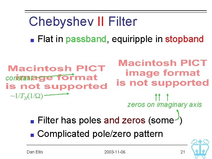
Chebyshev II Filter Flat in passband, equiripple in stopband constant ~1/TN(1/W) zeros on imaginary axis Filter has poles and zeros (some ) Complicated pole/zero pattern Dan Ellis 2003 -11 -06 21
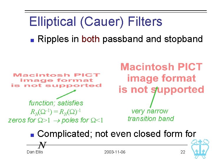
Elliptical (Cauer) Filters Ripples in both passband stopband function; satisfies RN(W-1) = RN(W)-1 zeros for W>1 poles for W<1 very narrow transition band Complicated; not even closed form for N Dan Ellis 2003 -11 -06 22
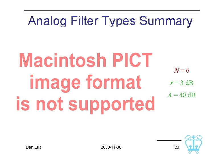
Analog Filter Types Summary N=6 r = 3 d. B A = 40 d. B Dan Ellis 2003 -11 -06 23
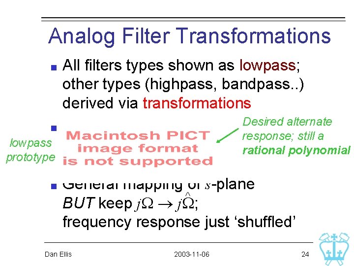
Analog Filter Transformations All filters types shown as lowpass; other types (highpass, bandpass. . ) derived via transformations Desired alternate i. e. response; still a rational polynomial lowpass prototype General mapping of s-plane ^ BUT keep j. W; frequency response just ‘shuffled’ Dan Ellis 2003 -11 -06 24
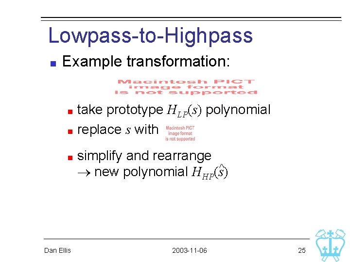
Lowpass-to-Highpass Example transformation: take prototype HLP(s) polynomial replace s with Dan Ellis simplify and rearrange ^ new polynomial HHP(s) 2003 -11 -06 25
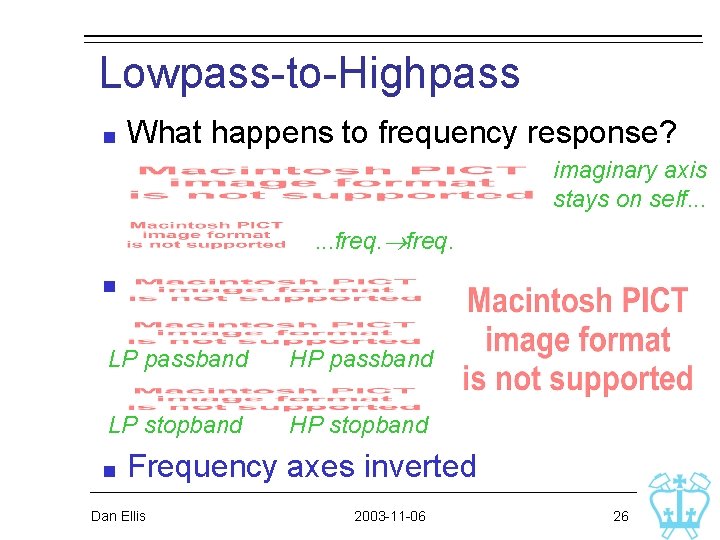
Lowpass-to-Highpass What happens to frequency response? imaginary axis stays on self. . . freq. LP passband HP passband LP stopband HP stopband Frequency axes inverted Dan Ellis 2003 -11 -06 26
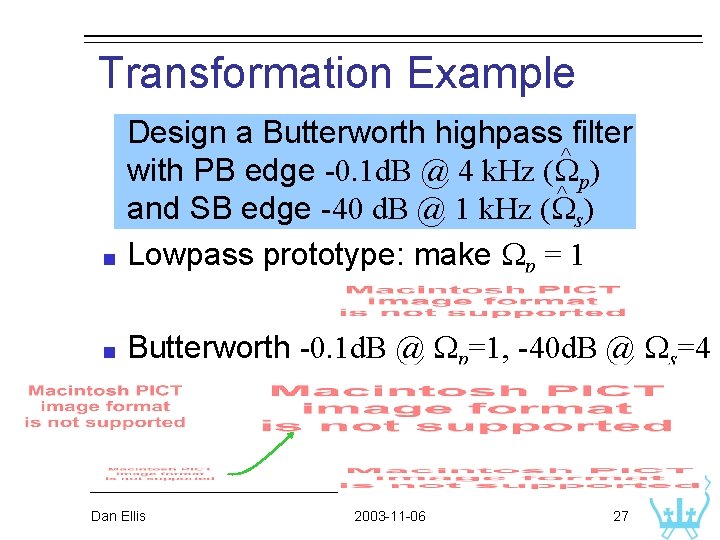
Transformation Example Design a Butterworth highpass filter ^ with PB edge -0. 1 d. B @ 4 k. Hz (Wp) ^ and SB edge -40 d. B @ 1 k. Hz (Ws) Lowpass prototype: make Wp = 1 Butterworth -0. 1 d. B @ Wp=1, -40 d. B @ Ws=4 Dan Ellis 2003 -11 -06 27
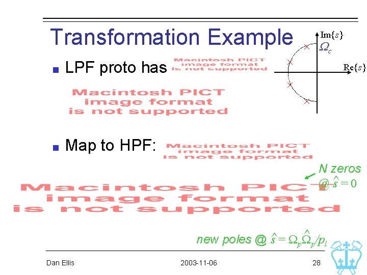
Transformation Example LPF proto has Im{s} Wc Re{s} Map to HPF: N zeros @ ^s = 0 ^ /p new poles @ s^ = Wp. W p l Dan Ellis 2003 -11 -06 28
Transformation Example In Matlab: Wp Ws R p [N, Wc]=buttord(1, 4, 0. 1, 40, 's'); [B, A] = butter(N, Wc, 's'); [n, d] = lp 2 hp(B, A, 2*pi*4000); Dan Ellis 2003 -11 -06 Rs 29
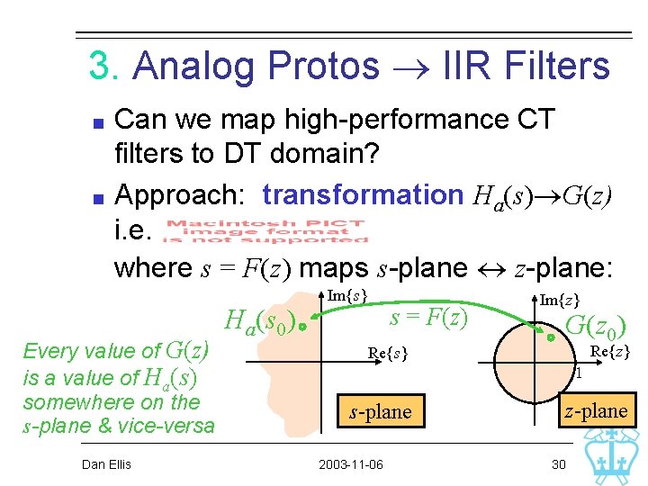
3. Analog Protos IIR Filters Can we map high-performance CT filters to DT domain? Approach: transformation Ha(s) G(z) i. e. where s = F(z) maps s-plane z-plane: Every value of G(z) is a value of Ha(s) somewhere on the s-plane & vice-versa Dan Ellis Ha(s 0) Im{s} s = F(z) Re{s} Im{z} G(z 0) Re{z} 1 s-plane 2003 -11 -06 z-plane 30
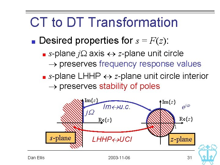
CT to DT Transformation Desired properties for s = F(z): s-plane j. W axis z-plane unit circle preserves frequency response values s-plane LHHP z-plane unit circle interior preserves stability of poles Im{s} j. W Im u. c. Re{s} s-plane Dan Ellis LHHP UCI 2003 -11 -06 Im{z} e jw Re{z} 1 z-plane 31
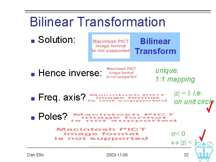
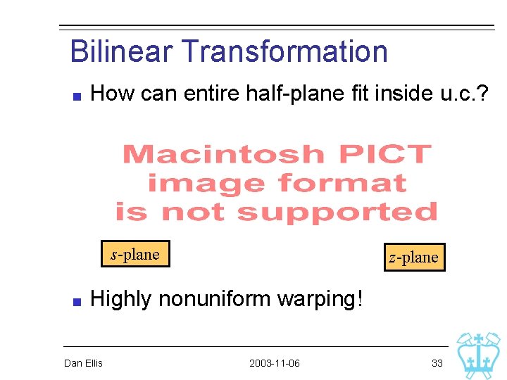
Bilinear Transformation Solution: Hence inverse: Freq. axis? Poles? Bilinear Transform unique, 1: 1 mapping |z| = 1 i. e. on unit circle s< 0 |z| < 1 Dan Ellis 2003 -11 -06 32
Bilinear Transformation How can entire half-plane fit inside u. c. ? s-plane z-plane Highly nonuniform warping! Dan Ellis 2003 -11 -06 33
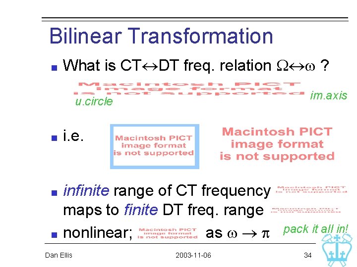
Bilinear Transformation What is CT DT freq. relation W w ? im. axis u. circle i. e. infinite range of CT frequency maps to finite DT freq. range nonlinear; as w p Dan Ellis 2003 -11 -06 pack it all in! 34
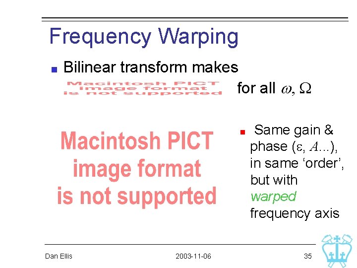
Frequency Warping Bilinear transform makes for all w, W Dan Ellis 2003 -11 -06 Same gain & phase (e, A. . . ), in same ‘order’, but with warped frequency axis 35
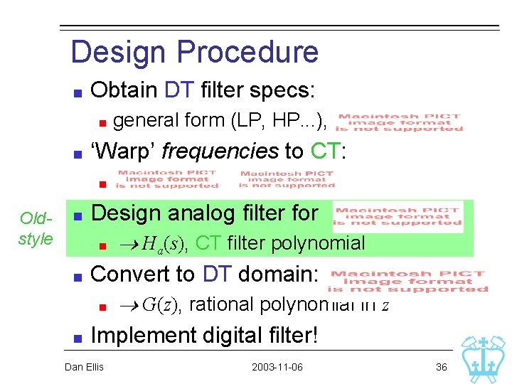
Design Procedure Obtain DT filter specs: general form (LP, HP. . . ), ‘Warp’ frequencies to CT: Oldstyle Design analog filter for Convert to DT domain: Ha(s), CT filter polynomial G(z), rational polynomial in z Implement digital filter! Dan Ellis 2003 -11 -06 36
Bilinear Transform Example DT domain requirements: Lowpass, 1 d. B ripple in PB, wp = 0. 4 p, SB attenuation ≥ 40 d. B @ ws = 0. 5 p, attenuation increases with frequency SB ripples, PB monotonic Chebyshev I Dan Ellis 2003 -11 -06 37
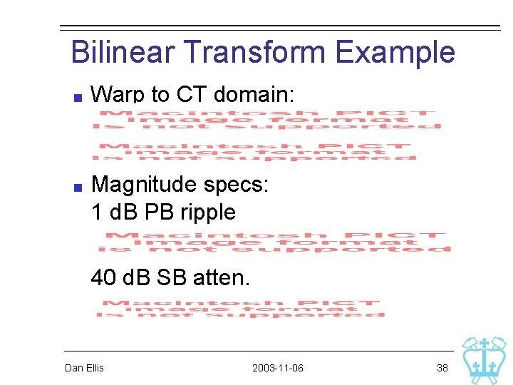
Bilinear Transform Example Warp to CT domain: Magnitude specs: 1 d. B PB ripple 40 d. B SB atten. Dan Ellis 2003 -11 -06 38
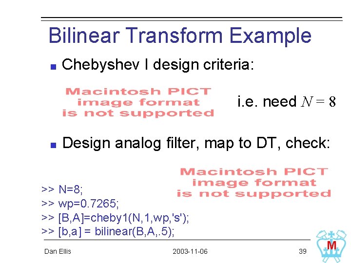
Bilinear Transform Example Chebyshev I design criteria: i. e. need N = 8 Design analog filter, map to DT, check: >> N=8; >> wp=0. 7265; >> [B, A]=cheby 1(N, 1, wp, 's'); >> [b, a] = bilinear(B, A, . 5); Dan Ellis 2003 -11 -06 39 M
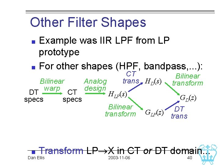
Other Filter Shapes Example was IIR LPF from LP prototype For other shapes (HPF, bandpass, . . . ): Bilinear warp DT specs CT specs Analog design CT trans HD(s) HLP(s) Bilinear transform GD(z) GLP(z) DT trans Transform LP X in CT or DT domain. . . Dan Ellis 2003 -11 -06 40
DT Spectral Transformations Same idea as CT LPF HPF mapping, but in z-domain: To behave well, should: map u. c. (preserve G(ejw) values) map u. c. interior (stability) i. e. Dan Ellis in fact, matches the definition of an allpass filter. . . replace delays with 2003 -11 -06 41
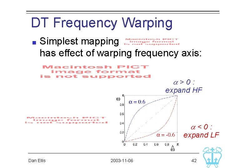
DT Frequency Warping Simplest mapping has effect of warping frequency axis: a>0: expand HF a<0: expand LF Dan Ellis 2003 -11 -06 42
Another Design Example Spec: Bandpass, from 800 -1600 Hz (SR = 8 k. Hz) Ripple = 1 d. B, min. stopband atten. = 60 d. B 8 th order, best transition band Use elliptical for best performance Full design path: design analog LPF prototype analog LPF BPF CT BPF DT BPF (Bilinear) Dan Ellis 2003 -11 -06 43
Another Design Example Or, do it all in one step in Matlab: [b, a] = ellip(8, 1, 60, [800 1600]/(8000/2)); Dan Ellis 2003 -11 -06 44