
Electronics Trigger and DAQ Attivit TDR Studio dei

- Slides: 19
Electronics Trigger and DAQ
Attività TDR • Studio dei canali ottici di trasmissione. Sezione di Napoli. • Studio del sistema di lettura dati dal FE (ROM readout module): funzione di interfaccia del FEE alla farm HLT. Sezioni di Bologna e Padova. • Trigger hardware (L 1). Sezioni di Roma 1, Roma 3 e Napoli.
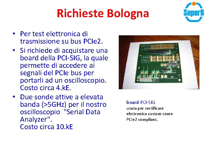
Richieste Bologna • Per test elettronica di trasmissione su bus PCIe 2. • Si richiede di acquistare una board della PCI-SIG, la quale permette di accedere ai segnali del PCIe bus per portarli ad un oscilloscopio. Costo circa 4. k. E. • Due sonde attive a elevata banda (>5 GHz) per il nostro oscilloscopio "Serial Data Analyzer". Costo circa 10. k. E board PCI-SIG usata per certificare elettronica custom come PCIe 2 compliant.
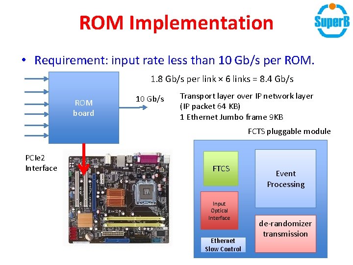
ROM Implementation • Requirement: input rate less than 10 Gb/s per ROM. 1. 8 Gb/s per link × 6 links = 8. 4 Gb/s ROM board 10 Gb/s Transport layer over IP network layer (IP packet 64 KB) 1 Ethernet Jumbo frame 9 KB FCTS pluggable module PCIe 2 Interface FTCS Input Optical Interface Ethernet Slow Control Event Processing de-randomizer transmission
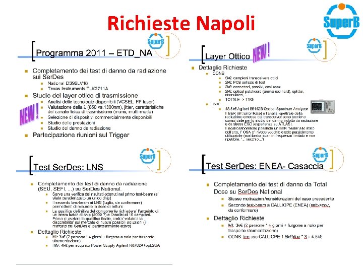
Richieste Napoli
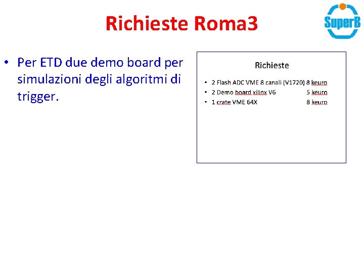
Richieste Roma 3 • Per ETD due demo board per simulazioni degli algoritmi di trigger.
Trigger Rates and Event Sizes • Estimates extrapolated from Ba. Bar for a detector with Ba. Barlike acceptance. • Level-1 trigger rates. – At L=1036 cm-2 s-1: 50 k. Hz Bhabha, 25 k. Hz beam backgrounds, 25 k. Hz “irreducible” (physics + backgrounds). - 50% headroom desirable (from Ba. Bar experience) for efficient operation. – Baseline 150 k. Hz Level-1 -accept rate capability. • Event size: 100 k. Byte • Pre-ROM sizes is about 500 k. Byte. • High-Level Trigger and Logging – Expect to be able to achieve 25 nb logging cross section with a safe real-time high-level trigger, corresponding to: 25 k. Hz x 100 k. B = 2. Gb/s – Logging cross section could be improved by 5÷ 10 nb by using a more tighter filter in the HLT (there is a cost vs. risk tradeoff). 7
Design Principles • Apply lessons learned from Ba. Bar and LHC experiments. • Synchronous design • No “untriggered” readouts – Except for trigger data streams. • Use off-the-shelf components where applicable. – Links, networks, computers, other components. – Software (what can we reuse from other experiments). • Modularize the design across the system – Common building blocks and modules for common functions – Implement sub-detector specific functions on specific modules – Carriers, daughter boards, mezzanines • Design the FEE with radiation-hardness constraint in mind. • Design for high-efficiency and high-reliability. – Design for minimal intrinsic dead time: current goal being 1%. – Automate. Minimize manual intervention. Minimize physical hardware access requirements. 8
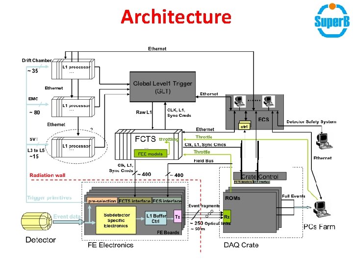
Synchronous, Pipelined, Fixed-Latency Design • Front-end electronics, Fast Control and Timing System and Trigger synchronized to the global clock. • Analog signals sampled with global clock (or multiples of global clock). Samples shifted into latency buffers (fixed depth). • Synchronous reduced-data streams derived from some sub-detectors (DCH, EMC, …) and sent to the Level-1 trigger processors. • Pipelined Level-1 trigger generates a trigger decision after a fixed latency synchronous to global clock. • In case of an L 1 -accept the readout command is sent to the FCTS and broadcast to the Front-end electronics (over synchronous, fixed-latency links). • Front-end electronics transfer data of the corresponding readout window to the de-randomizer buffers for data transmission. • Data from de-randomizer buffers are sent over optical links (no fixed latency requirement here) to the Readout Modules (ROMs). • Every ROMs in case applies zero suppression / feature extraction and combines event fragments from all its links. • Resulting partially event-built fragments are then sent via the network event builder into the HLT farm. 9
Architecture
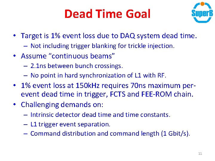
Dead Time Goal • Target is 1% event loss due to DAQ system dead time. – Not including trigger blanking for trickle injection. • Assume “continuous beams” – 2. 1 ns between bunch crossings. – No point in hard synchronization of L 1 with RF. • 1% event loss at 150 k. Hz requires 70 ns maximum perevent dead time in trigger, FCTS and FEE-ROM chain. • Challenging demands on: – Intrinsic detector dead time and time constants. – L 1 trigger event separation. – Command distribution and command length (1 Gbit/s). 11
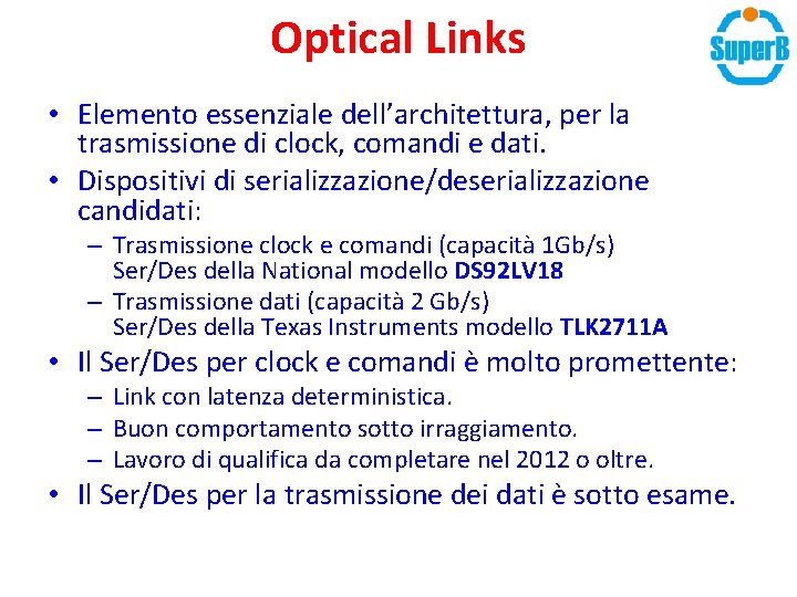
Optical Links • Elemento essenziale dell’architettura, per la trasmissione di clock, comandi e dati. • Dispositivi di serializzazione/deserializzazione candidati: – Trasmissione clock e comandi (capacità 1 Gb/s) Ser/Des della National modello DS 92 LV 18 – Trasmissione dati (capacità 2 Gb/s) Ser/Des della Texas Instruments modello TLK 2711 A • Il Ser/Des per clock e comandi è molto promettente: – Link con latenza deterministica. – Buon comportamento sotto irraggiamento. – Lavoro di qualifica da completare nel 2012 o oltre. • Il Ser/Des per la trasmissione dei dati è sotto esame.
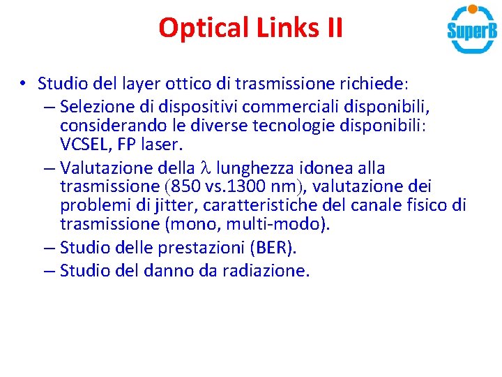
Optical Links II • Studio del layer ottico di trasmissione richiede: – Selezione di dispositivi commerciali disponibili, considerando le diverse tecnologie disponibili: VCSEL, FP laser. – Valutazione della l lunghezza idonea alla trasmissione (850 vs. 1300 nm), valutazione dei problemi di jitter, caratteristiche del canale fisico di trasmissione (mono, multi-modo). – Studio delle prestazioni (BER). – Studio del danno da radiazione.
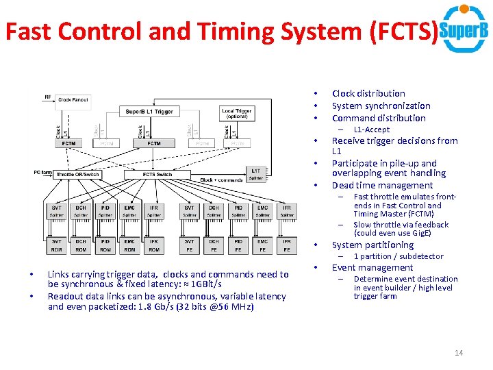
Fast Control and Timing System (FCTS) • • • Clock distribution System synchronization Command distribution – • • • Receive trigger decisions from L 1 Participate in pile-up and overlapping event handling Dead time management – – • • Links carrying trigger data, clocks and commands need to be synchronous & fixed latency: ≈ 1 GBit/s Readout data links can be asynchronous, variable latency and even packetized: 1. 8 Gb/s (32 bits @56 MHz) • Fast throttle emulates frontends in Fast Control and Timing Master (FCTM) Slow throttle via feedback (could even use Gig. E) System partitioning – • L 1 -Accept 1 partition / subdetector Event management – Determine event destination in event builder / high level trigger farm 14
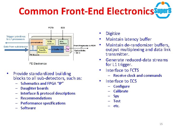
Common Front-End Electronics • Provide standardized building blocks to all sub-detectors, such as: – – – Schematics and FPGA “IP” Daughter boards Interface & protocol descriptions Recommendations Performance specifications Software • Digitize • Maintain latency buffer • Maintain de-randomizer buffers, output multiplexing and data link transmitter. • Generate reduced-data streams for L 1 trigger. • Interface to FCTS – Receive clock and commands • Interface to ECS – – – Configure Calibrate Spy Test etc. 15
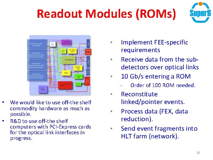
Readout Modules (ROMs) • • • Implement FEE-specific requirements Receive data from the subdetectors over optical links 10 Gb/s entering a ROM – • • We would like to use off-the shelf commodity hardware as much as possible. • R&D to use off-the shelf computers with PCI-Express cards for the optical link interfaces in progress. • • Order of 100 ROM needed. Reconstitute linked/pointer events. Process data (FEX, data reduction). Send event fragments into HLT farm (network). 16
Event Builder and Network • Combines event fragments from ROMs into complete events in the HLT farm. • Prefer the fragment routing to be determined by FCTS • FCTS decides to which HLT node all fragments of a given events are sent (enforces global synchronization), distribute as node number via FCTS – Event-to-event decisions taken by FCTS firmware (using table of node numbers) – Node availability / capacity communicated to FCTS via a slow feedback protocol (over network in software) • Choice of network technology – Combination of 10 Gbit/s and 1 GBit/s Ethernet prime candidate – UDP vs. TCP … a long contentious issue: pros and cons to both. – Can we use DCB/Converged Ethernet for layer-2 end-to-end flow control in the EB network? 17
High-Level Trigger Farm and Logging • Standard off-the shelf rack-mount servers. • Receivers in the network event builder: receive event fragments from ROMs, build complete events. • HLT trigger (Level-3) – Fast tracking (using L 1 info as seeds), fast clustering. – 10 ms/event is baseline assumption, 5 -10 x what the Ba. Bar L 3 needed on 2005 vintage CPUs, plenty of headroom. – 1500 CPU cores needed on contemporary hardware: ~150 servers 16 cores, 10 usable for HLT purposes. • Data logging & buffering Few TByte/node. Local disk (e. g. RAID 1 as in Ba. Bar)? – or - Storage servers accessed via a back-end network? Probably 2 days’ worth of local storage (2 TByte/node)? Depends on SLD/SLA for data archive facility. – No file aggregation into “runs” bookkeeping – Back-end network to archive facility – – 18
Data Quality Monitoring, Control Systems • Data Quality Monitoring – – Same concepts as in Ba. Bar: Collect histograms from HLT Collect data from ETD monitoring Run fast and/or full reconstruction on sub-sample of events and collect histograms • May include specialized reconstruction for e. g. beam spot position monitoring – Could run on same machines as HLT processes (in virtual machines? ) or a separate small farm (“event server clients”) – Present to operator via GUI – Automated histogram comparison with reference histograms and alerting • Control Systems – Run Control • Coherent management of the ETD and Online systems – User interface, managing system-wide configuration, reporting, error handling, start and stop data taking – Detector Control / Slow Control • Monitor and control detector and detector environment – Maximize automation across these systems • Goal: 2 -person shifts like in Ba. Bar • “auto-pilot” mode where detector operations is controlled by the machine • Automatic error detection and recovery where possible – Assume we can benefit from systems developed for the LHC, the Super. B accelerator control system and commercial systems 19