electronics fundamentals circuits devices and applications THOMAS L


 of a coil")

 The unit of inductance. RL time A")


- Slides: 40
electronics fundamentals circuits, devices, and applications THOMAS L. FLOYD DAVID M. BUCHLA ขดลวดเหนยวน ำ Electronics Fundamentals 8 th edition Floyd/Buchla © 2010 Pearson Education, Upper Saddle River, NJ 07458. All Rights Reserved.
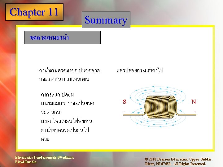
Chapter 11 1 Summary Faraday’s law was introduced in Chapter 7 and repeated here because of its importance to inductors. The amount of voltage induced in a coil is directly proportional to the rate of change of the magnetic field with respect to the coil. Electronics Fundamentals 8 th edition Floyd/Buchla © 2010 Pearson Education, Upper Saddle River, NJ 07458. All Rights Reserved.
Chapter 11 1 Summary Lenz’s law was also introduced in Chapter 7 and is an extension of Faraday’s law, defining the direction of the induced voltage: When the current through a coil changes and an induced voltage is created as a result of the changing magnetic field, the direction of the induced voltage is such that it always opposes the change in the current. Electronics Fundamentals 8 th edition Floyd/Buchla © 2010 Pearson Education, Upper Saddle River, NJ 07458. All Rights Reserved.
Chapter 11 1 Summary Lenz’s law A basic circuit to demonstrate Lenz’s law is shown. Initially, the SW is open and there is a small current in the circuit through L and R 1. Electronics Fundamentals 8 th edition Floyd/Buchla © 2010 Pearson Education, Upper Saddle River, NJ 07458. All Rights Reserved.
Chapter 11 1 Summary Lenz’s law SW closes and immediately a voltage appears across L that tends to oppose any change in current. Initially, the meter reads same current as before the switch was closed. Electronics Fundamentals 8 th edition Floyd/Buchla © 2010 Pearson Education, Upper Saddle River, NJ 07458. All Rights Reserved.
Chapter 11 1 Summary Lenz’s law After a time, the current stabilizes at a higher level (due to I 2) as the voltage decays across the coil. Later, the meter reads a higher current because of the load change. Electronics Fundamentals 8 th edition Floyd/Buchla © 2010 Pearson Education, Upper Saddle River, NJ 07458. All Rights Reserved.
Chapter 11 1 Summary Practical inductors In addition to inductance, actual inductors have winding resistance (RW) due to the resistance of the wire and winding capacitance (CW) between turns. An equivalent circuit for a practical inductor including these effects is shown: Notice that the winding resistance is in series with the coil and the winding capacitance is in parallel with both. Electronics Fundamentals 8 th edition Floyd/Buchla © 2010 Pearson Education, Upper Saddle River, NJ 07458. All Rights Reserved.
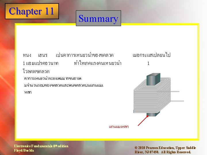
Chapter 11 1 Summary Factors affecting inductance Four factors affect the amount of inductance for a coil. The equation for the inductance of a coil is where L = inductance in henries N = number of turns of wire m = permeability in H/m (same as Wb/At-m) l = coil length on meters Electronics Fundamentals 8 th edition Floyd/Buchla © 2010 Pearson Education, Upper Saddle River, NJ 07458. All Rights Reserved.
Chapter 11 1 Summary What is the inductance of a 2 cm long, 150 turn coil wrapped on an low carbon steel core that is 0. 5 cm diameter? The permeability of low carbon steel is 2. 5 x 10 -4 H/m (Wb/At-m). 22 m. H Electronics Fundamentals 8 th edition Floyd/Buchla © 2010 Pearson Education, Upper Saddle River, NJ 07458. All Rights Reserved.
Chapter 11 1 Summary ขดลวดเหนยวนำทใ ชงาน Electronics Fundamentals 8 th edition Floyd/Buchla © 2010 Pearson Education, Upper Saddle River, NJ 07458. All Rights Reserved.
Chapter 11 1 Summary ตวเหนยวนำอนกร ม ถาตอขดลวด 1. 5 m. H อนกรมกบ 680 m. H จงหาคาการเหนยวนำรวม 2. 18 m. H Electronics Fundamentals 8 th edition Floyd/Buchla © 2010 Pearson Education, Upper Saddle River, NJ 07458. All Rights Reserved.
Chapter 11 1 Summary ตวเหนยวนำขนาน ตวเหนยวนำสองตวตอขนานกน Electronics Fundamentals 8 th edition Floyd/Buchla © 2010 Pearson Education, Upper Saddle River, NJ 07458. All Rights Reserved.
Chapter 11 1 Summary ตวเหนยวนำขนาน ตวเหนยวนำ 1. 5 m. H ตอขนานกบตวเหนยวนำ 680 m. H จงหาคาความเหนยวนำรวม 468 m. H Electronics Fundamentals 8 th edition Floyd/Buchla © 2010 Pearson Education, Upper Saddle River, NJ 07458. All Rights Reserved.
Chapter 11 1 Summary ถาตอแหลงจายเปนสญญาณส เหลยม จะไดกราฟดงรป VS VL VR Electronics Fundamentals 8 th edition Floyd/Buchla © 2010 Pearson Education, Upper Saddle River, NJ 07458. All Rights Reserved.
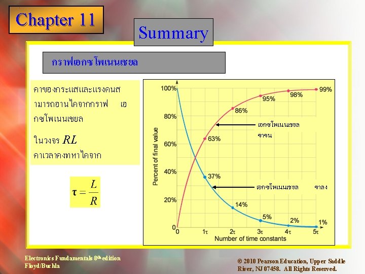
Chapter 11 1 Summary ในวงจรอนกรม RL เมอไรท VR > 2 VL อานคา เอกซโพเนนเช ยล ขาขนทระดบ หลงจาก 1. 1 67% t Electronics Fundamentals 8 th edition Floyd/Buchla © 2010 Pearson Education, Upper Saddle River, NJ 07458. All Rights Reserved.
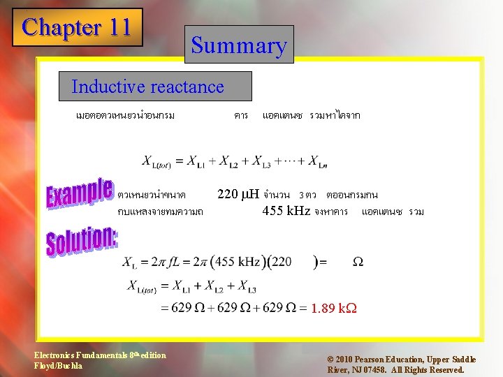
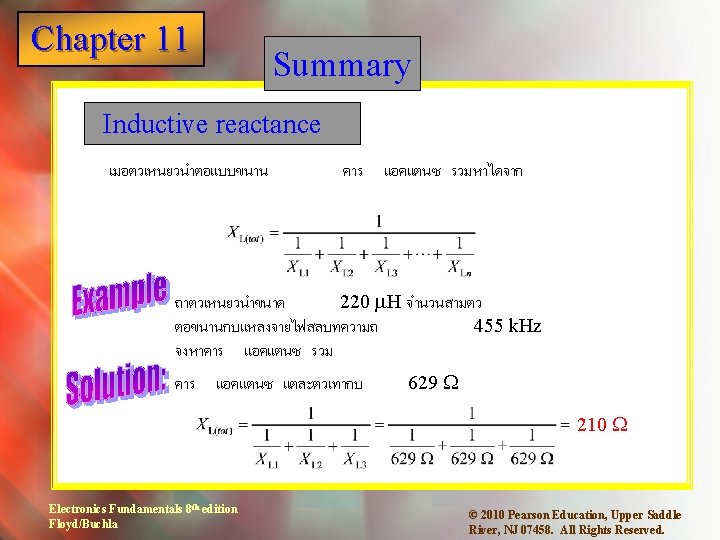
Chapter 11 1 Summary Inductive reactance เปนคาทตอตานไฟ ac ของตวเหนยวนำ หาไดจาก จงหาคาร ทความถ Electronics Fundamentals 8 th edition Floyd/Buchla แอคแตนซ ของตวเหนยวนำ 550 k. Hz 33 m. H 114 W © 2010 Pearson Education, Upper Saddle River, NJ 07458. All Rights Reserved.
Chapter 11 1 Summary Inductive phase shift เมอจายไซน เวฟเขาไ ปในตวเหนยวนำ จะเกดการเลอนเฟสระห วางแรงดนและกระแส โดยแรงดนจะนำกระแส 90 o. Electronics Fundamentals 8 th edition Floyd/Buchla © 2010 Pearson Education, Upper Saddle River, NJ 07458. All Rights Reserved.
Chapter 11 1 Power in an inductor True Power: Ideally, inductors do not dissipate power. However, a small amount of power is dissipated in winding resistance given by the equation: Ptrue = (Irms)2 RW Reactive Power: Reactive power is a measure of the rate at which the inductor stores and returns energy. One form of the reactive power equation is: Pr=Vrms. Irms The unit for reactive power is the VAR. Electronics Fundamentals 8 th edition Floyd/Buchla © 2010 Pearson Education, Upper Saddle River, NJ 07458. All Rights Reserved.
Chapter 11 1 Q of a coil The quality factor (Q) of a coil is given by the ratio of reactive power to true power. For a series circuit, I cancels, leaving Electronics Fundamentals 8 th edition Floyd/Buchla © 2010 Pearson Education, Upper Saddle River, NJ 07458. All Rights Reserved.
Chapter 11 1 Key Terms Inductor An electrical device formed by a wire wound around a core having the property of inductance; also known as a coil. Winding The loops or turns of wire in an inductor. Induced Voltage produced as a result of a changing voltage magnetic field. Inductance The property of an inductor whereby a change in current causes the inductor to produce a voltage that opposes the change in current. Electronics Fundamentals 8 th edition Floyd/Buchla © 2010 Pearson Education, Upper Saddle River, NJ 07458. All Rights Reserved.
Chapter 11 1 Key Terms Henry (H) The unit of inductance. RL time A fixed time interval set by the L and R constant values, that determines the time response of a circuit. It equals the ratio of L/R. Inductive The opposition of an inductor to sinusoidal reactance current. The unit is the ohm. Quality factor The ratio of reactive power to true power for an inductor. Electronics Fundamentals 8 th edition Floyd/Buchla © 2010 Pearson Education, Upper Saddle River, NJ 07458. All Rights Reserved.
Chapter 11 1 Quiz 1. Assuming all other factors are the same, the inductance of an inductor will be larger if a. more turns are added b. the area is made larger c. the length is shorter d. all of the above Electronics Fundamentals 8 th edition Floyd/Buchla © 2010 Pearson Education, Upper Saddle River, NJ 07458. All Rights Reserved.
Chapter 11 1 Quiz 2. The henry is defined as the inductance of a coil when a. a constant current of one amp develops one volt. b. one volt is induced due to a change in current of one amp per second. c. one amp is induced due to a change in voltage of one volt. d. the opposition to current is one ohm. Electronics Fundamentals 8 th edition Floyd/Buchla © 2010 Pearson Education, Upper Saddle River, NJ 07458. All Rights Reserved.
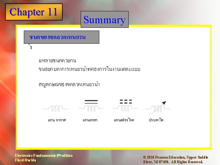
Chapter 11 1 Quiz 3. The symbol for a ferrite core inductor is a. b. c. d. Electronics Fundamentals 8 th edition Floyd/Buchla © 2010 Pearson Education, Upper Saddle River, NJ 07458. All Rights Reserved.
Chapter 11 1 Quiz 4. The symbol for a variable inductor is a. b. c. d. Electronics Fundamentals 8 th edition Floyd/Buchla © 2010 Pearson Education, Upper Saddle River, NJ 07458. All Rights Reserved.
Chapter 11 1 Quiz 5. The total inductance of a 270 m. H inductor connected in series with a 1. 2 m. H inductor is a. 220 m. H b. 271 m. H c. 599 m. H d. 1. 47 m. H Electronics Fundamentals 8 th edition Floyd/Buchla © 2010 Pearson Education, Upper Saddle River, NJ 07458. All Rights Reserved.
Chapter 11 1 Quiz 6. The total inductance of a 270 m. H inductor connected in parallel with a 1. 2 m. H inductor is a. 220 m. H b. 271 m. H c. 599 m. H d. 1. 47 m. H Electronics Fundamentals 8 th edition Floyd/Buchla © 2010 Pearson Education, Upper Saddle River, NJ 07458. All Rights Reserved.
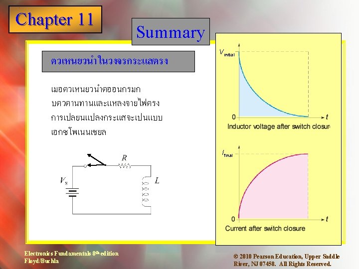
Chapter 11 1 Quiz 7. When an inductor is connected through a series resistor and switch to a dc voltage source, the voltage across the resistor after the switch closes has the shape of a. a straight line b. a rising exponential c. a falling exponential d. none of the above Electronics Fundamentals 8 th edition Floyd/Buchla © 2010 Pearson Education, Upper Saddle River, NJ 07458. All Rights Reserved.
Chapter 11 1 Quiz 8. For circuit shown, the time constant is a. 270 ns b. 270 ms c. 270 ms d. 3. 70 s Electronics Fundamentals 8 th edition Floyd/Buchla © 2010 Pearson Education, Upper Saddle River, NJ 07458. All Rights Reserved.
Chapter 11 1 Quiz 9. For circuit shown, assume the period of the square wave is 10 times longer than the time constant. The shape of the voltage across L is a. b. c. d. Electronics Fundamentals 8 th edition Floyd/Buchla © 2010 Pearson Education, Upper Saddle River, NJ 07458. All Rights Reserved.
Chapter 11 1 Quiz 10. If a sine wave from a function generator is applied to an inductor, the current will a. lag voltage by 90 o b. lag voltage by 45 o c. be in phase with the voltage d. none of the above Electronics Fundamentals 8 th edition Floyd/Buchla © 2010 Pearson Education, Upper Saddle River, NJ 07458. All Rights Reserved.
Chapter 11 1 Quiz Answers: Electronics Fundamentals 8 th edition Floyd/Buchla 1. d 6. a 2. b 7. b 3. d 8. a 4. c 9. c 5. d 10. a © 2010 Pearson Education, Upper Saddle River, NJ 07458. All Rights Reserved.