electronics fundamentals circuits devices and applications THOMAS L


 Forward")


- Slides: 35
electronics fundamentals circuits, devices, and applications THOMAS L. FLOYD DAVID M. BUCHLA chapter 16 Electronics Fundamentals, Thongchai T. © 2010 Phranakhon Rajabhat University
Diode pn junction diode pn junction หรอไดโอด เปนอปกรณทยอมใหกระแสไหลผานได ทศทางเดยว Electronics Fundamentals, Thongchai T. © 2010 Phranakhon Rajabhat Univeristy
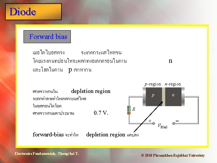
Diode Reverse bias ถา pn junction ไดรบไบอสกลบ อเลกตรอนและ โฮลจะวงออกจากกน กระแสจงไมไหล p-region n-region p n R - reverse-bias จะทำให Electronics Fundamentals, Thongchai T. VBIAS + depletion region กวางขน © 2010 Phranakhon Rajabhat Univeristy
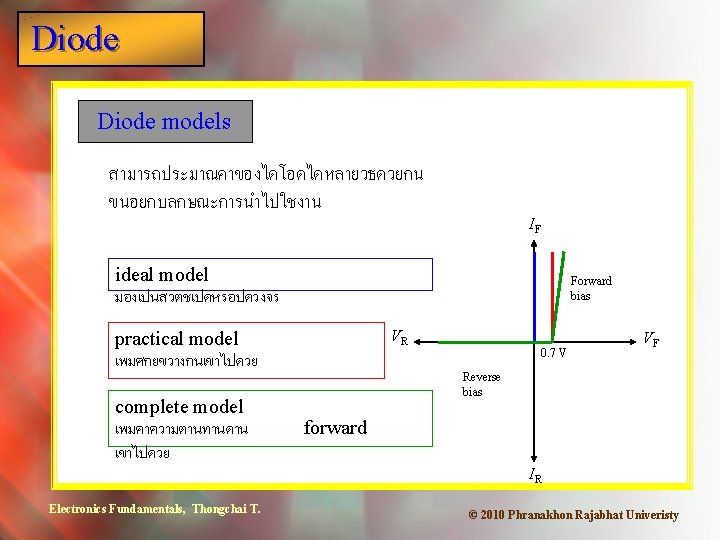
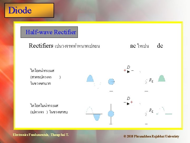
Diode characteristics ลกษณะการนำกระแสดาน forward และ reverse แสดงใน V-I characteristic curve IF VBR (breakdown) Forward bias VR 0. 7 V Reverse bias VF Barrier potential IR Electronics Fundamentals, Thongchai T. © 2010 Phranakhon Rajabhat Univeristy
Diode Full-wave Rectifier ใชหมอแปลงแบบ center-tapped และใชไดโอดสองตว D 1 F Vsec 2 Electronics Fundamentals, Thongchai T. D 2 RL © 2010 Phranakhon Rajabhat Univeristy
Diode Summary Peak inverse voltage Diodes must be able to withstand a reverse voltage when they are reverse biased. This is called the peak inverse voltage (PIV). The PIV depends on the type of rectifier circuit and the maximum secondary voltage. For example, in a full-wave circuit, if one diode is conducting (assuming 0 V drop), the other diode has the secondary voltage across it as you can see from applying KVL around the green path. Notice that Vp(sec) = 2 Vp(out) for the full-wave circuit because the output is referenced to the center tap. Electronics Fundamentals, Thongchai T. 0 V Vsec © 2010 Phranakhon Rajabhat Univeristy
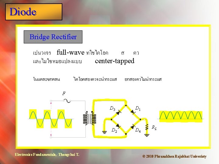
Diode Summary Peak inverse voltage For the bridge rectifier, KVL can be applied to a loop that includes two of the diodes. Assume the top diode is conducting (ideally, 0 V) and the lower diode is off. The secondary voltage will appear across the non-conducting diode in the loop. Notice that Vp(sec) = Vp(out) for the bridge because the output is across the entire secondary. 0 V Vsec Electronics Fundamentals, Thongchai T. © 2010 Phranakhon Rajabhat Univeristy
Diode Summary Power supplies By adding a filter and regulator to the basic rectifier, a basic power supply is formed. Typically, a large electrolytic capacitor is used as a filter before the regulator, with a smaller one following the regulator to complete filtering action. IC regulator F D 3 D 1 7805 D 2 Electronics Fundamentals, Thongchai T. D 4 C 1 1000 m. F C 2 1 m. F © 2010 Phranakhon Rajabhat Univeristy
Diode Summary Special-purpose diodes Special purpose diodes include Zener diodes – used for establishing a reference voltage Varactor diodes – used as variable capacitors Light-emitting diodes – used in displays Photodiodes – used as light sensors Electronics Fundamentals, Thongchai T. © 2010 Phranakhon Rajabhat Univeristy
Diode Summary Troubleshooting power supplies Begin troubleshooting by analyzing the symptoms and how it failed. Try to focus on the most likely causes of failure. A power supply has no output, but was working until a newly manufactured PC board was connected to it. (a) Analyze possible failures. (b) Form a plan for troubleshooting. IC regulator F D 3 D 1 7805 D 2 Electronics Fundamentals, Thongchai T. D 4 C 1 1000 m. F C 2 1 m. F © 2010 Phranakhon Rajabhat Univeristy
Diode Summary Troubleshooting power supplies The supply had been working, so the problem is not likely to be an incorrect part or wiring problem. The failure was linked to the fact that a new PC board was connected to it, which points to a possible overloading problem. If the load was too much for the supply, it is likely a fuse would have blown, or a part would likely have overheated, accounting for the lack of output. IC regulator F D 3 D 1 7805 D 2 Electronics Fundamentals, Thongchai T. D 4 C 1 1000 m. F C 2 1 m. F © 2010 Phranakhon Rajabhat Univeristy
Diode Summary Troubleshooting power supplies Based on the analysis, a sample plan is as follows. (It can be modified as circumstances warrant. ) 1. Disconnect power and check the fuse. If it is bad, replace it. Before reapplying power, remove the load, open the power supply case, and look for evidence of overheating (such as discolored parts or boards). If no evidence of overheating proceed. 2. Check the new pc board (the load) for a short or overloading of the power supply that would cause the fuse to blow. Look for evidence of overheating. 3. Verify operation of the supply with measurements (see next slide). Electronics Fundamentals, Thongchai T. © 2010 Phranakhon Rajabhat Univeristy
Diode Summary Troubleshooting power supplies The analysis showed that a likely cause of failure was due to an overload. For the measurement step, it may be as simple as replacing the fuse and confirming that the supply works. After replacing the fuse: Reapply power to the supply but with no load. If the output is okay, put a resistive test load on the power supply and measure the output to verify it is operational. If the output is correct, the problem is probably with the new pc board. If not, you will need to further refine the analysis and plan, looking for an internal problem. Electronics Fundamentals, Thongchai T. © 2010 Phranakhon Rajabhat Univeristy
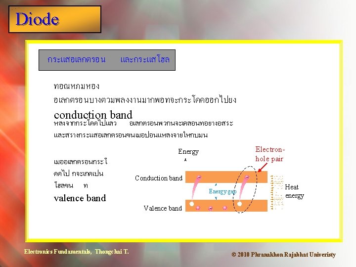
Diode Selected Key Terms Majority carrier The most numerous charge carrier in a doped semiconductor material (either free electrons or holes. Minority carrier The least numerous charge carrier in a doped semiconductor material (either free electrons or holes. PN junction The boundary between n-type and p-type semiconductive materials. Diode An electronic device that permits current in only one direction. Electronics Fundamentals, Thongchai T. © 2010 Phranakhon Rajabhat Univeristy
Diode Selected Key Terms Barrier potential The inherent voltage across the depletion region of a pn junction diode. Forward bias The condition in which a diode conducts current. Reverse bias The condition in which a diode prevents current. Full-wave rectifier A circuit that converts an alternating sinewave into a pulsating dc consisting of both halves of a sine wave for each input cycle. Electronics Fundamentals, Thongchai T. © 2010 Phranakhon Rajabhat Univeristy
Diode Selected Key Terms Bridge rectifier A type of full-wave rectifier consisting of diodes arranged in a four corner configuration. Zener diode A type of diode that operates in reverse breakdown (called zener breakdown) to provide a voltage reference. Varactor A diode used as a voltage-variable capacitor. Photodiode A diode whose reverse resistance changes with incident light. Electronics Fundamentals, Thongchai T. © 2010 Phranakhon Rajabhat Univeristy
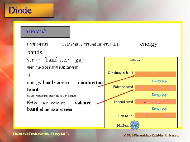
Diode Quiz 1. An energy level in a semiconductor crystal in which electrons are mobile is called the a. barrier potential. b. energy band. c. conduction band. d. valence band. Electronics Fundamentals, Thongchai T. © 2010 Phranakhon Rajabhat Univeristy
Diode Quiz 2. A intrinsic silicon crystal is a. a poor conductor of electricity. b. an n-type of material. c. a p-type of material. d. an excellent conductor of electricity. Electronics Fundamentals, Thongchai T. © 2010 Phranakhon Rajabhat Univeristy
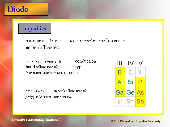
Diode Quiz 3. A small portion of the Periodic Table is shown. The elements highlighted in yellow are a. majority carriers. b. minority carriers. c. trivalent elements. d. pentavalent elements. Electronics Fundamentals, Thongchai T. © 2010 Phranakhon Rajabhat Univeristy
Diode Quiz 4. At room temperature, free electrons in a p-material a. are the majority carrier. b. are the minority carrier. c. are in the valence band. d. do not exist. Electronics Fundamentals, Thongchai T. © 2010 Phranakhon Rajabhat Univeristy
Diode Quiz 5. The breakdown voltage for a silicon diode is reached when a. the forward bias is 0. 7 V. b. the forward current is greater than 1 A. c. the reverse bias is 0. 7 V. d. none of the above. Electronics Fundamentals, Thongchai T. © 2010 Phranakhon Rajabhat Univeristy
Diode Quiz 6. The circuit shown is a a. half-wave rectifier. b. full-wave rectifier. c. bridge rectifier. d. zener regulator. Electronics Fundamentals, Thongchai T. © 2010 Phranakhon Rajabhat Univeristy
Diode Quiz 7. PIV stands for a. Positive Ion Value. b. Programmable Input Varactor. c. Peak Inverse Voltage. d. Primary Input Voltage. Electronics Fundamentals, Thongchai T. © 2010 Phranakhon Rajabhat Univeristy
Diode Quiz 8. A type of diode used a a voltage-variable capacitor is a a. varactor. b. zener. c. rectifier. d. LED. Electronics Fundamentals, Thongchai T. © 2010 Phranakhon Rajabhat Univeristy
Diode Quiz 9. If one of the four diodes in a bridge rectifier is open, the output will a. be zero. b. have ½ as many pulses as normal. c. have ¼ as many pulses as normal. d. be unaffected. Electronics Fundamentals, Thongchai T. © 2010 Phranakhon Rajabhat Univeristy
Diode Quiz 10. When troubleshooting a power supply that has a bridge rectifier, begin by a. replacing the bridge rectifier. b. replacing the transformer. c. making measurements. d. analyzing the symptoms and how it failed. Electronics Fundamentals, Thongchai T. © 2010 Phranakhon Rajabhat Univeristy
Diode Quiz Answers: Electronics Fundamentals, Thongchai T. 1. c 6. b 2. a 7. c 3. c 8. a 4. b 9. b 5. d 10. d © 2010 Phranakhon Rajabhat Univeristy