Electronics Cooling MPE 635 Mechanical Power Engineering Dept


 steel cylinder")


 From the rate equations, it is clear that enhancing heat transfer")
 In electronics cooling fins are usually considered to have an insulated")
 ηf = (tanh ml )/ml Where m = and l and")


- Slides: 33
Electronics Cooling MPE 635 Mechanical Power Engineering Dept.
Course Goals 1. To establish fundamental understanding of heat transfer in electronic equipment. 2. To select a suitable cooling processes for electronic components and systems. 3. To increase the capabilities of post graduate students in design and analysis of cooling of electronic packages. 4. To analysis thermal failure for electronic components and define the solution.
4. Conduction Heat Transfer
Fourier Equation for Conduction Heat Transfer • Conduction is one of the heat transfer modes. Concerning thermal design of electronic packages conduction is a very important factor in electronics cooling specially conduction in PCB’s and chip packages. • The basic law governing the heat transfer by conduction is Fourier’s law
Energy Equation As a system, energy balance may be applied on any electronic component. A typical energy balance on a control volume can be described as shown in the following equation. And the amount of energy flowing into or out of the system can be described by the Fourier’s law.
Energy Equation in Cartesian Coordinates
Energy Equation in Cartesian Coordinates • For a constant thermal conductivity the heat equation could be rewritten as Where α = k/ ρ Cp is thermal diffusivity.
Energy Equation in Cylindrical Coordinates
Energy Equation in Spherical Coordinates
Special cases of one dimensional conduction • Boundary conditions Some of the boundary conditions usually met in heat transfer problems for one dimensional system are described below. These conditions are set at the surface x = 0, assuming transfer process in the positive direction of x axis with temperature distribution which may be time dependent, designated as T(x, t) • One dimensional steady state conduction without heat generation • One dimensional steady state conduction with uniform heat generation
Boundary conditions • Constant surface temperature The surface is maintained at a fixed temperature Ts. It is commonly called a Dirichlet condition, which is the boundary condition of the first case. It can be approximated as a surface in contact with a solid or a liq uid in a changing phase state (boiling, evaporating, melting or freezing) therefore the temperature, accompanied with heat transfer process, is constant.
Boundary conditions • Constant surface heat flux Finite heat flux In this case fixed or constant heat flux q" at the surface is described. At which the heat flux is a function of the temperature gradient at the surface by Fourier's law. This type of boundary condition is called Neumann condition. Examples of constant surface heat flux are: Adiabatic heat flux Convection surface condition
One dimensional steady state conduction without heat generation • The assumptions made for this kind of analysis are: One dimensional Steady state No heat generation Constant material properties
One dimensional steady state conduction in Cartesian coordinates without heat generation
Example 4. 1 • Calculate the maximum temperature the transistor base attains if it dissipates 7. 5 W through the bracket shown in the Figure below. All dimensions are in mm and the bracket is made of duralumin.
Solution: Given Dimensions on the figure. q = 7. 5 W tw = 50 ºC k = 164 W/m. k As the dimensions of the bracket is very small we can consider that heat transfer is a one dimensional conduction through the sides of the bracket. For the dimensions shown on the figure L = 15 + 15 = 45 mm = 0. 045 m w = 20 mm = 0. 02 m δ = 5 mm = 0. 005 m A = w x δ = 1 x 10 -4 m 2 From the above values the only unknown in equation 4. 23 is the temperature of the transistor base. q = k A (tb - tw)/L tb = tw + (q. L/k. A) tb = 50 + (7. 5 x 0. 045/164 x 10 -4) tb = 70. 58 ºC
One dimensional steady state conduction in cylindrical coordinates without heat generation Considering the assumptions stated before, d. T/dr is constant and heat flow only in one spatial coordinates the general form becomes, Where subscripts 1 and 2 refer to the inner and the outer surfaces respectively.
Example A hollow stainless (25 % Cr , 20 % Ni ) steel cylinder 35 mm long has an inner diameter of 50 mm and outer diameter of 105 mm. a group of resistors that generate 10 W is to be mounted on the inside surface of the cylinder as shown in figure. If the resistors temperature is not to exceed 100 º C find the maximum allowed temperature on the outer surface of the cylinder.
Solution • thermal conductivity of 25 % Cr , 20 % Ni stainless steel is 12. 8 W/m. K considering the one D conduction equation, The only unknown is the temperature of the outside surface of the cylinder. To= 100 – 10 × (ln (52. 5/25)/ (2π × 12. 8 × 0. 035) To = 100 – 2. 64 = 97. 36 º C
One dimensional steady state conduction in spherical coordinates without heat generation • The same assumptions are applied to the spherical system giving the following solution • Where the subscripts i and o refer to the inside and the outside surfaces respectively.
One dimensional steady state conduction with uniform heat generation • The assumptions made for this kind of analysis are: One dimensional Steady state Uniform heat generation Constant material properties
One dimensional steady state conduction in Cartesian coordinates with uniform heat generation q =q''' ×A × L = Ts – Tc/(Lc/kc Ac)
One dimensional steady state conduction in cylindrical coordinates with uniform heat generation T = Ts + q''' / 4 k( ro 2 – r 2 ) For a convective boundaries T = T∞ + q''' / 4 k( ro 2 – r 2 ) + q''' ro/ 2 h
Extended surfaces (Fins) From the rate equations, it is clear that enhancing heat transfer could be done by several methods: Increasing the temperature difference Increasing the heat transfer coefficient Increasing the surface area A , Fins are used to add a secondary surface to the primary surface and thus increasing the heat transfer area. In electronic equipment cooling straight rectangular fins are mostly used and are done of good conducting material to attain the root temperature through the fins in order to increase the heat transferred. Fins used in electronics cooling are usually used of aluminum and are quite thin about 1. 3 to 1. 5 mm thick.
Extended surfaces (Fins) In electronics cooling fins are usually considered to have an insulated tip. The heat transferred by fins are expressed in its effectiveness which is defined as ηf = qf / qmax where qf is the heat actually transferred by the fin and qmax is the maximum heat that could be dissipated by the fin (i. e. when the fin has a uniform temperature equals to the root temperature tr.
Extended surfaces (Fins) ηf = (tanh ml )/ml Where m = and l and b are defined on the fin sketch. Also the fin effectiveness could be considered as the fraction of the total surface area of the fin Af that is effective for the heat transfer by convection maintained at root temperature tr. ηf = Af, eff/Af, tot q = h [( Atot – Af) + ηf Af] (tr ta) = ηo Atot h (tr ta) Where ηo = 1 – (Af/Atot) (1 ηf ) If the fin is of convective tip a correction could be done as lc= l + (t/2)
Fin Geometries Fin descriptions
Factors affected on the fin selection Heat transfer/pressure drop
Factors affected on the fin selection Size figure of merit
Factors affected on the fin selection Weight figure of merit.
Factors affected on the fin selection A relative comparison of the fin configurations, based on all the factors discussed is critical in determining the proper design. Comparison of All Parameters Fin Configuration P Size Weight Cost Average Straight 1 5 4 2 3 Offset 4 3 3 4 3. 5 Pin 5 1 3 Wavy 3 4 2 3 3 Louver 2 2 1 5 2. 5
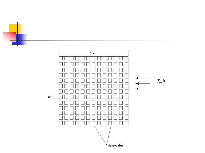
Example • In order to enhance the heat transfer in logic chips a heat sink is attached to the chip surface in order to increase the surface area available for convection, the heat sink consists of an array of square fins of width w and the sum of the fin spacing and its width is the fin pitch S, the fins are attached to the chip causing a contact resistance R''t, c. • Consider the chip width = 16 mm, cooling is provided by a dielectric liquid with T∞= 25 °C and h =1500 W/m 2. k and the heat sink is fabricated from copper (k= 400 W/m. k) and its characteristic dimension are w = 0. 25 mm and S = 0. 50 mm and Lf = 6 mm , and Lb = 3 mm