
ELECTRONIC STICK FOR BLIND PEOPLE Submitted By N
ELECTRONIC STICK FOR BLIND PEOPLE Submitted By N. Jayaprakash Under guidance of V. Anusha Asst. Professor Internal guide D. Sudhakar Asst. Professor Co- ordinate
INTRODUCTION • The main aim of this project is to detect the obstacle in front of the electronic stick and giving the alarm • This will assist the blind persons during the walk and provides an alarm if any hurdle is detected with-In the set range • This system mainly consists of a regulated power supply, IR transmitter, IR receiver, control circuit and the output driver circuit • The IR sensor detects the presence of an obstacle in front of the person
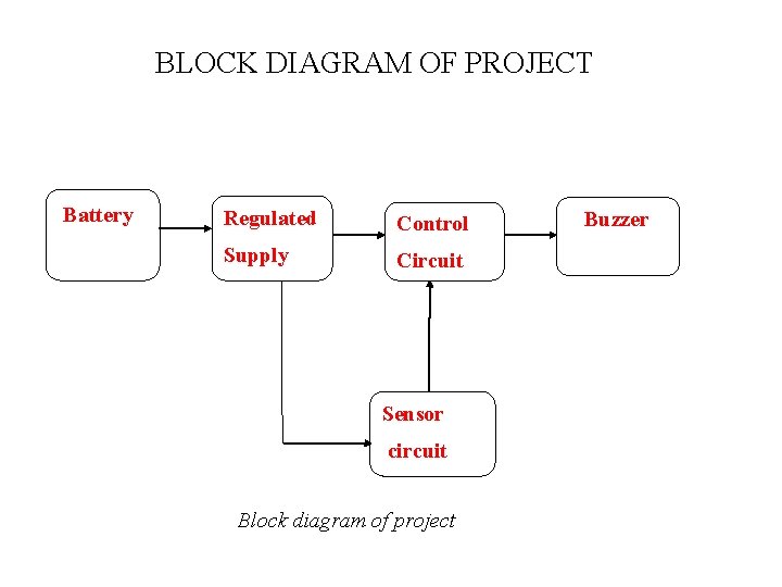
BLOCK DIAGRAM OF PROJECT Battery Regulated Control Supply Circuit Sensor circuit Block diagram of project Buzzer
MAJOR COMPONENTS INFORMATION ü Integrated Circuit 555 ü Light Emitting Diode (LED) ü TSOP 1738 IR receiver ü Comparator ü Voltage Regulator
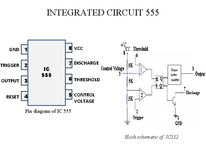
INTEGRATED CIRCUIT 555 GND 1 8 VCC TRIGGER 2 7 DISCHARGE OUTPUT 3 RESET 4 IC 555 6 THRESHOLD 5 CONTROL VOLTAGE Pin diagram of IC 555 Block schematic of IC 555
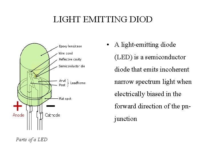
LIGHT EMITTING DIOD • A light-emitting diode (LED) is a semiconductor diode that emits incoherent narrow spectrum light when electrically biased in the forward direction of the pnjunction Parts of a LED
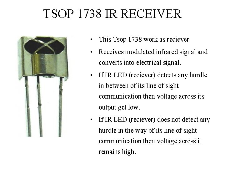
TSOP 1738 IR RECEIVER • This Tsop 1738 work as reciever • Receives modulated infrared signal and converts into electrical signal. • If IR LED (reciever) detects any hurdle in between of its line of sight communication then voltage across its output get low. • If IR LED (reciever) does not detect any hurdle in the way of its line of sight communication then voltage across it remains high.
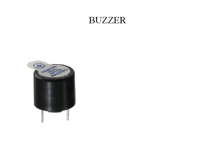
BUZZER
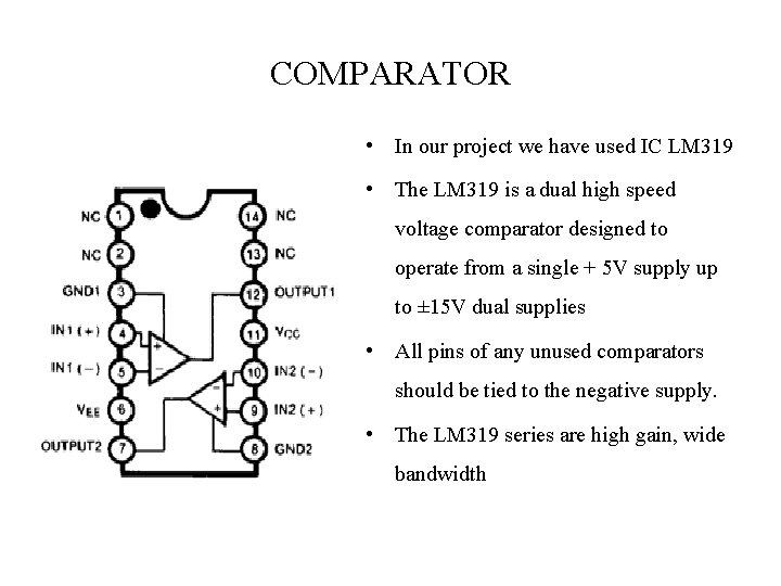
COMPARATOR • In our project we have used IC LM 319 • The LM 319 is a dual high speed voltage comparator designed to operate from a single + 5 V supply up to ± 15 V dual supplies • All pins of any unused comparators should be tied to the negative supply. • The LM 319 series are high gain, wide bandwidth
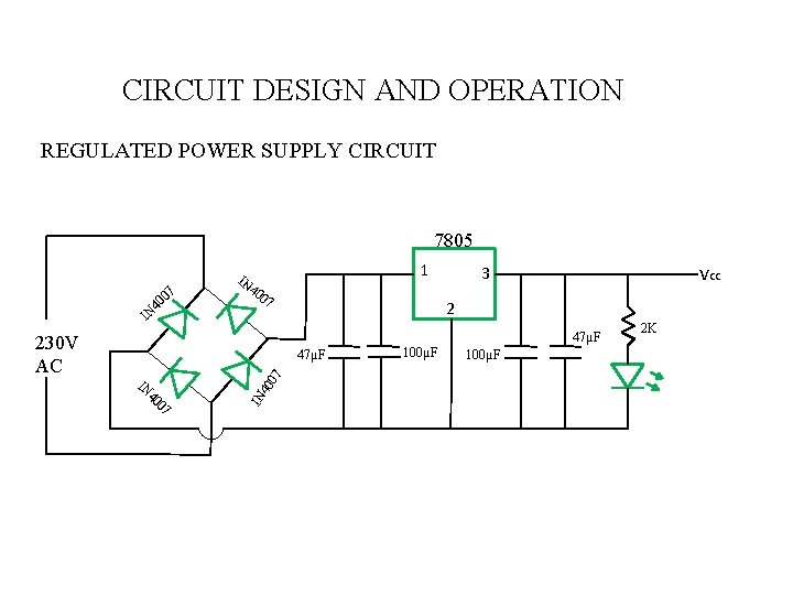
CIRCUIT DESIGN AND OPERATION REGULATED POWER SUPPLY CIRCUIT 7805 07 40 IN IN 1 40 07 vcc 3 2 47µF 230 V AC 07 40 IN IN 40 07 47µF 100µF 2 K
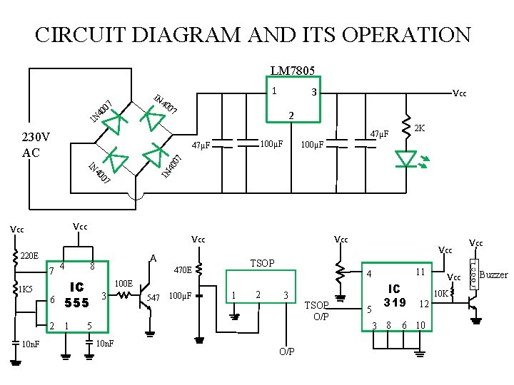
CIRCUIT DIAGRAM AND ITS OPERATION LM 7805 IN 1 40 07 40 IN vcc 3 07 2 2 K 47µF 230 V AC 100µF 07 40 IN IN 40 07 47µF vcc 220 E 7 4 1 K 5 6 vcc A 8 IC 555 2 1 10 n. F vcc TSOP 470 E 547 100µF 1 2 3 5 10 n. F 11 4 100 E 3 vcc O/P TSOP O/P 5 IC 319 3 8 12 6 10 vcc 10 K vcc Buzzer
ADVANTAGES Ø Multiplexers are used to sense obstacles in different directions simultaneously. This means, the blind person might receive different signals on obstacles in different directions around him. Ø The moisture sensing electrodes sense the moist soil or stagnant water. This can be especially helpful during the rainy season. It also contains micro-switches, to detect manholes.
FUTURE SCOPE Ø Technology created reading machines, talking books, and computers that translate Braille. Ø Communications technologies were easier to invent and consequently were brought to market Ø Technologies available for blind navigation are insufficiently developed, adapted, and marketed.
CONCLUSIONS Ø Electronic walking stick for blind people helps the blind people when the obstacle occurs at in front the person. Ø The stick gives signal to the person by buzzer sound or vibration when it detects the obstacle. Ø Without the help of any other person the blind people can walk easily.
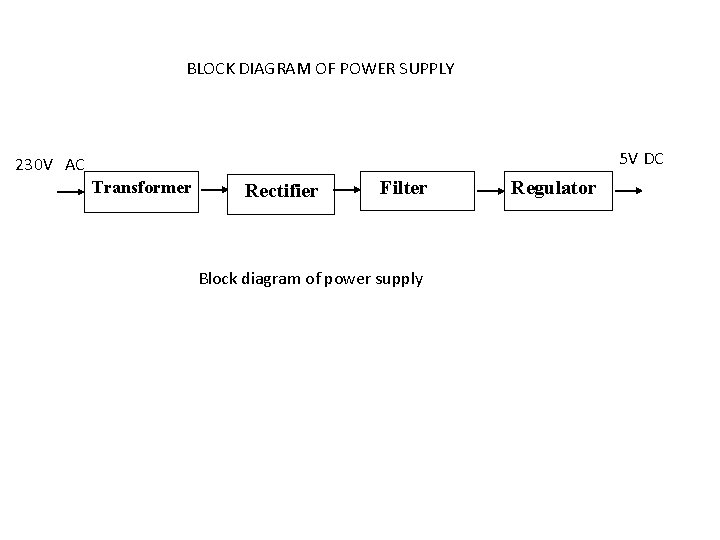
BLOCK DIAGRAM OF POWER SUPPLY 5 V DC 230 V AC Transformer Rectifier Filter Block diagram of power supply Regulator
INTEGRATED CIRCUIT 555 • IC 555 timer IC along with Infra red LED which is going to transmit signal • This IC consists of two comparators that drive the set(S) and reset(R) terminals of a flip flop. • The Q output is available as the overall output. Q' drives the discharge transistor • The reference voltage of comparator 1 is fixed at (2/3)V+ and that of comparator 2 is fixed at (1/3)V+.
- Slides: 16