Electronic Product Design Do it Yourself Finally Dr


")


- Slides: 18
Electronic Product Design Do it Yourself Finally… Dr. Y S Rao ysrao@spit. ac. in LAUNCH!!
Digitization of Objects Analog vs. Digital
Beware of the computer! • computers + So. Cs = hardware / software mix • complete change in device interaction • ever-growing number of critical applications 3
On/OFF Control
ON/OFF Switch (current)
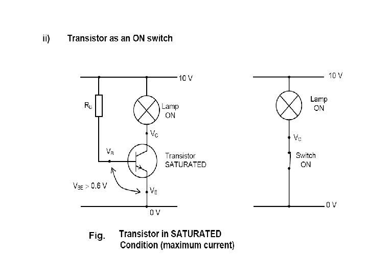
Transistor can act as a Switch
EX: Light Failure Warning System using Transistor as a Switch
Introducing Delay in ON/OFF RC constants A simple resistor and capacitor can be used to control the amount of time that it takes for an output signal to reach a specific voltage. This is particularly useful when you reset a device, to ensure, for example, that a pin does not reach logic high (0. 7*VCC for CMOS) or pass logic low (0. 3*VCC for CMOS) before x microseconds, giving the rest of the system time to perform some other tasks before-hand. This simple calculator will tell you how many milliseconds are required to reach the specific output voltage (Vc), based on the supply voltage (V), the resistor value (R) and the capacitor value (C). The resistor value is assumed to be in K ohms, the capacitor in microfarads, and the calculated delay will be in milliseconds. The formula used to calculate the delay is: t = -log((V-Vc)/V)R*C To calculate Vc at a specific time, the formula can be modified to: Vc = V-(V*exp(-t/(R*C)))
Example The following image shows the results of a 2. 0 K resistor and a 0. 1 u. F capacitor using a 3. 3 V supply. The blue line is the HW reset, and the yellow line is the output of the RC pair. You can see that it takes about 230 us (. 23 ms) to reach 2. 3 V, which is roughly logic high on a CMOS device using 3. 3 V logic (0. 7 VCC). Issue of Tolerance
Transistor with Delay
MOSFET Switch
Digital ICs Sinking & Sourcing
Noise Margin Ability to tolerate noise without changes in output voltage
A Typical Microcontroller RAM Flash EEPROM Clock I/O Core Reset Power Timers Comm Analog 15
Technology Comparison
Integration
IC Packages