ELECTRONIC INSTRUMENTATION EKT 3144 WEEK 9 CHAPTER 4


")

")

 Bit 1 Bit 0 (LSB) 22 21")
 Bit 2 (2/7) Bit 0 (1/7) Analog")


")


- Slides: 38
ELECTRONIC INSTRUMENTATION EKT 314/4 WEEK 9 : CHAPTER 4 DATA ACQUISITION AND CONVERSION
Chapter 4 Problem Statement �Do not know the overall figure of Data Acquisition System �Do not know how ADC work �Do not know how DAC work �To figure out how complex system works �To know what is Sample and Hold
Chapter 4 Objectives �To figure out the DAS �To investigate how ADC work �To investigate how DAC work �To know the function of Multiplexer �To know how Sample & Hold concept work
Chapter 4 Content �Introduction �Single Channel Data Acquisition Systems �Multi Channel Data Acquisition Systems �Data Conversion �Multiplexers �Sample and Hold
Chapter 4 Content �Introduction �DAS Parts �General Block Diagram �Objectives �Single Channel DAS �. �.
Introduction: Parts �Typical DAS consist of: �Sensors �Signal Conditioning �Data Conversion �Data Processing �Multiplexing �Data Handling and Associated Transmission �Storage System �Display System
Introduction: General Block Diagram
Introduction: Objectives �Objective of DAS �To acquire necessary data at correct speed & time. �To inform operator all data efficiently �To monitor complete system operation �To provide effective human communication system and identify problem areas �To enable data collection, analyse and storing �To enable unit performance indices computation.
Chapter 4 Content �Introduction �Single Channel DAS �Parts �Block Diagram �Characteristic �Multi Channel DAS �. �.
Single Channel DAS: Parts �Consist of: �Signal Conditioner �Analog to Digital Converter �Buffer �Display / Record Devices
Single Channel DAS: Block Diagram
Single Channel DAS: Characteristic �Perform repetitive conversion at free running, internally determined rate �Outputs are in digital code words: �Data �Over Range Indication �Polarity Information �Output Validity Status
Chapter 4 Content �. �Single Channel DAS �Multi Channel DAS �Parts �Block Diagram �Characteristics �Comparison with Single Channel �Data Conversion �.
Multi Channel DAS: Parts �Consist of: �Signal Conditioner �Multiplexer �Sample-Hold Circuit �Analog to Digital Converter �Logic Circuit �Buffer �Processor/Controller
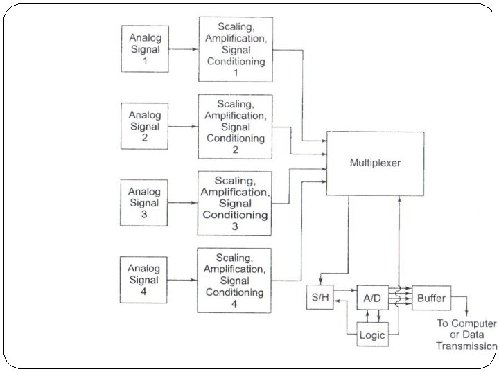
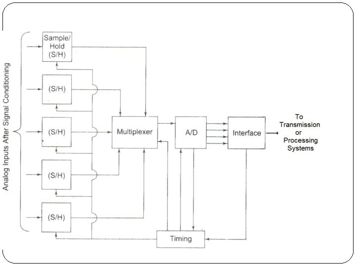
Multi Channel DAS: Block Diagram
Multi Channel DAS: Characteristics �Input from Multiple Data Source �Work based on Input Sampling �Multiple Input Multiplexed (TDM) before processed �Can be divided into two different system type based on location of A/D-Multiplexer: �Multiple Input – A/D(s) – Multiplexer – Processor �Multiple Input – Multiplexer – A/D - Processor
Multi Channel DAS: Characteristics
DAS Comparison Single Channel Multiple channel �Simple �Complex and need to �Low parts count be designed wisely to avoid high cost �Faster since data to be read already in digital form �Data always available �Less accurate but acceptable if sampling condition acceptable �Slower since coding need to be change (BCD to Digital) �Data availability time cannot be controlled �Accurate
Chapter 4 Content �. �Multiple Channel DAS �Data Conversion �Digital to Analog Converter (DAC) �Analog to Digital Converter (ADC) �Multiplexer �. �.
Data Conversion �Important aspect of digital data processing �ADC used to encode analog signal to equivalent digital values (signals) �DAC used to decode digital values (signals) to produce equivalent analog signal. �Both conversion have condition: �Upper bound �Lower bound
Chapter 4 Content �. �Multiple Channel DAS �Data Conversion �Digital to Analog Converter (DAC) �Analog to Digital Converter (ADC) �Multiplexer �. �.
DAC: Working Principle �Input is Digital, Output is Analog �Digital Value converted to Equivalent Analog Value �Can Use: �Variable Resistor Network �Opamp (Summing Circuit)
DAC: Variable Resistor Network Bit 2 (MSB) Bit 1 Bit 0 (LSB) 22 21 20 4/7 2/7 1/7 �Binary Equivalent Weight (LSB) �n – number of bit
DAC: Variable Resistor Network Bit 3 (4/7) Bit 2 (2/7) Bit 0 (1/7) Analog Value Vref = +7 V Vref = +14 V 0 0 0 Vref(0) 0 0 1 Vref(1/7) 1 2 0 1 0 Vref(2/7) 2 4 0 1 1 Vref(1/7 + 2/7) 3 6 1 0 0 Vref(4/7) 4 8 1 0 1 Vref(4/7 + 1/7) 5 10 1 1 0 Vref(4/7 + 2/7) 6 12 1 1 1 Vref(4/7 + 2/7 + 1/7) 7 14
DAC: VRN Equiv. Circuit
DAC: VRN – Millman’s theorem �Voltage appearing at any node in a resistive network is equal to the summation of the current entering the node divided by the summation of the conductances connected to the node.
DAC: VRN – Millman’s Theorem �Suppose we have digital value of 001 to be converted into analog voltage �Value 0 = 0 Volt �Value 1 = +7 Volt
DAC: VRN – Millman’s Theorem �Applying Millman’s Theorem:
DAC: Ladder Type Network R-2 R LADDER Binary ladder
DAC: Ladder Type Network �Assignment 1: R-2 R Ladder �Assignment 2: Binary Ladder �*Submit in Monday Lab Session
Chapter 4 Content �. �Multiple Channel DAS �Data Conversion �Digital to Analog Converter (DAC) �Analog to Digital Converter (ADC) �Multiplexer �. �.
ADC: Working Principle �Based on Successive Approximation Method �Compare bit by bit (from highest bit to lowest bit) �Start Signal �Stop Signal
ADC: Block Diagram
ADC Operation � Start=1, SAR=0000 b, Ring. Counter = 0, Vref=5 V, Vin=1 V Oper D 7 Set D 6 Set D 5 Set D 4 Set D 3 Set D 2 Set D 7 D 6 D 5 D 4 D 3 D 2 D 1 D 0 1 0 0 0 0 1 Vout Cmp 2. 5 Vin< 1 Vin> 1 Vin<
ADC Operation: 1 V in, 5 V ref
ELECTRONIC INSTRUMENTATION EKT 314/4 WEEK 9 : CHAPTER 4 END