Electromagnetic Interaction of Particles with Matter Z 2


/d. E’/ (E) Probability f(E) for loosing")
: Probability for energy loss in matter of thickness D. Landau")
")


 1 stack =")


: Gas volume with parallel E and B Field. B for")
 Event display of a Au Au collision at CM energy of")


- Slides: 45
Electromagnetic Interaction of Particles with Matter Z 2 electrons, q=-e 0 M, q=Z 1 e 0 Interaction with the atomic electrons. The incoming particle loses energy and the atoms are excited or ionized. 3/12/2021 Interaction with the atomic nucleus. The particle is deflected (scattered) causing multiple scattering of the particle in the material. During this scattering a Bremsstrahlung photon can be emitted. In case the particle’s velocity is larger than the velocity of light in the medium, the resulting EM shockwave manifests itself as Cherenkov Radiation. When the particle crosses the boundary between two media, there is a probability of the order of 1% to produced and X ray photon, called Transition radiation. 5
Bethe Bloch Formula Electron Spin Density effect. Medium is polarized Which reduces the log. rise. W. Riegler/CERN 6
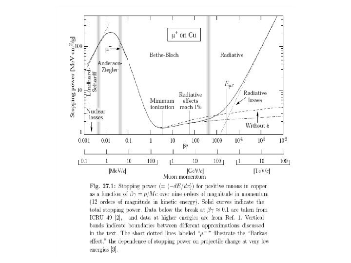
Bethe Bloch Formula Für Z>1, I 16 Z 0. 9 e. V For Large the medium is being polarized by the strong transverse fields, which reduces the rise of the energy loss density effect Characteristics of the energy loss as a function of the particle velocity ( ) 1/ At large Energy Transfers (delta electrons) the liberated electrons can leave the material. In reality, Emax must be replaced by Ecut and the energy loss reaches a plateau (Fermi plateau). The specific Energy Loss 1/ρ d. E/dx • first decreases as 1/ 2 • increases with ln for =1 • is independent of M (M>>me) • is proportional to Z 12 of the incoming particle. • is independent of the material (Z/A const) • shows a plateau at large (>>100) • d. E/dx 1 -2 x ρ [g/cm 3] Me. V/cm W. Riegler/CERN Energy Loss by Excitation and Ionization 7
Bethe Bloch Formula, a few Numbers: For Z 0. 5 A 1/ d. E/dx 1. 4 Me. V cm 2/g for ßγ 3 1/ Example : Iron: Thickness = 100 cm; ρ = 7. 87 g/cm 3 d. E ≈ 1. 4 * 100* 7. 87 = 1102 Me. V A 1 Ge. V Muon can traverse 1 m of Iron This number must be multiplied with ρ [g/cm 3] of the Material d. E/dx [Me. V/cm] W. Riegler/CERN Energy Loss by Excitation and Ionization 8
Energy Loss as a Function of the Momentum Energy loss depends on the particle velocity and is ≈ independent of the particle’s mass M. The energy loss as a function of particle Momentum P= Mcβγ IS however depending on the particle’s mass By measuring the particle momentum (deflection in the magnetic field) and measurement of the energy loss on can measure the particle mass Particle Identification ! W. Riegler/CERN Energy Loss by Excitation and Ionization 9
Range of Particles in Matter Particle of mass M and kinetic Energy E 0 enters matter and looses energy until it comes to rest at distance R. » Independent of the material Bragg Peak: For >3 the energy loss is constant (Fermi Plateau) If the energy of the particle falls below =3 the energy loss rises as 1/ 2 Towards the end of the track the energy loss is largest Cancer Therapy. W. Riegler/CERN Energy Loss by Excitation and Ionization 10
Range of Particles in Matter Average Range: Towards the end of the track the energy loss is largest Bragg Peak Cancer Therapy Carbon Ions 330 Me. V Relative Dose (%) Photons 25 Me. V Depth of Water (cm) W. Riegler/CERN Energy Loss by Excitation and Ionization 11
Fluctuations of the Energy Loss d (E, E’)/d. E’/ (E) Probability f(E) for loosing energy between E’ and E’+d. E’ in a single interaction is given by the differential crossection d (E, E’)/d. E’/ (E) which is given by the Rutherford crossection at large energy transfers Excitation and ionization Scattering on free electrons P(E, ) W. Riegler/CERN Energy Loss by Excitation and Ionization 12
Landau Distribution P( ): Probability for energy loss in matter of thickness D. Landau distribution is very asymmetric. Average and most probable energy loss must be distinguished ! Measured Energy Loss is usually smaller that the real energy loss: 3 Ge. V Pion: E’max = 450 Me. V A 450 Me. V Electron usually leaves the detector. W. Riegler/CERN Energy Loss by Excitation and Ionization 13
Landau Distribution LANDAU DISTRIBUTION OF ENERGY LOSS: Counts 4 cm Ar-CH 4 (95 -5) 5 bars 6000 PARTICLE IDENTIFICATION Requires statistical analysis of hundreds of samples Counts 15 Ge. V/c 6000 protons electrons N = 460 i. p. FWHM~250 i. p. 4000 2000 0 0 0 500 1000 N (i. p. ) 0 For a Gaussian distribution: N ~ 21 i. p. FWHM ~ 50 i. p. 500 1000 N (i. p) I. Lehraus et al, Phys. Scripta 23(1981)727 W. Riegler/CERN Energy Loss by Excitation and Ionization 14
Particle Identification Measured energy loss ‘average’ energy loss In certain momentum ranges, particles can be identified by measuring the energy loss. W. Riegler/CERN Energy Loss by Excitation and Ionization 15
Cloud Chamber Wilson Cloud Chamber 1911 W. Riegler/CERN 19
Cloud Chamber X-rays, Wilson 1912 W. Riegler/CERN Alphas, Philipp 1926 20
Cloud Chamber Magnetic field 15000 Gauss, chamber diameter 15 cm. A 63 Me. V positron passes through a 6 mm lead plate, leaving the plate with energy 23 Me. V. The ionization of the particle, and its behaviour in passing through the foil are the same as those of an electron. Positron discovery, Carl Andersen 1933 W. Riegler/CERN 21
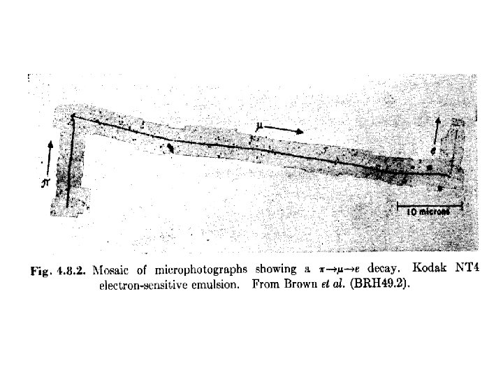
Nuclear Emulsion Film played an important role in the discovery of radioactivity but was first seen as a means of studying radioactivity rather than photographing individual particles. Between 1923 and 1938 Marietta Blau pioneered the nuclear emulsion technique. E. g. Emulsions were exposed to cosmic rays at high altitude for a long time (months) and then analyzed under the microscope. In 1937, nuclear disintegrations from cosmic rays were observed in emulsions. The high density of film compared to the cloud chamber ‘gas’ made it easier to see energy loss and disintegrations. W. Riegler/CERN 22
A special event
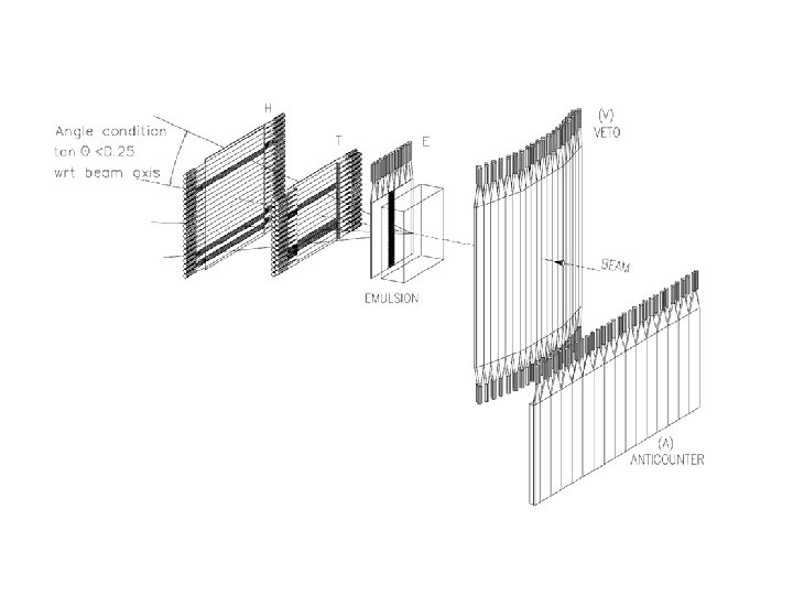
CHORUS emulsion plate Target = 4 stacks (1. 4 m 2) 1 stack = 36 plates MIP : 30 40 grains / 100 m 1/4 plate 100 m emulsion 350 mkm base 90 mkm – Grain size ~ 0. 3 mm 80 m – Angular resolution 1. 5 mrad
Inside a “vertex plate” n beam -54 mm -36 mm View size: 120 x 150 mm 2 Focal depth : ~3 mm Red frame: ~30 x 40 mm 2 -21 mm 0 mm
Reject through out tracks about 800 tracks
Reject low momentum tracks 180 tracks
A vertex is found
Bubble Chamber In the early 1950 ies Donald Glaser tried to build on the cloud chamber analogy: Instead of supersaturating a gas with a vapor one would superheat a liquid. A particle depositing energy along it’s path would then make the liquid boil and form bubbles along the track. In 1952 Glaser photographed first Bubble chamber tracks. Luis Alvarez was one of the main proponents of the bubble chamber. The size of the chambers grew quickly 1954: 2. 5’’(6. 4 cm) 1954: 4’’ (10 cm) 1956: 10’’ (25 cm) 1959: 72’’ (183 cm) 1963: 80’’ (203 cm) 1973: 370 cm W. Riegler/CERN 30
Bubble Chamber In the bubble chamber, with a density about 1000 times larger that the cloud chamber, the liquid acts as the target and the detecting medium. Figure: A propane chamber with a magnet discovered the S° in 1956. A 1300 Me. V negative pion hits a proton to produce a neutral kaon and a S°, which decays into a L° and a photon. The latter converts into an electron-positron pair. W. Riegler/CERN 31
Bubble chambers The discovery of the Σ++c baryon was made in a bubble chamber at the Brookhaven National Laboratory in 1974.
Bubble Chamber BNL, First Pictures 1963, 0. 03 s cycle W. Riegler/CERN Discovery of the Ω- in 1964 33
Spark counters The Spark chamber was developed in the early 60 ies. Schwartz, Steinberger and Lederman used it in discovery of the muon neutrino A charged particle traverses the detector and leaves an ionization trail. The scintillators trigger an HV pulse between the metal plates and sparks form in the place where the ionization took place. 34
Multi Wire Proportional Chamber Tube, Geiger- Müller, 1928 Multi Wire Geometry, in H. Friedmann 1949 G. Charpak 1968, Multi Wire Proportional Chamber, readout of individual wires and proportional mode working point. 35
Multi Wire Proportional Chamber Classic geometry - Charpak 1968 : One plane of thin sense wires is placed between two parallel plates. Typical dimensions: Wire distance 2 -5 mm, distance between cathode planes ~10 mm. Electrons (v 5 cm/ s) are collected within 100 ns. The ion tail can be eliminated by electronics filters pulses of <100 ns length. For 10% occupancy every s one pulse 1 MHz/wire rate capabiliy ! Compare to Bubble Chamber with 10 Hz ! W. Riegler/CERN 36
Drift chambers Amplifier: t=T E Scintillator: t=0 In an alternating sequence of wires with different potentials one finds an electric field between the ‘sense wires’ and ‘field wires’. The electrons are moving to the sense wires and produce an avalanche which induces a signal that is read out by electronics. The time between the passage of the particle and the arrival of the electrons at the wire is measured. The drift time T is a measure of the position of the particle ! By measuring the drift time, the wire distance can be increased (compared to the Multi Wire Proportional Chamber) save electronics channels ! W. Riegler/CERN 37
Drift Chambers, typical geometries Electric Field 1 k. V/cm U. Becker Instr. of HEP, Vol#9, p 516 World Scientific (1992) ed F. Sauli W. Riegler/CERN 38
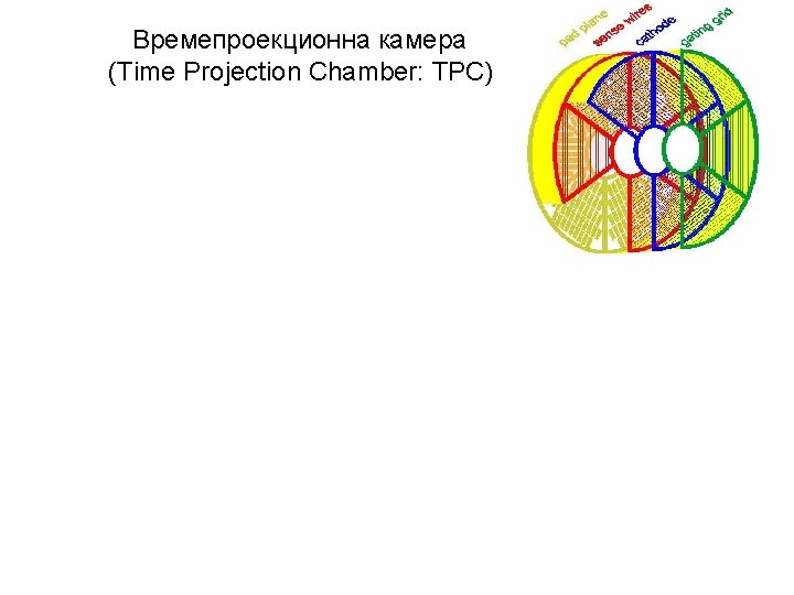
Time Projection Chamber (TPC): Gas volume with parallel E and B Field. B for momentum measurement. Positive effect: Diffusion is strongly reduced by E//B (up to a factor 5). Drift Fields 100 -400 V/cm. Drift times 10 -100 s. Distance up to 2. 5 m ! gas volume B drift E y x z charged track Wire Chamber to detect the tracks W. Riegler/CERN 39
STAR TPC (BNL) Event display of a Au Au collision at CM energy of 130 Ge. V/n. Typically around 200 tracks per event. Great advantage of a TPC: The only material that is in the way of the particles is gas very low multiple scattering very good momentum resolution down to low momenta ! 3/12/2021 W. Riegler, Particle 41
ALICE TPC: Parameters • • • Largest TPC: – Length 5 m – Diameter 5 m – Volume 88 m 3 – Detector area 32 m 2 – Channels ~570 000 High Voltage: – Cathode -100 k. V Material X 0 – Cylinder from composite materials from airplane industry (X 0= ~3%) W. Riegler/CERN • • Gas Ne/ CO 2 90/10% Field 400 V/cm Gas gain >104 Position resolution = 0. 25 mm Diffusion: t= 250 m Pads inside: 4 x 7. 5 mm Pads outside: 6 x 15 mm B-field: 0. 5 T 42
First 7 Te. V Collisions in the ALICE TPC in March 2010 !
Detectors based on registration of excited atoms Scintillators 45
Scintillators
Photomultipliers