Electricity Magnetism Part III Magnetism Table of Contents

Electricity & Magnetism Part III – Magnetism

Table of Contents Oersted’s Discovery & Current-Induced Magnetic Fields Magnetic Force JJ Thomson and the Charge-to-Mass Ratio of the Electron Mass Spectrometers

Electricity & Magnetism Prior to 1820, electricity & magnetism were thought to be unrelated phenomena. On April 21, 1820, Hans Christian Oersted happened to place a compass next to a current-carrying wire in the middle of a lecture. He noticed the needle deflect perpendicular to the wire, but only while the current was running. Thus it was discovered that electrical current induces magnetic fields! Indeed we now know that all magnetic fields are caused by moving charges! In the case of electromagnets, this is obvious; in the case of permanent magnetics (like those holding coupons to your refrigerator), the current is in the form of electrons orbiting atoms in aligned “domains”.
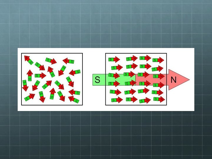

Electricity v. Magnetism Like electricity, magnetic forces can either attract or repel. Thus, like electricity, there must be two types of agents which cause magnetic force. We call these agents “poles” and we label them “north” and “south” Unlike electrical charges, you cannot isolate magnetic poles. They always come in pairs.

Current-Induced Magnetic Fields The magnetic field lines around a current-carrying conductor form concentric circles, centered on the wire. The direction of the field lines can be determined using this right-hand-rule: With your hand in a “thumbs -up” configuration, if the thumb is pointing in the direction of current, then the curling fingers indicate the direction of the magnetic field.

Magnetic Field Diagrams To draw magnetic field diagrams, we need symbols which indicate the 3 -D nature of magnetic fields. Let X’s represent a magnetic field pointing away from you and dots (or dots with circles around them) represent a magnetic field pointing toward you. X X X

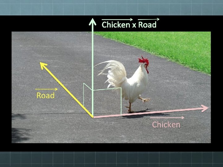
Magnetic Force Not only do currents induce magnetic fields, but the relationship goes the other way - Magnetic fields can exert force on moving charges: Fmag = qv. B(sin θ) Or, in the language of vector mathematics: Fmag = q (v × B) where: B = magnetic field strength (unit: tesla T) q = charge of particle (in coulombs) v = speed of the particle (in m/s) θ = the angle between the velocity and magnetic field vectors v and B.
 Fmag")
A few things to note about magnetic force Fmag = qv. B(sin θ) Fmag = q (v × B) Magnetic force F = 0 when v = 0. Magnetic fields exert force only on moving charges. Magnetic force F is maximized when θ = 90°, i. e. when velocity is perpendicular to the magnetic field. Magnetic force F = 0 when θ = 0° or 180°, i. e. when v || B Since force F is the cross product of velocity and magnetic field, it must be perpendicular to both!

Right Hand Rule for Magnetic Force

In what direction would the current feel a force? X X X X X X X Answer: Up, along the screen.

Two parallel wires carry current in the same direction. In what direction, if any, do they feel a force due to each other?

Two parallel wires carry current in the same direction. In what direction, if any, do they feel a force due to each other? Let’s consider the left wire.

Two parallel wires carry current in the same direction. In what direction, if any, do they feel a force due to each other? Let’s consider the left wire. X X X X X X X X X X Here’s the magnetic field it induces.

Two parallel wires carry current in the same direction. In what direction, if any, do they feel a force due to each other? Let’s consider the left wire. X X X X X X X X X X Here’s the magnetic field it induces.

Two parallel wires carry current in the same direction. In what direction, if any, do they feel a force due to each other? Let’s consider the left wire. Now consider the right wire. X X X X X X X X X X Here’s the magnetic field it induces. It’s occupying space where the magnetic field is pointing into the screen.

Two parallel wires carry current in the same direction. In what direction, if any, do they feel a force due to each other? Let’s consider the left wire. Now consider the right wire. X X X X X FX X X X X X Here’s the magnetic field it induces. It’s occupying space where the magnetic field is pointing into the screen. Therefore it feels a force F to the left.

Two parallel wires carry current in the same direction. In what direction, if any, do they feel a force due to each other? Similarly, if we consider the left wire occupying the field induced by the right wire, we see it is pulled to the right. X X X X X F X X X X X

Two parallel wires carry current in the same direction. In what direction, if any, do they feel a force due to each other? Similarly, if we consider the left wire occupying the field induced by the right wire, we see it is pulled to the right. Thus we see that there is a force of attraction between the wires here. X X X X X F X X X X X

An electron is injected into a magnetic field as shown below. What shape path will it follow? X X X X X X X X X X X

An electron is injected into a magnetic field as shown below. What shape path will it follow? X X X X X X X X X X X Answer: Circular! Force F is (and thus acceleration a ) is continuously perpendicular to velocity v. Fmag is a centripetal force! (Note: when applying the right-hand rule, initially point thumb left since we adhere to the definition of conventional current as the direction of positive flow. )

Measuring the Charge-to. Mass Ratio of an Electron Cambridge, 1897 – JJ Thomson measured q/m for an electron.

Thomson’s experimental set-up: ++++++ - + ---------

Thomson’s experimental set-up: ++++++ - + --------- Glass vacuum tube with fluorescent coating

Thomson’s experimental set-up: ++++++ - + --------Cathode Anode Glass vacuum tube with fluorescent coating

Thomson’s experimental set-up: ++++++ - + --------Cathode Anode Second set of charged parallel plates Glass vacuum tube with fluorescent coating

Thomson’s experimental set-up: Glass vacuum tube with fluorescent coating ++++++ - + --------Cathode Anode Second set of charged parallel plates Unpictured, there are external magnets outside the vacuum tube here.

Thomson’s experimental set-up: ++++++ - + --------Hydrogen gas is injected here, between the charged cathode and anode. The electric field is strong enough to rip electrons from protons. The protons crash into the negatively charged cathode, but some of the electrons emerge through a hole in the anode as a beam (a so-called “cathode ray”).

Thomson’s experimental set-up: ++++++ - + --------When the electron beam passes between the second set of parallel plates, it feels an upward electrical force due to the plates’ charge.

Thomson’s experimental set-up: ++++++ - + X X X --------But there is also a magnetic field here due to (unpictured) magnets outside the vacuum tube. The electron beam feels a downward force due to this magnetic field.

Thomson’s experimental set-up: ++++++ - + X X X --------- A B C If the beam strikes Point A, FElectric > Fmagnetic. If the beam strikes Point B, FElectric = Fmagnetic. If the beam strikes Point C, FElectric < Fmagnetic.

Measuring Beam Velocity Thomson adjusted the strength of the electric and magnetic fields influencing the beam until no deflection occurred. At this point, he knew FE = FB But FE = Eq and FB = Bqv, so when no deflection occurred, Eq = Bqv. Cancel the q’s and solve for v and you get a formula for the beam’s velocity: v = E/B (Note: this formula is not a law of physics and always true the way, say, F = ma is. This relationship only holds for the case where no deflection occurs. )

Once he knew the beam’s velocity, Thomson shut down the E-field and let the B-field control the beam’s path. Recall, a magnetic field steers charges into a circular path. Thus magnetic force is a centripetal force here: FB = Fcent Bqv = mv 2/r Solve for q/m: q / = v/ m Br Charge-to-Mass Ratio for an electron All measurable

Mass of an Electron Thomson found q/m = 1. 759 x 1011 C/kg for an electron (1897) Twelve years later, Millikan determined q = 1. 602 x 10 -19 C (Oil drop experiment, 1909) So the mass of an electron is: m = q/(q/m) = 9. 107 x 10 -31 kg

Mass of a Proton? Would this technique work to measure charge-tomass ratio for a proton? If so, how would you alter the experimental set-up? Answer: Sure! Just switch the initial anode and cathode!

Thomson’s experimental set-up: ++++++ - + Electron beam --------Cathode Anode

Thomson’s experimental set-up: ++++++ + Proton beam --------Anode Cathode Using this set-up, Thomson found mproton = 1. 6 x 10 -27 kg.

Thomson then went further, injecting neon gas, rather than hydrogen, into his apparatus. When he did this, he observed not one, but two deflection spots! How could this happen? How could neon ions have different charge-to-mass ratios if they were ionized the same as each other? Answer: Neon has two different common stable isotopes! Same number of protons but different number of neutrons!

Similar to Thomson’s apparatus, a mass spectrometer is a device for measuring the masses of, and relative abundances of, different isotopes. Positive ion beam Voltage source supplying energy to the beam ---- V ++++ Path of heavier isotope Detector Path of lighter isotope

Which particle is the most massive?

Does the same math Thomson used work for the mass spectrometer? Not quite – There’s no 2 nd pair of parallel plates steering the beam in order to help you find beam velocity v. Instead, let’s use energy considerations to find velocity v. Since each ion begins from rest, the work done by the accelerating electric field will equal the final kinetic energy of the ion: W = K. Recall that voltage is defined as V = W/q and K = ½ mv 2. Thus Vq = ½ mv 2 Solve for velocity: v = [2 q. V/m]1/2
![Thomson found q/m = v/Br If v = [2 q. V/m]1/2, then q/m =](http://slidetodoc.com/presentation_image_h2/3ef79caf134d2ea3108abc9da1a59cb1/image-43.jpg "Thomson found q/m = v/Br If v = [2 q. V/m]1/2, then q/m =")
Thomson found q/m = v/Br If v = [2 q. V/m]1/2, then q/m = [2 q. V/m]1/2/Br Square both sides: (q/m)2 = [2 q. V/m]/B 2 r 2 Cancel one power of q/m to get the charge-to-mass ratio formula for a mass spectrometer: q/m = (2 V)/(B 2 r 2) Note: Be very careful! Both formulae for q/m have the same letters! Remember: Little v = velocity; Big V = voltage!
- Slides: 43