Electricity Careers Electricity Basics Learning Intention To learn

Electricity Careers

Electricity Basics

Learning Intention: To learn the basics of electricity, including electric fields, ac/dc, circuit symbols and the key quantities involved. Success Criteria: An understanding of electricity basics will be used to complete an investigation into Ohm’s Law, and also to explore series and parallel circuits.

Circuit Symbols

Circuit Symbols There a host of different circuit symbols that you will need for the electricity unit. These are the ones required now! A V Ammeter Voltmeter Resistor Variable Resistor Cell Battery Fuse Now, copy the symbols into your workbook. Lamp Switch

Electric Fields

Electric Fields In an electric field, a charge experiences a force. Electric fields exist around charged particles and also between charged plates. Electric fields can be shown using electric field patterns. The field lines show what would happen to a POSITIVE test charge placed in the field. The separation of the field lines indicates the strength of the field.

Isolated Positive Charge For example; a positive test charge placed in the field of another positive charge would be REPELLED along the field line. + Now, look at the following examples and copy them into your workbook, using a ruler!

Isolated Positive Charge +

Isolated Negative Charge -

Two Equal but Opposite Charges + -

Charged Plates + + - This is an example of a uniform field – all of the field lines are parallel and equally spaced.

Quantities and Definitions

Electricity Quantities - Charge The following quantities are essential for understanding electricity: Charge, Q. Measured in Coulombs, C. In a circuit, we consider the charges which move to be electrons. Challenge – the charge of an electron is 1. 6 x 10 -19 C. How many electrons are there in 1 C? Attempt to calculate this in your workbook.

Electricity Quantities - Charge: 6. 25 x 1018 electrons 1 Coulomb So many electrons move around circuits that it isn’t practical to use them in calculations. We group them into Coulombs.

Electricity Quantities - Current In a circuit, the charges is made to move. This movement of charge is called Current, I. Current is defined as the number of coulombs of charge that pass a point in one second. Current is measured in Amperes (A).

Electricity Quantities - Voltage When electrons pass through a battery or supply they are given electrical energy. Voltage is defined as the number of joules of energy given to each coulomb of charge. Voltage is measured in Volts (V).

4 V Voltage Supply + Represents 1 J of Energy - A voltage supply of 4 V means that 4 J of energy are given to each coulomb of charge.

Electricity Quantities - Voltage When electrons pass through a component, work is done. Some of the energy of the electrons is transferred to the component. This causes a difference in energy across the component, which is known as an electrical potential difference.

Electricity Quantities - Resistance is defined as the opposition to current. Any component which converts electrical energy to another type will have a resistance. Resistance is measured in Ohms (Ω).

When light bulbs resist current the electrical energy is converted to light.

Electricity Quantities - Resistance A variable resistor has a resistance that can be changed, usually by turning a dial. These are used in dimmer switches.

Using a Multimeter

Using a Multimeter Current is measured using an ammeter. An ammeter must be connected in series. A +

Using a Multimeter Voltage is measured using an voltmeter. A voltmeter must be connected in parallel. The voltmeter will measure the difference in potential before and after the component, and this difference is what it displays. V +

Using a Multimeter Resistance is measured using an ohmmeter. An ohmmeter must be connected in parallel. There is no need to use a supply when measuring resistance. Ω

Using a Multimeter In physics, we use multimeters to measure voltage, current and resistance. In general, the multimeters that we use will look similar to the one below, although there may be slight variations. Voltage (d. c. ) Resistance Voltage (a. c. ) Current (d. c. ) Large currents (d. c. ) Terminals for wires

Using a Multimeter Regardless of which quantity we are measuring, there will always be a wire connected to COM (or GND). ‘COM’ terminal.

The placement of the other wire will depend on what quantity we are measuring: For large currents, select ‘ 10 A’. Dial set to ’ 10 A’. Wire put in ‘ 10 ADC’ terminal.

For d. c. voltage: Dial set to d. c. voltage. Wire put in ‘VΩma’ terminal.

For d. c. current: Dial set to d. c. current. Wire put in ‘VΩma’ terminal.

For resistance: Dial set to resistance. Wire put in ‘VΩma’ terminal.

Using a Multimeter Remember: even when using a multimeter, you must connect the meter into circuits correctly: Current: Series Voltage: Parallel Resistance: Parallel

Q = It

Current is defined as the number of coulombs of charge that pass a point in one second. From this definition, the following equation can be derived. Q = It Charge (C) Time (s) Current (A)

Example Now, work through this example as a class, completing the solution in your workbook: Example: 40 C of charge pass through a bulb in 50 s. Calculate the current in the circuit. Now, solve the examples from your workbook in your classwork jotter showing full working for each one.

Alternating and Direct Current

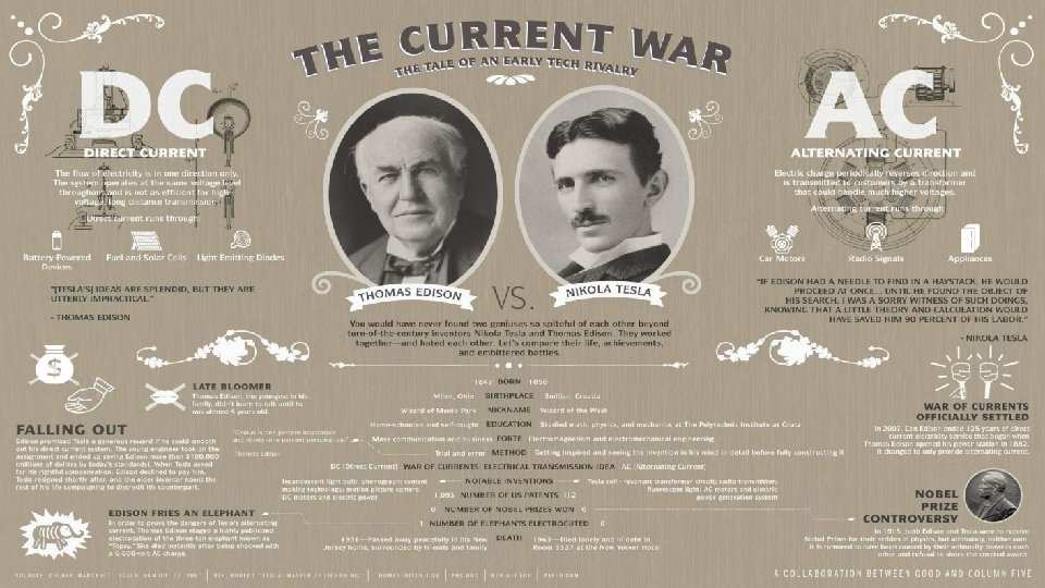
Click on the image above to see a video about the War of the Currents between Thomas Edison and Nikola Tesla…

Direct Current In a circuit with a battery or cells, the current travels in the same direction at all times. This is called direct current (d. c. ). Oscilloscope Trace:
. This signal constantly")
Alternating Current The mains supply provides alternating current (a. c. ). This signal constantly changes in value from positive to negative; in other words, it changes direction. Oscilloscope Trace:

Alternating Current Notes: 1. The quoted value of an a. c. voltage is LESS than the peak value. 2. A d. c. supply and an a. c. supply of the same quoted value will supply the same power to a given resistor. 3. The quoted value of the mains supply is 230 V. The peak value is around 325 V. 4. The frequency of the mains supply is 50 Hertz.

Summary

ELECTRICITY BASICS Circuit Symbols: A V Ammeter Voltmeter Variable Resistor A - Cell Battery Fuse Switch V Ω - + Lamp + An ammeter must be connected in SERIES. A voltmeter must be connected in PARALLEL. An ohmmeter must be connected in PARALLEL.

ELECTRICITY BASICS Electric Fields In an electric field, a charge experiences a force. Electric fields can be shown using electric field patterns. The field lines show what would happen to a POSITIVE test charge placed in the field. + Isolated Positive Charge Isolated Negative Charge + - Two Equal but Opposite Charges + + Charged Plates

ELECTRICITY BASICS Quantity Abbreviation Unit Abbreviation Definition Current I Amps A The amount of charge flowing past a point in 1 second. Voltage V Volts V The amount of energy given to each coulomb of charge. Charge Q Coulombs C NA Resistance R Ohms Ω Something which opposes current.
 Time (s) Current (A)")
ELECTRICITY BASICS Q = It Charge (C) Time (s) Current (A)

ELECTRICITY BASICS Direct Current. Batteries provide a direct current. Oscilloscope trace: Voltage Time Alternating Current. The mains supply provides an alternating current, with a quoted value of 230 V and a frequency of 50 Hz. Oscilloscope trace: Voltage Quoted Value Time

ELECTRICITY BASICS • Direct Current; the current travels in the same direction at all times. Batteries provide a direct current. • Oscilloscope trace: Voltage Time Alternating Current; the current constantly changes in value from positive to negative; in other words, it changes direction. The mains supply provides an alternating current, with a quoted value of 230 V and a frequency of 50 Hz. Oscilloscope trace: Voltage Quoted Value Time

Now, use the space in your workbook to produce a summary of electricity basics. You may wish to produce concise bullet points, or draw a mind-map, or use any other useful revision technique.
- Slides: 50