ELECTRICAL PROPERTIES Introduction Dielectric strength Dielectric constant Dissipation


- Slides: 60

ELECTRICAL PROPERTIES

• Introduction • Dielectric strength • Dielectric constant • Dissipation and power factor • Volume and surface resistivity • Arc resistance • Comparative tracking index • Static & Antistatic charges • Conductive polymers Corporate Training & Planning 2

INTRODUCTION The unbeatable combination of such characteristics as ease of fabrication, low cost, light weight, and excellent insulation properties have made plastics one of the most desirable materials for electrical applications. The majority of applications involving plastics are insulation related, plastics can be made to conduct electricity by simply modifying the base material with proper additives such as carbon black. The advent of new high-performance engineering materials has made it possible that plastics can now be used in extreme temperatures, chemicals, moisture, and stresses. Corporate Training & Planning 3

GENERAL CONCEPT ABOUT INSULATING MATERIALS § Insulating materials are those which provides high resistance to electrical current flow. § The majority of insulators are organic in nature, having covalent linkages. § The primary function of plastics in electrical application has been that of insulator. § The specific choice of an insulation material is usually determined by its application. § Now a days plastic materials like PP, PE, PVC, epoxy, PC, Floro polymers are a few amongst the long life of polymers which have wide range of applications in this industries as insulators due to their good mechanical properties and easy fabrication. § Typical electrical application of plastics material includes; plastic coated wires, terminal connectors, industrial and household plugs. Switches and printed circuit boards. Corporate Training & Planning 4

REQUIREMENT OF AN INSULATOR Ø High insulation resistance Ø Good Resistance to environmental factors Ø Good arc resistance Ø Mechanically strong. Ø High dielectric strength. Corporate Training & Planning 5

DIELECTRIC STRENGTH Definition : • The dielectric strength of an insulating material is defined as the maximum voltage required to produce a dielectric breakdown. • The dielectric strength of an insulating material is the voltage gradient at which electric failure or breakdown occurs as continuous arc. • Dielectric strength is expressed in voltage per unit of thickness such as V/mm. Corporate Training & Planning 6

DIELECTRIC STRENGTH SIGNIFICANCE This test is an indication of the electrical strength of a material as an insulator. The dielectric strength of an electrical insulating material is a property of interest for any application where an electrical field will be present. In many cases the dielectric strength of a material will be the determining factor in the design of the apparatus in which it is to be used. TEST METHODS : ASTM D-149 / IEC 243 – 1 / BS 2782 / BS 6564 SAMPLE DETAILS & CONDITIONING The recommended specimen type for this test is a 100 mm plaque or larger. Any specimen thickness can be used, however the most common thickness is between 0. 8 or 3. 2 mm The test sample is Conditioned in standard laboratory atmosphere is 23 ± 2°C , 50± 5 % RH. Corporate Training & Planning 7

DIELECTRIC STRENGTH EQUIPMENT DETAILS: The instrument used for this test consists of the following : o Voltage source o Voltage measurement device (Bridge) o Electrodes o Test Chamber (Shielding) Corporate Training & Planning 8

DIELECTRIC STRENGTH TEST PROCEDURE: • It is insured that the main supply to the equipment is turned off. • The test chamber is opened. The Specimen is placed in the form of sheets or plates having parallel plane surfaces and are of a size sufficient to prevent flashing over , after conditioning , between heavy cylindrical brass electrodes, which carry electrical current during the test. • The main supply to the equipment is switch on. The voltmeter must show zero reading. • The voltage is raised by regulator slowly till the flashover occurs. • The voltage at flashover is noted which is the breakdown voltage Corporate Training & Planning 9

DIELECTRIC STRENGTH OBSERVATION, CALCULATION & RESULT : For each sample thickness is measured & the breakdown voltage is noted. The breakdown voltage divided by the thickness gives the value of Di electric strength. The Dielectric value is expressed in Volt/mm. Corporate Training & Planning 10

DIELECTRIC STRENGTH FACTORS INFLUENCING: • • Specimen thickness Temperature Humidity Electrodes Time Mechanical Stress Processing Corporate Training & Planning 11

DIELECTRIC STRENGTH SAFETY PRECAUTIONS : • As the equipment works on high voltage an independent earthing system must be provided to the equipment. • The test chamber must not be opened when test is in progress. • Insulating gloves must be used while using equipment. • Equipment must be installed with proper over load and voltage protection system. • Appropriate exhaust system must be available. Corporate Training & Planning 12

DIELECTRIC STRENGTH CASE STUDY : Effect of crystallinity & temperature on Dielectric strength Corporate Training & Planning 13

DIELECTRIC STRENGTH OF SOME PLASTICS Plastics Dielectric strength (V/mil) Rigid PVC 800 - 1400 Thermoplastic Polyester 600 - 750 Polypropylene 650 High Impact Polystyrene 650 Nylons 350 - 560 GP Polystyrene 500 Acetals (Delrin) 500 PTFE (Teflon) 500 Polyethylene (PE) 480 Polycarbonate 450 ABS 415 Phenolics 240 - 340 Corporate Training & Planning 14

DIELECTRIC CONSTANT (PERMITIVITY) DEFINITION : • The dielectric constant of an insulating material is defined as the ratio of the charge stored in an insulating material placed between two metallic plates to the charge that can be stored when the insulating material is replaced by air or vacuum. • Dielectric constant is used to determine the ability of an insulator to store electrical energy. Corporate Training & Planning 15

DIELECTRIC CONSTANT (PERMITIVITY) SIGNIFICANCE When a material is to be use in electric application where high capacitance is needed, a higher dielectric constant is required. TEST METHODS ASTM D-150/ IEC 250 SAMPLE DETAILS & CONDITIONING It must be larger than 50 mm circular electrodes used for the measurement. The specimen allowed to remain the standard laboratory conditions of 23± 2°C and 50 ± 2% RH for a period of at least 16 hours immediately prior to test. Corporate Training & Planning 16

DIELECTRIC CONSTANT (PERMITIVITY) EQUIPMENT / INSTRUMENT DETAILS: The equipment for measurement of dielectric constant is nothing but is an equipment used to measure the capacitance. Corporate Training & Planning 17

DIELECTRIC CONSTANT (PERMITIVITY) TEST PROCEDURE : • Methods for measurement of capacitance can be done by three methods: 1. Null method 2. Resonance method 3. Deflection method • The test specimen is placed between the two electrodes and the capacitance is measured. Next, the test specimen is replaced by air and the capacitance value is again measured. Corporate Training & Planning 18

DIELECTRIC CONSTANT (PERMITIVITY) OBSERVATION , CALCULATION & RESULT : 1. The Capacitance , material as dielectric (C 1) is noted. 2. The Capacitance, air or vacuum as dielectric (C 2) is noted 3. Dielectric Constant is calculated by formula (C 1/C 2) Corporate Training & Planning 19

DIELECTRIC CONSTANT (PERMITIVITY) FACTORS INFLUENCING: Ø Frequency Ø Voltage Ø Temperature Ø Humidity Ø Water Immersion Ø Weathering Ø Deterioration Corporate Training & Planning 20

DIELECTRIC CONSTANT (PERMITIVITY) SAFETY PRECAUTIONS: • The test apparatus & all associated equipment electrically connected to it must be solidly grounded. • When using the solid electrodes, the air gap between electrodes must be avoided, which may affect the result. • The plate spacing must be adjusted accurately to a value suitable to the specimen to be tested. For low loss materials in particular the plate spacing and the specimen thickness should be such that the specimen will occupy not less than about 80 % of the electrode gap. • Insulating gloves must be used while using equipment. • Equipment must be installed with proper over load and voltage protection system. Corporate Training & Planning 21

DIELECTRIC CONSTANT (PERMITIVITY) CASE STUDY : Effect of temperature on Dielectric constant (loss factor) Corporate Training & Planning 22

DIELECTRIC CONSTANT OF SOME PLASTICS DIELECTRIC CONSTANT Melamines 5. 2 – 7. 9 Phenolics 4. 0 – 7. 0 Nylon 30% Gf 3. 5 – 5. 4 Epoxies 4. 3 – 5. 1 High impact polystyrene 2. 0 -4. 0 Nylon 3. 5 – 3. 8 Acetals 3. 7 Polycarbonate 30% GF 3. 48 Polysulfone 30% GF 3. 4 Thermoplastic Polyester 3. 2 ABS 3. 2 Corporate Training & Planning 23

DISSIPATION FACTOR & POWER FACTOR DEFINITION : DISSIPATION FACTOR: The measure of power loss dissipated as heat due to the build-up and collapse of the dielectric field within the insulation in an A. C. circuit, especially at high frequencies, is termed as dissipation factor. It is often known as tan δ or loss tangent. POWER FACTOR : Power factor is the ratio of power loss in watts dissipated in the material to the product of the r. m. s voltage applied and the r. m. s current passing through the material. It is equal the cosine of the phase angle i. e cos θ. Corporate Training & Planning 24

DISSIPATION FACTOR & POWER FACTOR SIGNIFICANCE • In case of electrical insulation & as capacitor dielectric , the dissipation factor (ac loss) must be small in order to reduce the heating of the material and to minimise its effect on the rest of the network. • The dissipation factor is a measure of the electrical energy lost as heat in the material serving as the dielectric substance of capacitors where the electric field is applied perpendicular to the plane of application. TEST METHODS : ASTM D 1531 / ASTM D 1673 EQUIPMENT DETAILS & TEST PROCEDURE For determination of dissipation factor & power factor the value of parallel capacitance and equivalent parallel resistance has to be measured. These values can be measured in same way as explained for measurement of capacitor in dielectric test. Corporate Training & Planning 25

DISSIPATION FACTOR & POWER FACTOR OBSERVATION, CALCULATION & RESULT : 1. The Parallel Capacitance (Cp) is noted. 2. The Equivalent Parallel resistance (Rp) is noted 3. Dissipation factor is calculated by following formula D=1/w. Cp. Rp Corporate Training & Planning 26

DISSIPATION FACTOR OF SOME PLASTICS DISSIPATION FACTOR (AT 1 MHZ) Low density polyethylene > 0. 0005 High density polyethylene > 0. 0005 Acetal 0. 0048 Polypropylene (isotactic) 0. 0005 -0. 0018 PVC (unplasticized) 0. 006 -0. 019 ABS 0. 007 -0. 015 Polycarbonate 0. 01 Polmethylmethacrylate 0. 02 -0. 03 Polyethyleneteraphthalate 0. 0208 Corporate Training & Planning 27

SURFACE & VOLUME RESISTIVITY DEFINITION : SURFACE RESISTIVITY : • It is defined as the ability of material to resist the leakage along the surface of the insulator. • The surface resistivity is a measure of the resistance of the material to a surface flow of current. VOLUME RESISTIVITY : • It is defined as the ratio of the potential gradient parallel to the current in the material to the current density. • The volume resistivity is a measure of the resistance of the material in terms of its volume. Corporate Training & Planning 28

SURFACE & VOLUME RESISTIVITY SIGNIFICANCE The insulating material should have resistance as high as possible with good mechanical, chemical and heat resisting properties. TEST METHODS : ASTM D-257 / ASTM D 2305 / BS 2782 / BS 3815/ ISO 1325 SAMPLE DETAILS & CONDITIONING : The specimen will be a sheet of material, 1 to 3 mm thick, at least 10 mm large than the diameter of the unguarded electrode. The test sample is Conditioned at 23± 2°C and a relative humidity of 50 ± 5% for 24 hours. Corporate Training & Planning 29

SURFACE & VOLUME RESISTIVITY EQUIPMENT DETAILS: For most material the volume resistivity will be greater than 109 Ω cm and the measured resistivity using the electrodes will be about 109 Ω. Measurement in this range will require the use of an “Megaohmmeter” drawing “Bias” current less than 10 -12 A. Corporate Training & Planning 30

SURFACE & VOLUME RESISTIVITY Corporate Training & Planning 31

SURFACE & VOLUME RESISTIVITY Corporate Training & Planning 32

SURFACE & VOLUME RESISTIVITY TEST PROCEDURE: • • The specimen is prepared in accordance with the particular test procedure being employed and is then conditioned as necessary. Any necessary intimate electrodes and contacting medium are applied. It the intimate electrodes are applied by vacuum metallizing, the specimen is conditioned after application. The specimen is mounted in the specimen holder/electrode assembly and connections made to the measuring instrument. Test potential is applied via the ‘charging’ position of the instrument switch for atleast about 10% of the specified electrification time (usually about 5 seconds). • The instrument connection switch is moved to the “read” position and the range switch set to an appropriate level at least 10 seconds before reading the resistance at the specified electrification time. The time of electrification is usually 1 min. 7 the applied voltage is 500+5 Volt. The indicated resistance will not usually be constant but will steadily increase, at a rate dependent on the test material. • If necessary, the capacity of the specimen/electrode assembly is measured. Corporate Training & Planning 33

SURFACE & VOLUME RESISTIVITY OBSERVATION , CALCULATION & RESULT VOLUME RESISTIVITY 1. The Volume Resistance (Rv) is noted from the meter. 2. The Area of electrode (A) is calculated. 3. The thickness of the specimen (t) is measured. 4. Volume Resistivity is calculated by following formula ρv = Rv A/t SURFACE RESISTIVITY 1. The Surface Resistance (Rs) is noted from the meter. 2. The parameter of guard electrode (p) is calculated. 3. The gap between the electrodes (g) is measured. 4. Volume Resistivity is calculated by following formula ρs = Rs p/g Corporate Training & Planning 34

SURFACE & VOLUME RESISTIVITY FACTORS INFLUENCING: • • A small amount of impurities in a polymer can considerably change its electrical resistance. Prolong uses of an insulator may cause degradation and adversely affect the insulation resistance following the chemical charge which take place in the polymer. The resistivity of the polymer is also affected by the type and amount of additive used. The nature and geometry of electrodes. Magnitude and time of applied voltage. Test conditions i. e. temperature & humidity. Molding defects in the test specimen. Moisture content in the test specimen. Corporate Training & Planning 35

SURFACE & VOLUME RESISTIVITY SAFETY PRECAUTIONS: • The Test apparatus and all associated equipment electrically connected to it must be solidly grounded. • The electrodes must be handled carefully to avoid damage etc • Insulating gloves must be used while using equipment. • The surfaces of the specimen must be smooth & perfectly clean for getting the accurate Value. • While using the digital meters, it must be kept in switched on condition for some time before starting the test to stabilize the reading. • The equipment must not be frequently turned-on and turned-off. Corporate Training & Planning 36

SURFACE & VOLUME RESISTIVITY CASE STUDY : Effect of temperature on Resistivity Corporate Training & Planning 37

VOLUME RESISTIVITY OF SOME PLASTICS VOLUME RESISTIVITY (Ω-CM) Urea Formaldehyde 1012 - 1013 Acrylics 1014 Epoxy 1014 Polystyrene 1016 SAN 1016 ABS 5 x 10¹⁶ Polycarbonate 2 x 10¹⁶ Flexible PVC 1011 – 1015 Nylon 6, 6 1014 – 1015 Rigid PVC 1015 Polyethylene 1016 Polypropylene 1016 Thermoplastic Polyester 3 x 10¹⁶ PTFE 1018 Corporate Training & Planning 38

ARC RESISTANCE DEFINITION Arc resistance is defined as the ability of the plastic material to resist the action of a high voltage electrical arc, and is usually stated in terms of time require to form material electrically conductive. SIGNIFICANCE It is used for differentiation among silmilar materials with respect to their resistance to the action of high voltage low current to the surface of the insulation. By this action a conductive path is made due to thermal & chemical decomposition and erosion. Corporate Training & Planning 39

ARC RESISTANCE TEST METHODS : ASTM D 495 SAMPLE DETAILS & CONDITIONING • A flat surface sample with minimum 1 mm thickness is used. When testing molded parts, the arc is applied to a location deemed most significant • The specimen is warmed in a 50°C oven for about 30 minutes. Corporate Training & Planning 40

ARC RESISTANCE EQUIPMENT DETAILS: The instrument used for this test consists of the following • • Voltage generation and control device Autotransformer Voltmeter & Mill ammeter Interrupter Timer Electrodes Electrode assembly Corporate Training & Planning 41

ARC RESISTANCE TEST PROCEDURE: • It is insured that the main supply to the equipment is turned off. • The test chamber is opened. The specimen is placed in the electrode assembly and the spacing between the electrodes is checked which are generally separated by 6. 35 mm and placed in vertical position at an angle of 35° from the horizontal plane of specimen surface. • The main supply to the equipment is switched on. • The equipment is calibrated so as to apply open circuit voltage of 12. 5 KV and current is adjusted to 10 m. A. Once arc is maintained at this test condition timer is turned on. • Initially arc severity is maintained with current of 10 m. A for 1 min. At the end of each 1 min. the arc severity is increased stepwise. • The time for the formation of conductive path (failure) is recorded. Corporate Training & Planning 42

ARC RESISTANCE OBSERVATION, CALCULATION & RESULT : • The failure is characterized by carbonization of the surface, tracking, localized heating to incandescence or burning. • The total time to failure is recorded. • Arc resistance is measured in seconds to failure. Corporate Training & Planning 43

ARC RESISTANCE SAFETY PRECAUTIONS: • The test apparatus & all associated equipment electrically connected to it must be solidly grounded. • The electrodes must be cleaned in regular intervals. • Insulating gloves must be used while using equipment. • The test chamber must not be opened when test is in progress. Corporate Training & Planning 44

ARC RESISTANCE OF SOME PLASTICS ARC RESISTANCE (SEC) Low density polyethylene 135 -160 Medium/ High density polyethylene 200 -235 Polypropylene (Isotactic) 136 -185 Nylon 6 and 6, 6 140 Polystyrene 60 -100 Polycarbonate 10 -120 Acrylonitrile –butadiene-styrene (ABS) 50 -85 Poly (vinyl chloride ) (unplasticized) 60 -80 Styrene Acrylonitrile 100 -150 Polytetraflouroethylene >200 Poly (methyl methacrylate) No track Acetal (Polyoxymethylene) 129 Corporate Training & Planning 45

COMPARATIVE TRACKING INDEX DEFINITION Comparative tracking index is defined for electrical insulating materials as the numerical value of that voltage which will cause failure by tracking when the number of drops of contaminant required to cause failure is equal to 50. SIGNIFICANCE Electrical equipment may fail as a result of electrical tracking of insulating material that is exposed to various contaminating environments & surface conditions. Corporate Training & Planning 46

COMPARATIVE TRACKING INDEX TEST METHODS : ASTM D 5288 SAMPLE DETAILS Typical test specimens can be 50 mm or 100 mm diameter disks or any similar shape. Minimum thickness shall be 2. 5 mm Corporate Training & Planning 47

COMPARATIVE TRACKING INDEX EQUIPMENT DETAILS: The equipment for Comparative tracking index consists of following : • • Variable power source. Voltmeter Ammeter Current Limiting Resistor Shorting switch: Single –pole single – throw Over-current Relay Platinum Electrode Dropping apparatus Corporate Training & Planning 48

COMPARATIVE TRACKING INDEX Corporate Training & Planning 49

COMPARATIVE TRACKING INDEX TEST PROCEDURE: • It is insured that Main supply to the equipment is off. • The dropping assembly is filled with solution and set the counter at 0. • The test specimen is placed on the supporting platform so that the electrodes can be placed on the specimen. • The electrodes are positioned in such a fashion, so that the chisel edges contact the specimen at a 60° angle between electrodes and so that the chisel faces are parallel in the vertical plane and are separated by 4 ± 0. 2 mm. • The power to equipment is turned ON. Corporate Training & Planning 50

COMPARATIVE TRACKING INDEX • The power source is set to the desired voltage level. • The drop interval is regulated so that the time interval between two consecutive drops must be 30 ± 5 seconds. • The reading of no. of drops is recorded at different voltage levels such that at least two levels produce failures in less than 50 drops and two levels greater than 50 drops • A test may be repeated on a given specimen provided the electrode gap is positioned a minimum of 25 mm from any area affected by a previous test or from any edge. • Test voltage should be limited to 600 V or less. Testing at higher voltages will generate electric discharges above the surface of the specimen, which will produce erroneous results. Corporate Training & Planning 51

COMPARATIVE TRACKING INDEX OBSERVATION, CALCULATION & RESULT : • The reading of voltage & no. of drops are noted. • A graph is plotted between the number of drops of electrolyte at breakdown versus voltage. On the curve the voltage which corresponds to 50 drops is noted. This voltage is the comparative track Index (CTI) • The CTI is expressed in volts. Corporate Training & Planning 52

COMPARATIVE TRACKING INDEX SAFETY PRECAUTIONS: • The test apparatus and all associated equipment electrically connected to it must be solidly grounded. • The electrodes must be cleaned on regular intervals. • Insulating gloves must be worn while operating the equipment • The test chamber must not be opened while test is in progress • The concentration of electrolyte must be checked in regular intervals Corporate Training & Planning 53

COMPARATIVE TRACKING INDEX STATIC CHARGES AND ANTISTATIC CHARGES • Static electricity can be simply stated as an excess or deficiency of electrons on a surface. In cases where insulating material is separated from another insulator (or from a conductor), the electrostatic charges generated may become unbalanced which can leave an excess or deficit of electrons on the insulating material. • Static charges occurs when two nonconductive bodies rub or slide together or separate from one another. It is often referred to as the tribo electric effect. One of the material will result in a positive electrical charge on its surface and the other a negative charge. • A number of factors influence the polarity and size of the charge. They are cleanliness, pressure of contact, surface area and speed of rubbing or separating. Corporate Training & Planning 54

CONDUCTING POLYMERS INTRODUCTION Conducting plastics materials are those plastics which are capable of carrying the current through itself. Generally thermoplastics can be used as conductive plastics. Modification of thermoplastics by the addition of a conductive material to the resin matrix results in a product or compound having conductive properties. Corporate Training & Planning 55

CONDUCTING POLYMERS ADVANTAGES OF CONDUCTIVE PLASTICS OVER METAL CONDUCTORS: • Conductive plastics are more cost effective than metals in some applications requiring electrical conductivity. The economics of the injection moulding process is one reason for this advantage. • Another advantage is the design capability of combining several metal fabrication steps into a single moulding step with plastics. • In addition, conductive plastics offer significant performance and design advantages over metals. • Conductive plastics have superior impact resistance and non corrosiveness over metals Corporate Training & Planning 56

CONDUCTING POLYMERS TYPES OF CONDUCTIVE PLASTICS : I. The first is one which is filled with conductive filler particles, such as carbon black or metal powders. Such plastics generally have resistivities from about 107 Ωcm down to about 10 -2 Ωcm. In this range they are relatively insensitive to temperature, humidity and voltage, but if they are flexible they are sensistive to strain history. II. The second type of conductive polymers contains additives known as antistatic agents, which are organic molecules that diffuse to the surface and either dissociate to give mobile ions or are hydrophilic and collect a film of moisture on the surface. These are sometimes highly sensitive to humidity and temperature but little is known about their sensitivity to voltage and they are insensitive to strain. Corporate Training & Planning 57

CONDUCTING POLYMERS ADVANTAGES OF USING THERMOPLASTICS AS A CONDUCTIVE PLASTICS : • Light weight • Cost effectiveness • Appearance • Convenient processing and finishing Corporate Training & Planning 58

CONDUCTING POLYMERS CONDUCTIVE ADDITIVES : • Suppliers of conductive thermoplastics products uses a number of conductive additives. The examples of these conductive additives are as under: Reinforced type Additive type PAN carbon fibre Carbon black powder Pitch carbon fibre Aluminium flakes Nickel coated carbon fibre Metal powders Stainless steel fibres Organic-antistatic Aluminium fibres Metal coated glass beads Metallized glass fibres Metal coated mica Corporate Training & Planning 59

THANK YOU Corporate Training & Planning 60
 What is dielectrics
 Dielectric constant of bakelite
 Dielectric constant definition in physics
 High speed pcb material
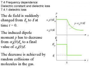
 Frequency dependence of dielectric constant
 Phase constant
 Dielectric properties of food
 Transistor power dissipation
 Velocity dependent potential and dissipation function
 Dissipation visqueuse
 Nmos inverter with enhancement load
 Disipasi daya
 Dissipation test
 Power dissipation
 Europe turbulence forecast
 Steel bar
 Ratio strength pharmacy
 How to make half strength darrows
 Express 5 ppm of iron in water in percentage strength.
 Constant pointer and pointer to constant
 Constant pointer and pointer to constant
 Constant pointer and pointer to constant
 Metals tend to be
 Rate constant and equilibrium constant
 Big k little k
 Solubility and complex ion equilibria
 Pointer constant in c
 Display the address of intval using cout and intptr.
 Potassium lithium
 Constant pressure filtration equation
 Units of gas constant
 Tyndall effect
 Properties of nerve fibres
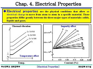
 Electrical properties of matter
 Electrical conductivity property of matter
 Properties of nerve fibre
 How electricity works
 Electrical safety introduction
 Lesson 5 introduction to electrical devices
 Introduction to electrical power systems
 Nccer introduction to electrical circuits
 Extensive properties and intensive properties
 Is smell a physical property
 Solid dielectric switch gear
 Wave propagation in lossy dielectrics
 Dielectric heating
 Langevin debye equation
 Electric displacement
 Difference between induction heating and dielectric heating
 Thermal breakdown in solid dielectrics
 Capacitor reading
 Difference between capacitor and capacitance
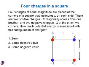
 4 charges in a square
 Ir test of transformer
 Macroscopic electric field
 Conduction and breakdown in commercial liquids
 Properties of underground cables
 Boundary conditions for perfect dielectric materials
 Difference between dielectric and conductor
 Gauss law in dielectrics
 Interlevel dielectric

