Electrical MachineI EE 2107 Dr Md Sherajul Islam


- Slides: 23
Electrical Machine-I EE 2107 Dr. Md. Sherajul Islam Associate Professor Department of Electrical and Electronics Engineering Khulna University of Engineering & Technology Khulna, Bangladesh
Transformer
Physical image of Transformer
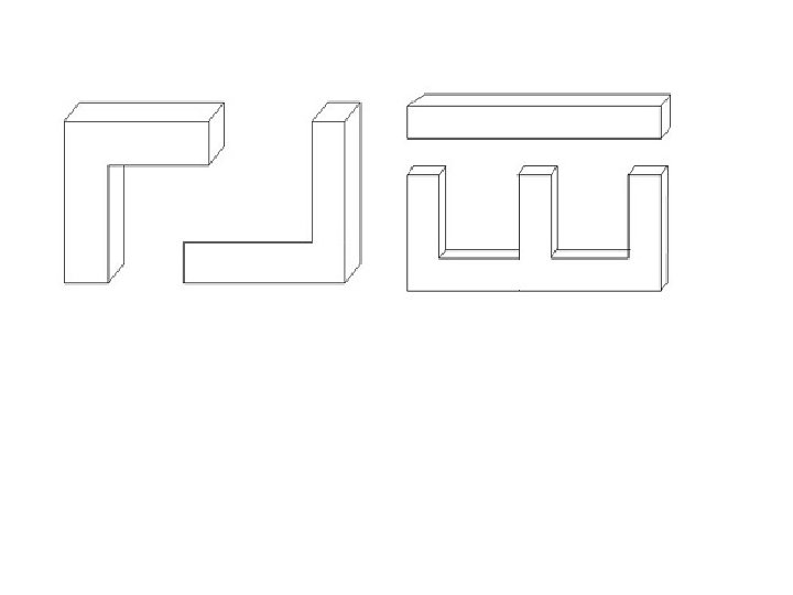
Depending upon the type of construction used: I. Core type II. Shell type
Basis for Comparison Core Type Transformer Shell Type Transformer Definition The winding surround the core. The core surround the winding. Lamination Shape The lamination is cut in the form of the Lamination are cut in the form L strips. of the long strips of E and L. Cross Section Cross-section may be square, cruciform The cross section is rectangular and three stepped in shape. Copper Require More Less Other Name Concentric Winding or Cylindrical Winding. Two More Sandwich or Disc Winding Limb Insulation Flux Three Less Magnetic Circuit Central limb carry the whole flux and side limbs carries the half of the flux. The primary and secondary winding are Primary and secondary placed on the side limbs. windings are placed on the central limb Two One Losses More Less Maintenance Easy Difficult Winding The flux is equally distributed on the side limbs of the core.
I. II. IV. Comparison of core type and shell type transformers: - Construction: - Core type transformers are much simpler in design and permit easier assembly and insulation of winding. Mechanical forces: - The forces produced between windings is proportional to the product of the currents carried by them. Very large electromagnetic forces are produced when secondary winding is short circuited. Since the windings carry currents in opposite direction, there exists a force of repulsion between them. Hence, the inner winding experiences a compressive force and outer winding experiences a tensile force. 3 In a shell type transformer, windings have greater capability of withstanding forces produced under short circuit as these windings are surrounded and supported by the core. But in a core type transformer windings have a poorer mechanical strength. Leakage reactance: - In core type transformer large space required between the high and low voltage winding, it is not possible to subdivided the winding, while, in shell type transformer the windings can be easily subdivided by using sandwich coil. So it is possible to reduce the leakage reactance of shell type transformers. Repairs: - The winding of core type transformer is completely accessible so coils can be easily inspected. And also core type transformer is easy to dismantle for repair. In shell type transformer, the coils are surrounded by core, therefore difficulty in inspection and repair of coils. Cooling: - In core type transformer windings are exposed and therefore the cooling is better in winding than core. In case of shell type transformer core is exposed therefore cooling is better than winding.
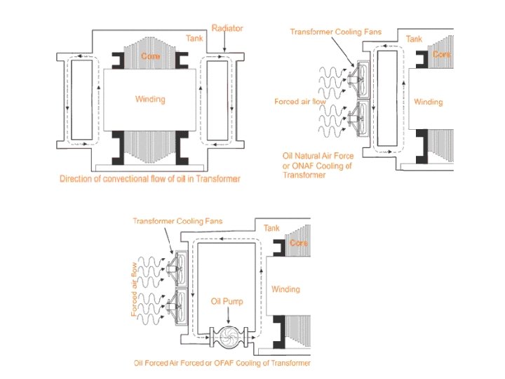
Transformer Cooling System and Methods The main source of heat generation in transformer is its copper loss or I 2 R loss. Other factors contribute heat in transformer such as hysteresis and eddy current losses In electrical power transformer we use external transformer cooling system to accelerate the dissipation rate of heat of transformer. 1. ONAN 2. ONAF 3. OFAF 4. OFWF 5. ODAF 6. ODWF
ONAN: This is the simplest transformer cooling system. The full form of ONAN is "Oil Natural Air Natural". Here natural convectional flow of hot oil is utilized for cooling. In convectional circulation of oil, the hot oil flows to the upper portion of the transformer tank and the vacant place is occupied by cold oil. This hot oil which comes to upper side, will dissipate heat in the atmosphere by natural conduction, convection and radiation in air and will become cold. In this way the oil in the transformer tank continually circulate when the transformer put into load. ONAF : Heat dissipation can obviously be increased, if dissipating surface is increased but it can be make further faster by applying forced air flow on that dissipating surface. Fans blowing air on cooling surface is employed. Forced air takes away the heat from the surface of radiator and provides better cooling than natural air. The full form of ONAF is "Oil Natural Air Forced". As the heat dissipation rate is faster and more in ONAF transformer cooling method than ONAN cooling system, electrical power transformer can be put into more load without crossing the permissible temperature limits. OFAF : In OFAF cooling system the oil is forced to circulate within the closed loop of transformer tank by means of oil pumps. OFAF means "Oil Forced Air Forced" cooling methods of transformer. The main advantage of this system is that it is compact system and for same cooling capacity OFAF occupies much less space than farmer two systems of transformer cooling. Actually in oil natural cooling system, the heat comes out from conducting part of the transformer is displaced from its position, in slower rate due to convectional flow of oil but in forced oil cooling system the heat is displaced from its origin as soon as it comes out in the oil, hence rate of cooling becomes faster
OFWF We know that ambient temperature of water is much less than the atmospheric air in same weather condition. So water may be used as better heat exchanger media than air. In OFWF cooling system of transformer, the hot oil is sent to a oil to water heat exchanger by means of oil pump and there the oil is cooled by applying sowers of cold water on the heat exchanger's oil pipes. OFWF means "Oil Forced Water Forced" cooling in transformer. ODAF or oil directed air forced cooling of transformer can be considered as the improved version of OFAF. Here forced circulation of oil directed to flow through predetermined paths in transformer winding. The cool oil entering the transformer tank from cooler or radiator is passed through the winding where gaps for oil flow or predecided oil flowing paths between insulated conductor are provided for ensuring faster rate of heat transfer. ODAF or oil directed air forced cooling of transformer is generally used in very high rating transformer. ODWF ODAF or oil directed water forced cooling of transformer is just like ODAF only difference is that here the hot oil is cooled in cooler by means of forced water instead of air. Both of these transformer cooling methods are called forced directed oil cooling of transformer.
Auto Transformer • An autotransformer has a single winding on an iron core and a part of winding is common to both the primary and secondary circuits.
Theory of Autotransformer • Winding 1 -3 - N 1 turns - pri winding • winding 2 -3 - N 2 turns - sec winding • Input current is I 1 • Output current is I 2 • Portion 1 -2 of the wdg has N 1 - N 2 turns and voltage across this portion of the winding is V 1 - V 2. The current through the common portion of the winding is I 2 - I 1. •
Theory of Autotransformer •
Output of Autotransformer •
Saving of Copper in Auto Transformer • For the same output and voltage transformation ratio, an autotransformer requires less copper than an ordinary 2 -winding transformer. • Weight of Cu required in a winding is α current X turns
Saving of Copper in Auto Transformer Two winding transformer • Weight of Cu required α (I 1 N 1 + I 2 N 2) Autotransformer • Weight of Cu required in section 1 -2 α I 1 (N 1 – N 2) • Weight of Cu required in section 2 -3 α (I 2 – I 1) N 2 • Total weight of Cu required α I 1 (N 1 – N 2) + (I 2 – I 1) N 2
Saving of Copper in Auto Transformer
Saving of Copper in Auto Transformer § Thus if K = 0. 1, the saving of Cu is only 10% but if K = 0. 9, saving of Cu is 90%. § Therefore, saving of Cu is more when K is nearer to 1.
Advantages of Autotransformers • An autotransformer requires less Cu than a two -winding transformer of similar rating. • Autotransformer operates at a higher efficiency than a two-winding transformer of similar rating. • An autotransformer has better voltage regulation than a two-winding transformer of the same rating. • An autotransformer has smaller size than a two-winding transformer of the same rating.
Advantages of Autotransformers • An autotransformer requires smaller exciting current than a two-winding transformer of the same rating. • These advantages decrease as the ratio of transformation increases. So an autotransformer has advantages only for low values of transformation ratio.
Disadvantages of Autotransformers • There is a direct connection between the primary and secondary. Therefore, the output is no longer isolated from the input. • It is not safe for stepping down a high voltage to a low voltage. • The short - circuit current is much larger than for the two -winding transformer of the same rating. • This reduces the effective resistance and reactance.
Applications of Autotransformers • Autotransformers are used to compensate for voltage drops in transmission and distribution lines. When used for this purpose, they are known as booster transformers. • Autotransformers are used for reducing the voltage supplied to a. c. motors during the starting period. • Autotransformers are used for continuous variable supply.