Electrical MachineI EE 2107 Dr Md Sherajul Islam


 Synchronous Motors. 1. Plain 2. Super (b)")


 • “Stationary” part of the motor sometimes referred to as “the windings”.")
 Squirrel Cage (b) Slip-Ring Squirrel cage")


, i. e. s =1,")


- Slides: 53
Electrical Machine-I EE 2107 Dr. Md. Sherajul Islam Assistant Professor Department of Electrical and Electronics Engineering Khulna University of Engineering & Technology Khulna, Bangladesh
Part II Induction Motor
Classification Based On Principle Of Operation: (a) Synchronous Motors. 1. Plain 2. Super (b) Asynchronous Motors. 1. Induction Motors: (a) Squirrel Cage (b) Slip-Ring (external resistance). 2. Commutator Motors: (a) Series (b) Compensated (c) Shunt (d) Repulsion (e) Repulsion-start induction (f) Repulsion induction Classification Based On Type Of Current: 1. Single Phase 2. Three Phase Classification Based On Speed Of Operation: 1. Constant Speed. 2. Variable Speed. 3. Adjustable Speed. Classification Based On Structural Features: 1. Open 2. Enclosed 3. Semi-enclosed 4. Ventilated 5. Pipe-ventilated 6. Riveted frame-eye etc. .
Physical image of Induction Motor
Terminal of Induction Motor
Internal View of Induction Motor
Internal View of Induction Motor
Cut View of an Induction Motor
Main Parts of Induction Motor
Stator (Windings) • “Stationary” part of the motor sometimes referred to as “the windings”. • Slotted cores made of thin sections of soft iron are wound with insulated copper wire to form one or more pairs of magnetic poles. Rotor • “Rotating” part of the motor. • Magnetic field from the stator induces an opposing magnetic field onto the rotor causing the rotor to “push” away from the stator field. Other parts : Assignment
There are two types of rotor winding (a) Squirrel Cage (b) Slip-Ring Squirrel cage rotor consists of copper bars, slightly longer than the rotor, which are pushed into the slots. The ends are welded to copper end rings, so that all the bars are short circuited. In small motors, the bars and end-rings are die cast in aluminum to form an integral block
A wound rotor has a 3 -phase winding, similar to the stator winding. The rotor winding terminals are connected to three slip rings which turn with the rotor. The slip rings/brushes allow external resistors to be connected in series with the winding. The external resistors are mainly used during start-up – under normal running conditions the windings short circuited externally.
Advantages of Induction Motor 1. Induction motors are simple and rugged in construction. Advantage of induction motors are that they are robust and can operate in any environmental condition 2. Induction motors are cheaper in cost due to the absence of brushes, commutators, and slip rings 3. They are maintenance free motors unlike dc motors and synchronous motors due to the absence of brushes, commutators and slip rings. 4. Induction motors can be operated in polluted and explosive environments as they do not have brushes which can cause sparks 5. 3 phase induction motors will have self starting torque unlike synchronous motors, hence no starting methods are employed unlike synchronous motor. However, single-phase induction motors does not have self starting torque, and are made to rotate using some auxiliaries. These advantages in induction motors make them more prominent in industrial and domestic applications
Disadvantages of Induction Motor 1. 3 phase induction motors have poor starting torque and high have in rush currents. Therefore these motors are not widely used for applications which require high starting torques like traction systems. 2. Induction motors always operate under lagging power factor and during light load conditions they operate at very worst power factor (0. 2 to 0. 4 lagging). Some of the disadvantages of poor power are increase in I 2 R losses in the system, reduction in the efficiency of the system. 3. One of the main disadvantages of induction motors is that speed control of induction motors are difficult. Hence for fine speed control applications dc motors are used in place of induction motors.
Applications of Induction Motor Squirrel cage induction motors are simple and rugged in construction, are relatively cheap and require little maintenance. Hence, squirrel cage induction motors are preferred in most of the industrial applications such as in Lathes Drilling machines Agricultural and industrial pumps Industrial drives. Slip ring induction motors when compared to squirrel cage motors have high starting torque, smooth acceleration under heavy loads, adjustable speed and good running characteristics. Lifts Cranes Conveyors , etc. ,
P 50 Hz 60 Hz 2 3000 3600 4 1500 1800 6 1000 1200 8 750 900 10 600 720 12 500 600
Induction motor speed • At what speed will the IM run? – Can the IM run at the synchronous speed, why? – If rotor runs at the synchronous speed, which is the same speed of the rotating magnetic field, then the rotor will appear stationary to the rotating magnetic field and the rotating magnetic field will not cut the rotor. So, no induced current will flow in the rotor and no rotor magnetic flux will be produced so no torque is generated and the rotor speed will fall below the synchronous speed – When the speed falls, the rotating magnetic field will cut the rotor windings and a torque is produced
Induction motor speed • So, the IM will always run at a speed lower than the synchronous speed • The difference between the motor speed and the synchronous speed is called the Slip Where nslip= slip speed nsync= speed of the magnetic field nm = mechanical shaft speed of the motor
The Slip Where s is the slip Notice that : if the rotor runs at synchronous speed s = 0 if the rotor is stationary s = 1 Slip may be expressed as a percentage by multiplying the above eq. by 100, notice that the slip is a ratio and doesn’t have units
Frequency of rotor current • The frequency of the voltage induced in the rotor is given by Where fr = the rotor frequency (Hz) P = number of stator poles n = slip speed (rpm)
Frequency • What would be the frequency of the rotor’s induced voltage at any speed nm? • When the rotor is blocked (s=1) , the frequency of the induced voltage is equal to the supply frequency • On the other hand, if the rotor runs at synchronous speed (s = 0), the frequency will be zero
Equivalent Circuit • The induction motor is similar to the transformer with the exception that its secondary windings are free to rotate As we noticed in the transformer, it is easier if we can combine these two circuits in one circuit but there are some difficulties
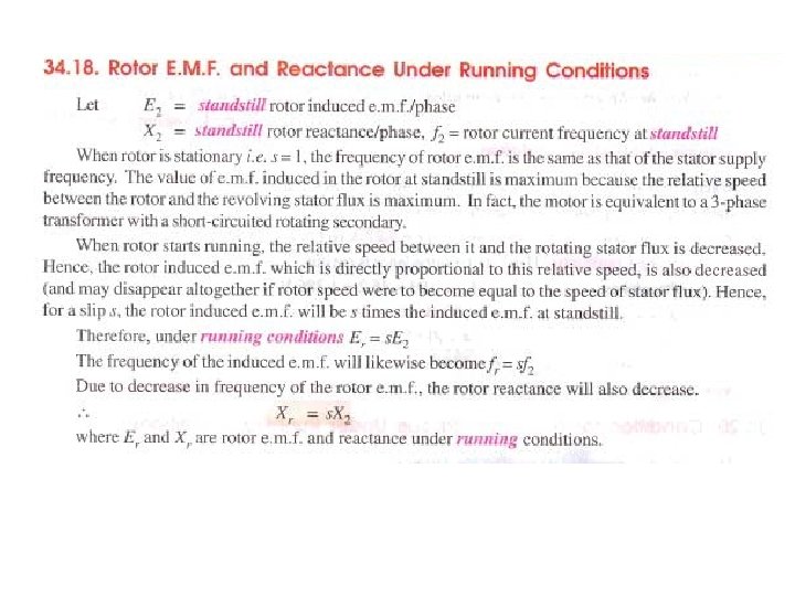
Equivalent Circuit • When the rotor is locked (or blocked), i. e. s =1, the largest voltage and rotor frequency are induced in the rotor, Why? • On the other side, if the rotor rotates at synchronous speed, i. e. s = 0, the induced voltage and frequency in the rotor will be equal to zero, Why? Where ER 0 is the largest value of the rotor’s induced voltage obtained at s = 1(loacked rotor)
Equivalent Circuit • The same is true for the frequency, i. e. • It is known that • So, as the frequency of the induced voltage in the rotor changes, the reactance of the rotor circuit also changes Where Xr 0 is the rotor reactance at the supply frequency (at blocked rotor)
Equivalent Circuit • Then, we can draw the rotor equivalent circuit as follows Where ER is the induced voltage in the rotor and RR is the rotor resistance
Equivalent Circuit • Now we can calculate the rotor current as • Dividing both the numerator and denominator by s so nothing changes we get Where ER 0 is the induced voltage and XR 0 is the rotor reactance at blocked rotor condition (s = 1)
Equivalent Circuit • Now we can have the rotor equivalent circuit
Equivalent Circuit • Now as we managed to solve the induced voltage and different frequency problems, we can combine the stator and rotor circuits in one equivalent circuit Where
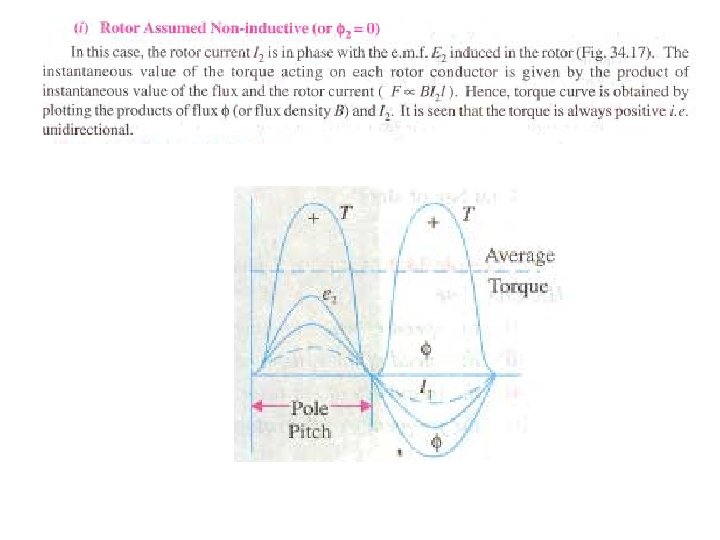
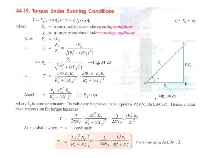
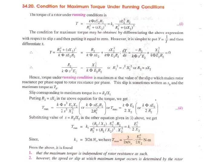
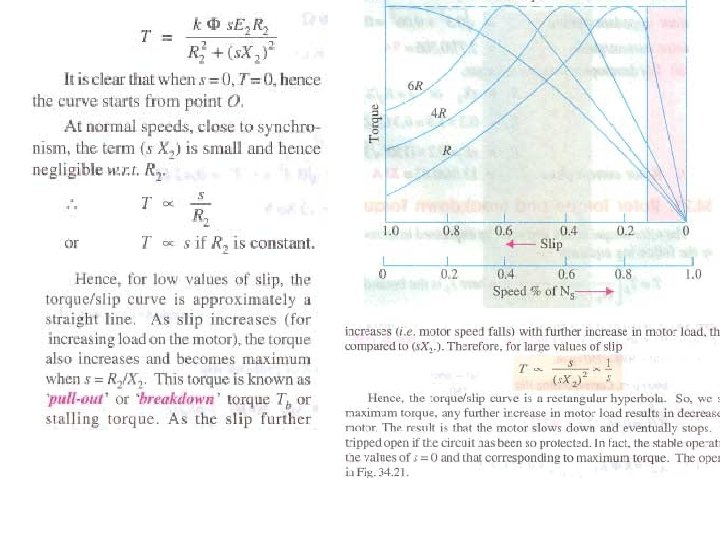
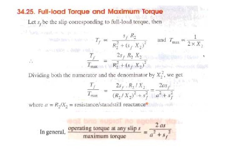
Torque produced by induction motor Firstly the magnitude of rotor current Secondly the flux which interact with the rotor of three phase induction motor and is responsible for producing emf in the rotor part of induction motor lastly the power factor of rotor of the three phase induction motor.
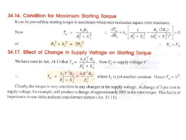
Starting Torque
Starting Torque of Squirrel cage Motor Starting Torque of Wound Rotor Motor