Electrical Energy Storage We can store electric energy

 • When the ends of an electric conductor")

 ◊ the flow of electric charge q that can occur")
 • Why is it necessary to keep pushing the charges")
 is")

 Effect 0. 001")


 The cross-sectional area of a conductor (thickness) is similar to")


 electric circuits • a circuit containing a battery is a DC")


 We have defined potential difference as the")


 stated two simple rules using")


 the total current in the circuit")

- Slides: 46
Electrical Energy Storage + ◊ We can store electric energy in a capacitor : + ++ + ◊ Found in nearly all electronic circuits eg. in photo-flash units. + + + ◊ Simplest is: two close but separated parallel plates. ++ When connected to a battery electrons get transferred from one plate to the other until the potential difference between them = voltage of battery. ◊ How? - -- - Positive battery terminal attracts electrons on LH plate; these are then pumped through battery, through the terminal to the opposite plate. Process continues until no more potential difference btn plate and connected terminal. ◊ Discharging: when conducting path links the two charged plates. ◊ Discharging is what creates the flash in a camera. animation ? ? ♦If very high voltages (eg caps in tv’s), its dangerous if you are this path!
Potential difference or Voltage (symbol V) • When the ends of an electric conductor are at different electric potential, charge flows from one end to the other. Voltage is what causes charge to move in a conductor. Charge moves toward lower potential energy the same way as you would fall from a tree. • Voltage plays a role similar to pressure in a pipe; to get water to flow there must be a pressure difference between the ends, this pressure difference is produced by a pump • A battery is like a pump for charge, it provides the energy for pushing the charges around a circuit
Voltage and current are not the same thing • You can have voltage, but without a path (connection) there is no current. An electrical outlet voltage Current– flow of electric charge If I connect a battery to the ends of the copper bar the electrons in the copper will be pulled toward the positive side of the battery and will flow around. this is called current – flow of charge copper An electric circuit! Duracell +
Electric current (symbol I) ◊ the flow of electric charge q that can occur in solids, liquids and gases. q • DEF: the rate at which charge flows past a given cross-section. • measured in amperes (A) Solids – electrons in metals and graphite, and holes in semiconductors Liquids – positive and negative ions in molten and aqueous electrolytes Gases – electrons and positive ions stripped from gaseous molecules by large potential differences.
Electrical resistance (symbol R) • Why is it necessary to keep pushing the charges to make them move? • The electrons do not move unimpeded through a conductor. As they move they keep bumping into the ions of crystal lattice which either slows them down or bring them to rest. path atoms (actually positive ions) free electron . The resistance (R) is a measure of the degree to which the conductor impedes the flow of current. Resistance is measured in Ohms ( )
OHM’S LAW - Current, Voltage and Resistance • DEF: Current through resistor (conductor) is proportional to potential difference on the resistor if the temperature of a resistor is constant (the resistance of a conductor is constant). ◊ math def: • if resistance R is constant/ temperature is constant • I – current V – potential difference across R
Examples • If a 3 volt flashlight bulb has a resistance of 9 ohms, how much current will it draw? • I = V / R = 3 V / 9 = 1/3 Amps • If a light bulb draws 2 A of current when connected to a 120 volt circuit, what is the resistance of the light bulb? • R = V / I = 120 V / 2 A = 60
Effects of electric current on the BODY- electric shock Current (A) Effect 0. 001 can be felt 0. 005 painful 0. 010 involuntary muscle contractions (spasms) 0. 015 loss of muscle control 0. 070 if through the heart, serious disruption; probably fatal if current lasts for more than 1 second questionable circuits: live (hot) wire ? how to avoid being electrified? 1. keep one hand behind the body (no hand to hand current through the body) 2. touch the wire with the back of the hand. Shock causing muscular contraction will not cause their hands to grip the wire.
human body resistance varies: 100 ohms if soaked with salt water; moist skin - 1000 ohms; normal dry skin – 100 000 ohms, extra dry skin – 500 000 ohms. What would be the current in your body if you touch the terminals of a 12 -V battery with dry hands? I = V/R = 12 V/100 000 = 0. 000 12 A quite harmless But if your hands are moist (fear of AP test? ) and you touch 24 V battery, how much current would you draw? I = V/R = 24 V/1000 = 0. 024 A a dangerous amount of current.
Factors affecting resistance Conductors, semiconductors and insulators differ in their resistance to current flow. DEF: The electrical resistance of a piece of material is defined by the ratio of the potential difference across the material to the current that flows through it. The units of resistance are volts per ampere (VA-1). However, a separate SI unit called the ohm Ω is defined as the resistance through which a current of 1 A flows when a potential difference of 1 V is applied.
Wires, wires As you are going to see, the resistance of a wire can be completely ignored – if it is a thin wire connecting two, three or more resistors, or becoming very important if it is a long, long wire as in the case of iron, washing machine, toaster …. . , where it becomes resistor itself. The resistance of a conducting wire depends on four main factors: • length • cross-sectional area • resistivity • temperature
Cross Sectional Area (A) The cross-sectional area of a conductor (thickness) is similar to the cross section of a hallway. If the hall is very wide, it will allow a high current through it, while a narrow hall would be difficult to get through. Notice that the electrons seem to be moving at the same speed in each one but there are many more electrons in the larger wire. This results in a larger current which leads us to say that the resistance is less in a wire with a larger cross sectional area. Length of the Conductor (L) The length of a conductor is similar to the length of a hallway. A shorter hallway will result in less collisions than a longer one. Temperature To understand the effect of temperature you must picture what happens in a conductor as it is heated. Heat on the atomic or molecular scale is a direct representation of the vibration of the atoms or molecules. Higher temperature means more vibrations. In a cold wire ions in crystal lattice are not vibrating much so the electrons can run between them fairly rapidly. As the conductor heats up, the ions start vibrating. As their motion becomes more erratic they are more likely to get in the way and disrupt the flow of the electrons. As a result, the higher the temperature, the higher the resistance. At extremely low temperatures, some materials, known as superconductors, have no measurable resistance. This is called superconductivity. Gradually, we are creating materials that become superconductors at higher temperatures and the race is on to find or create materials that superconduct at room temperature. We are painfully far away from the finish line.
Resistance also depends on temperature, usually increasing as the temperature increases. At low temperatures some materials, known as superconductors, have no resistance at all. Resistance in wires produces a loss of energy (usually in the form of heat), so materials with no resistance produce no energy loss when currents pass through them. And that means, once set up in motion (current) you don’t need to additional energy in oder to keep them going. The dream: current without cost!!!!! Both in money and damage to environment!!!!
Of course, resistance depends on the material being used. Resistance of a wire when the temperature is kept constant is: The resistivity, ρ (the Greek letter rho), is a value that only depends on the material being used. It is tabulated and you can find it in the books. For example, gold would have a lower value than lead or zinc, because it is a better conductor than they are. The unit is Ω • m. In conclusion, we could say that a short fat cold wire makes the best conductor. If you double the length of a wire, you will double the resistance of the wire. If you double the cross sectional area of a wire you will cut its resistance in half.
Example A copper wire has a length of 160 m and a diameter of 1. 00 mm. If the wire is connected to a 1. 5 -volt battery, how much current flows through the wire? The current can be found from Ohm's Law, V = IR. The V is the battery voltage, so if R can be determined then the current can be calculated. The first step, then, is to find the resistance of the wire: L = 1. 60 m. r = 1. 00 mm r = 1. 72 x 10 -8 m, copper - books The resistance of the wire is then: R = r L/A = (1. 72 x 10 -8 m)(1. 67)/(7. 85 x 10 -7 m 2 ) = 3. 50 The current can now be found from Ohm's Law: I = V / R = 1. 5 / 3. 5 = 0. 428 A
Ohmic and Non-Ohmic conductors How does the current varies with potential difference for some typical devices? current metal at const. temp. filament lamp diode potential difference devices are non-ohmic if resistance changes Devices for which current through them is directly proportional to the potential difference across device are said to be ‘ohmic devices’ or ‘ohmic conductors’ or simply resistors. There are very few devices that are trully ohmic. However, many useful devices obey the law at least over a reasonable range.
Power dissipation in resistors DEF: Electric power is the rate at which energy is supplied to or used by a device. DEF: Power is the rate at which electric energy is converted into another form such as mechanical energy, heat, or light. When a current is flowing through a load such as a resistor, it dissipates energy in it. In collision with lattice ions electrons’ kinetic energy is transferred to the ions, and as a result the amplitude of vibrations of the ions increases and therefore the temperature of the device increases. That thermal energy (internal energy) is then transferred as heat (to the air, food, hair etc. ) by convection, or radiated as light (electric bulb). Where is that energy coming from? This energy is equal to the potential energy lost by the charge as it moves through the potential difference that exists between the terminals of the load.
Power is measured in J s-1 called watts W. If a vacuum cleaner has a power rating of 500 W, it means it is converting electrical energy to mechanical, sound and heat energy at the rate of 500 J s-1. A 60 W light globe converts electrical energy to light and heat energy at the rate of 60 J s -1. Appliance Power rating Blow heater Kettle Toaster Iron Vacuum cleaner Television 2 k. W 1. 5 k. W 1. 2 k. W 850 W 1. 2 k. W 250 W
Deriving expressions for determining power Basic definition of power: Remember: W = q. V → and I = q/t, so P=IV P = IV = V 2/R = I 2 R
In USA you can not get direct information on power of appliance you buy. Look at your hair dryer. If label says “ 10 A”, that means that the power of the hair dryer is 10 x 120=1200 W, or 1. 2 k. W (using a standard US 120 V outlet). Comparison of US and other countries that use voltage of 240 V. As the power of appliances is the roughly the same, the appliances in USA have to draw a greater current, hence have to have less resistance. As the consequence the wires (both used for connecting and in appliances) are thicker in USA. example • How much current is drawn by a 60 Watt light bulb connected to a 120 V power line? P = 60 W = I V = I x 120 so I = 0. 5 A • What is the resistance of the bulb? I = V/R R = V/I = 120 V/0. 5 A R = 240
Paying for electricity • You pay for the total amount of electrical energy (not power) that is used each month • In Irving the cost of electric energy used is 14 ¢ per kilowatt-hour. • How do we get kilowatt-hour and what is that? • Power = energy/time • Energy = power x time, so energy can be expressed in units watts x second what is simply a joule. Physicists measure energy in joules, but utility companies customarily charge energy in units of kilowatt-hours (k. W h), where : Kilowatt-hour (k. Wh) = 103 W x 3600 s 1 k. Wh = 3. 6 x 10⁶ J 1 W x 1 s = 1 J
$$$ example $$$ • At a rate of 14 cents per k. Wh, how much does it cost to keep a 100 W light bulb on for one day? • energy (k. Wh) = power (k. W) x time (h) • energy (k. Wh) = 0. 1 k. W x 24 h = 2. 4 k. Wh cost / day = 2. 4 k. Wh x 14 cents/k. Wh = 33. 6 ¢ for one month that amounts to $ 10. 1.
Direct Current (DC) electric circuits • a circuit containing a battery is a DC circuit • in a DC circuit the current always flows in the same direction. • The direction of the current depends on how you connect the battery Either way the bulb will be on. • a circuit must provide a closed path for the current to circulate around • when the electrons pass through the light bulb they loose some of their energy the conductor (resistor) heats up • the battery is like a pump that re-energizes them each time they pass through it Duracell + The electrons go one way but the current flows the opposite to the direction that the electrons travel. That’s convention. hystoric explanation click me
Drift speed When a battery is connected across the ends of a metal wire, an electric field is produced in the wire. All free electrons in the circuit start moving at the same time. Free electrons are accelerated along their path reaching enormous speeds of about 106 ms-1. They collide with positive ions of crystal lattice generating heat that causes the temperature of the metal to increse. After this event, they are again accelerated because of the electric field, until the next collision occurs. Due to the collisions with positive ions of crystal lattice, hence changing direction, it is estimated that the drift velocity is only a small fraction of a metre each second (about 10 -4 m s-1). example: in an el. circuit of a car, electrons have average drift speed of about 0. 01 cm/s, so it takes ~ 3 hour for an electron to travel through 1 m. it’s not even a snail’s pace!!!!!
• the electricity that you get from the power company is not DC it is AC (alternating) created by an AC electric generator. • In an AC circuit the current reverses direction periodically AC movement of electrons in a wire _ + The current in AC electricity alternates in direction. The back-and-forth motion occurs at freq. of 50 or 60 Hz, depending on the electrical system of the country. !!!!!!! the source of electrons is wire itself – free electrons in it !!!!!! If you are jolted by electric shock, electrons making up the current in your body originate in your body. They do NOT come from the wire through your body into the ground. Alternating electric field causes electrons to vibrate. Small vibrations – tingle; large vibrations can be fatal.
current How does the voltage and current change in time? DC does not change direction over time; DC current time AC time the actual voltage in a 120 -V AC circuit varies between +170 V and -170 V peaks.
AC vs. DC current • for heaters, hair dryers, irons, toasters, waffle makers, the fact that the current reverses makes no difference. They can be used with either AC or DC electricity. • battery chargers (e. g. , for cell phones) convert the AC to DC • Why do we use AC ? ? DC seems simpler? • late 1800’s the war of the currents • Edison (DC) vs Tesla (Westinghouse) (AC) • Edison opened the first commercial power plane for producing DC in NY in 1892 • Tesla who was hired by George Westinghouse believed that AC was superior • Tesla was right, but Edison never gave up!
Why AC is better than DC • DC power is provided at one voltage only • The major advantage: AC voltages can be transformed to higher or lower voltages (can be stepped up or down to provide any voltage required) • This means that the high voltages used to send electricity over great distances from the power station can be reduced to a safer voltage for use in the house. • This is done by the use of a transformer. • DC is very expensive to transmit over large distances compared to AC (more loss to heat), so many plants are required • DC power plants must be close to users • AC plants can be far outside cities • by 1895 DC was out and AC was in
Electromotive force (emf – ε or E) We have defined potential difference as the amount of work that has to be done to move a unit positive charge from one point to the other in an electric field. A battery or an electric generator that transforms one type of energy into electric energy is called source of electromotive force • DEF: emf (ε) of the source is the potential difference between the terminals when NO current flows to an external circuit. (IT IS A VOLTAGE NOT A FORCE). In the true sense, electromotive force (emf) is the work (energy) per unit charge made available by an electrical source.
D. C. circuit analysis Electric Circuits: Any path along which electrons can flow is a circuit. For a continuous flow of electrons, there must be a complete circuit with no gaps. A gap is usually provided by an electric switch that can be opened or closed to either cut off or allow electron flow. An electric circuit has three essential components 1. A source of emf. 2. A conducting pathway obtained by conducting wires or some alternative. 3. A load to consume energy such as a filament globe, other resistors and electronic components. When the switch is closed, a current exists almost immediately in all circuit. The current does not “pile up” anywhere but flows through the whole circuit. Electrons in all circuit begin to move at once. Eventually the electrons move all the way around the circuit. A break anywhere in the path results in an open circuit, and the flow of electrons ceases.
Terminal voltage, emf and internal resistance In the circuit the total energy supplied is determined by the value of the emf. When electrons flow around a circuit, they gain potential energy in the cell and then lose the energy in the resistors. In a closed circuits charge must flow between the electrodes of the battery and there is always some hindrance to completely free flow. So when the current I is drawn from the battery there is some resistance called INTERNAL RESISTANCE (r ) of the battery causing the voltage between terminals to drop below the maximum value specified by the battery’s emf. Thus the TERMINAL VOLTAGE (the actual voltage delivered) is: V = e - Ir
In the mid-nineteenth century, G. R. Kirchoff (1824 -1887) stated two simple rules using the laws of conservation of energy and charge to help in the analysis of direct current circuits. These rules are called Kirchoff’s rules.
1. Junction rule – conservation of charge. ‘The sum of the currents flowing into a point in a circuit equals the sum of the currents flowing out at that point’. I 1 + I 2 = I 3 + I 4 + I 5 2. loop rule – conservation of energy principle: Energy supplied equals the energy released in this closed path ‘In a closed loop, the sum of the emfs equals the sum of the potential drops’. V = V 1 + V 2 + V 3
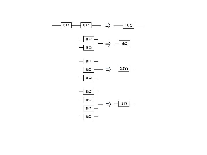
Resistors in Series • connected in such a way that all components have the same current through them. • Burning out of one of the lamp filaments or simply opening the switch could cause such a break. Equivalent or total or effective or resistance is the one that could replace all resistors resulting in the same current. logic: the total or effective resistance would have length L 1+ L 2+ L 3 and resistance is proportional to the length
Resistors in Parallel • Electric devices connected in parallel are connected to the same two points of an electric circuit, so all components have the same potential difference across them. • The current flowing into the point of splitting is equal to the sum of the currents flowing out at that point: I = I 1 + I 2 + I 3. • A break in any one path does not interrupt the flow of charge in the other paths. Each device operates independently of the other devices. The greater resistance, the smaller curent. equivelent resistance is smaller than the smallest resistance.
RESISTORS IN COMPOUND CIRCUITS Now you can calculate current, potential drop and power dissipated through each resistor
example: Find power of the source, current in each resistor, terminal potential, potential drop across each resistor and power dissipated in each resistor. I = ε/Req = 0. 3 A Req = 120 terminal potential: V = ε – Ir = 36 – 0. 3 x 6. 7 = 34 V current through resistors 100Ω and 50Ω : 0. 3 = I 1 + I 2 100 I 1 = 50 I 2 I = I 1 + I 2 → I 1 = 0. 1 A potential drops V = IR power dissipated P = IV 80 Ω 0. 3 x 80 = 24 V 0. 3 x 24 = 7. 2 W 100 Ω 0. 1 x 100 = 10 V 0. 1 x 10 = 1 W 50 Ω 0. 2 x 50 = 10 V 0. 2 x 10 = 2 W 6. 7 Ω 0. 3 x 6. 7 = 2 V 0. 3 x 2 = 0. 6 W I 1 R 1 = I 2 R 2 I 2 = 0. 2 A ε = Σ all potential drops 36 V = 2 V + 24 V + 10 V power dissipated in the circuit = power of the source 0. 6 + 2 + 1 + 7. 2 = 0. 3 x 36
Ammeters and voltmeters In practical use, we need to be able to measure currents through components and voltages across various components in electrical circuits. To do this, we use AMMETERS and VOLTMETERS.
An ammeter – measures current passing through it • is always connected in series with a component we want to measure in order that whatever current passes through the component also passes the ammeter. • has a very low resistance compared with the resistance of the circuit so that it will not alter the current being measured. • would ideally have no resistance with no potential difference across it so no energy would be dissipated in it.
A voltmeter – measures voltage drop between two points • is always connected across a device (in parallel). • has a very high resistance so that it takes very little current from the device whose potential difference is being measured. • an ideal voltmeter would have infinite resistance with no current passing through it and no energy would be dissipated in it.
A potential divider In electronic systems, it is often necessary to obtain smaller voltages from larger voltages for the various electronic circuits. A potential divider is a device that produces the required voltage for a component from a larger voltage. It consists of a series of resistors or a rheostat (variable resistor) connected in series in a circuit. Potential divider equation
example: In the potential divider shown, calculate: (a) the total current in the circuit (b) the potential difference across each resistor (c) the voltmeter reading if it was connected between terminals 2 and 6. (a) The total resistance R = 12 Ω. I = V / R = 12 V / 12 Ω = 1 A (b) 6 x V = 12 V → V = 2 V (12 V is equally shared by each 2 Ω resistor. or V = IR = 1 x 2 = 2 V (c) R = 4 x 2 = 8 Ω (Between terminals 2 and 6 there are 4 resistors) potential difference between the terminals is V = IR = 1 x 8 = 8 V
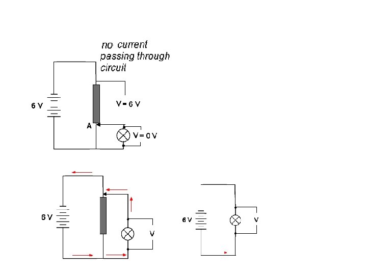
Potentiometer Because resistance is directly proportional to the length of a resistor, a variable resistor also known as a potentiometer or as a “pot” can also be used to control the potential difference across some device. Sliding contact A can connect anywhere from one end to the other of the resistor chain. This way it can control voltage across a device and therefore the current through it, from maximm down to zero. 1. step is to do a circuit without device and then adjust point A in such a way that there is no current passing through potentiometer. Potential difference across potentiometer is 6 V. For some other battery point A would be somewhere else. If you include a lamp into circuit and the pointer is at A, potential difference across the lamp is zero. However, if the pointer is moved up to two-thirds the length of the potentiometer as in the figure, then the output voltage across the filament lamp would be ⅔ × 6 V = 4 V. Pots have a rotating wheel mounted in plastic and they are commonly used as volume and tone controls in sound systems. They can be made from wire, metal oxides or carbon compounds.