
Electrical components and systems Topic Connect a three


- Slides: 38
Electrical components and systems Topic – Connect a three phase energy meter
Connect a three phase energy meter Unit 7. 3
Assumed prior learning Using energy meters Connect a single phase energy meter • Don’t feel confident yet about these topics? Click on each to review the content. • Feeling confident? Click next to proceed with this unit.
Outcomes • Connect a three-phase, three-wire energy meter to a three-phase load. • Connect a three-phase four-wire energy meter to a three-phase load. • Connect a three-phase energy meter with range extension. • Connect an energy meter to a balanced load.
Introduction The connections of a single-phase energy meter and the recording of the readings of the dials were explained in earlier lessons. Make sure you go over those lessons before starting this one. In this lesson we look at the methods to measure the power in a 3 phase system.
Measuring the power in a 3 -phase system The power in a 3 -phase system can either be measured by means of the one-wattmeter or the two-wattmeter method or by using the 3 phase wattmeter.
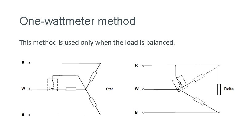
One-wattmeter method This method is used only when the load is balanced.
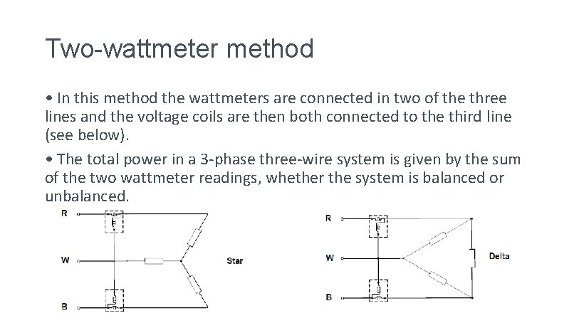
Two-wattmeter method • In this method the wattmeters are connected in two of the three lines and the voltage coils are then both connected to the third line (see below). • The total power in a 3 -phase three-wire system is given by the sum of the two wattmeter readings, whether the system is balanced or unbalanced.
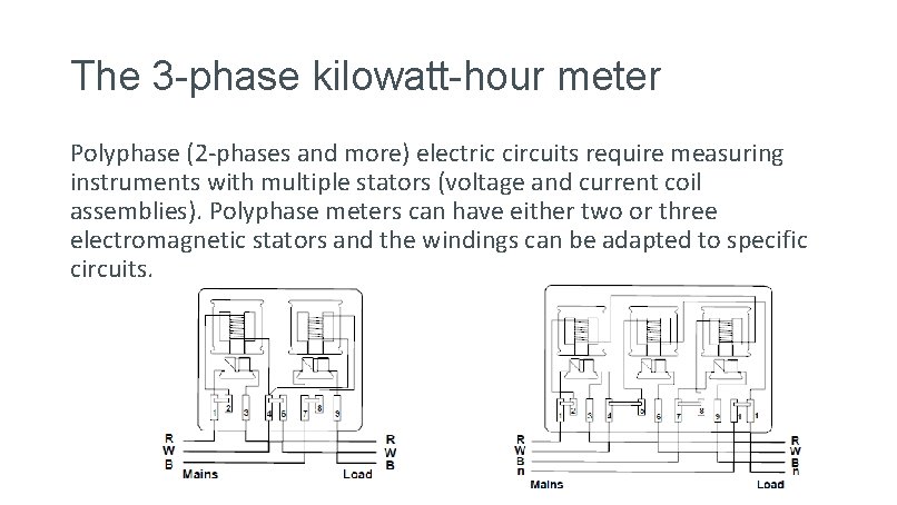
The 3 -phase kilowatt-hour meter Polyphase (2 -phases and more) electric circuits require measuring instruments with multiple stators (voltage and current coil assemblies). Polyphase meters can have either two or three electromagnetic stators and the windings can be adapted to specific circuits.
What is the difference between a balanced load and unbalanced load? Watch the video below for an explanation of the difference between a balanced and unbalanced load in a three phase circuit. Balanced load vs unbalanced load
Blondel’s theorem states: to measure the power in a circuit having N wires, it is necessary to have N minus 1 wattmeters, with the voltage coils connected to a common wire which is usually earthed, and a current coil in each of the phases. • The design of some meters does not completely conform to Blondel's theorem. However, the error involved is insignificant.
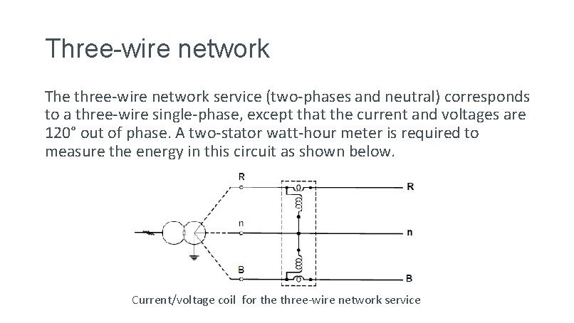
Three-wire network The three-wire network service (two-phases and neutral) corresponds to a three-wire single-phase, except that the current and voltages are 120° out of phase. A two-stator watt-hour meter is required to measure the energy in this circuit as shown below. Current/voltage coil for the three-wire network service
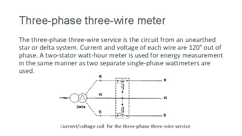
Three-phase three-wire meter The three-phase three-wire service is the circuit from an unearthed star or delta system. Current and voltage of each wire are 120° out of phase. A two-stator watt-hour meter is used for energy measurement in the same manner as two separate single-phase wattmeters are used. Current/voltage coil for the three-phase three-wire service
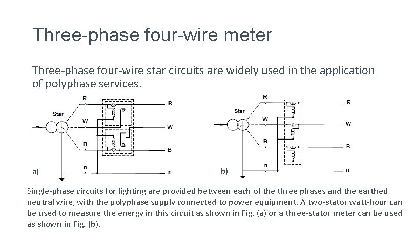
Three-phase four-wire meter Three-phase four-wire star circuits are widely used in the application of polyphase services. a) b) Single-phase circuits for lighting are provided between each of the three phases and the earthed neutral wire, with the polyphase supply connected to power equipment. A two-stator watt-hour can be used to measure the energy in this circuit as shown in Fig. (a) or a three-stator meter can be used as shown in Fig. (b).
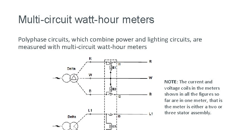
Multi-circuit watt-hour meters Polyphase circuits, which combine power and lighting circuits, are measured with multi-circuit watt-hour meters NOTE: The current and voltage coils in the meters shown in all the figures so far are in one meter, that is the meter is either a two or three stator assembly.
Quiz time Before you wire a kilowatt-hour meter, answer the following questions.
Question 1 In a three phase-machine the most common starting points of the different phase windings are? a) b) c) d) 30 electrical degrees apart 90 electrical degrees apart 120 electrical degrees apart 270 electrical degrees apart
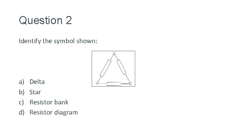
Question 2 Identify the symbol shown: a) b) c) d) Delta Star Resistor bank Resistor diagram
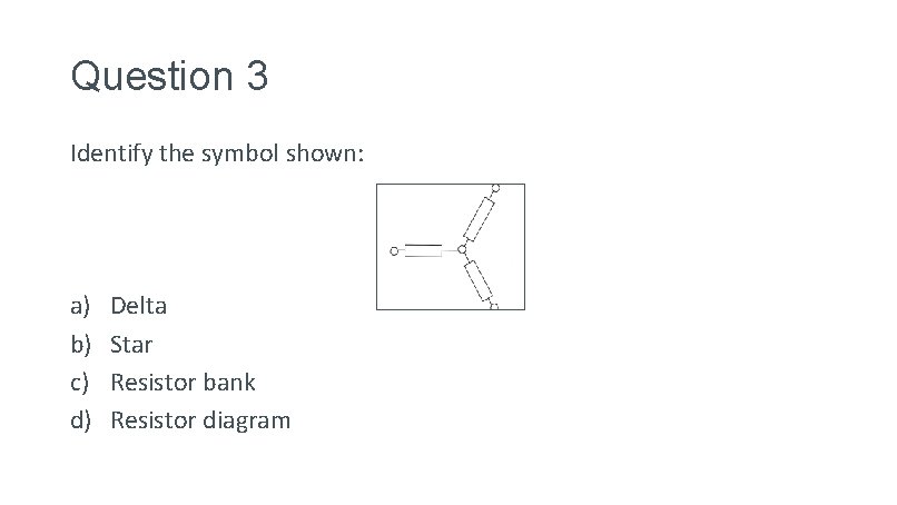
Question 3 Identify the symbol shown: a) b) c) d) Delta Star Resistor bank Resistor diagram
Question 4 What electrical measuring instrument could be used to measure the amount of electricity used per hour? a) b) c) d) Voltmeter Ammeter Kilowatt hour meter Time switch
Question 5 Which of these circuit diagrams show a three-phase four-wire service system being measured by a two-stator watthour meter? A) B) Click on the correct diagram.
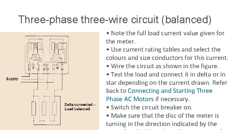
Connecting a three-phase energy meter to a load The load to be used in this lesson is taken as a balanced load. The balancing of three-phase loads is only done in a later lesson. The load must first be connected in delta for the three-phase balanced load, and then in star, with the neutral connected to the star-point, for the three-phase four-wire unbalanced circuit.
Three-phase three-wire circuit (balanced) • Note the full load current value given for the meter. • Use current rating tables and select the colours and size conductors for this current. • Wire the circuit as shown in the figure. • Test the load and connect it in delta or in star depending on the current drawn. Refer back to Connecting and Starting Three Phase AC Motors if necessary. • Switch the circuit breaker on. • Make sure that the disc of the meter is turning in the direction indicated by the
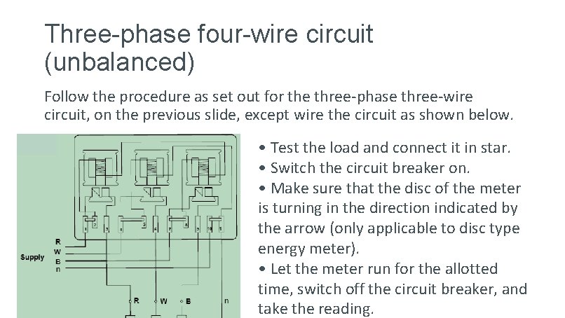
Three-phase four-wire circuit (unbalanced) Follow the procedure as set out for the three-phase three-wire circuit, on the previous slide, except wire the circuit as shown below. • Test the load and connect it in star. • Switch the circuit breaker on. • Make sure that the disc of the meter is turning in the direction indicated by the arrow (only applicable to disc type energy meter). • Let the meter run for the allotted time, switch off the circuit breaker, and take the reading.
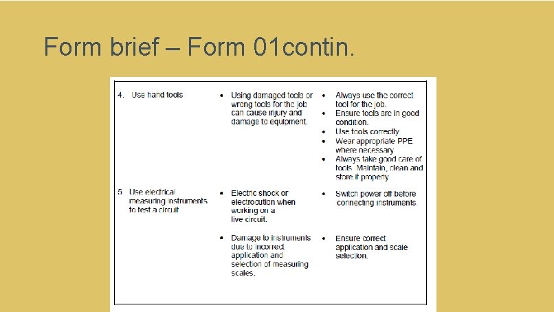
Practise connecting a three-phase 3 -wire and a three-phase 4 -wire energy meter to a load as explained in this lesson. • Vary the size of the load, let the meter run for a specific time period and read the meter. • Measure the load and check the reading by calculation. The conductor sizes must be checked and changed, if necessary, each time that the load is changed. REMEMBER to adhere to the relevant safety procedures when doing the practical work. Refer to the HIAC Form.
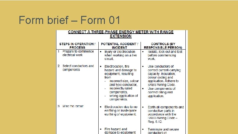
Connect a three-phase energy meter with range extension Next you will learn how to connect a three-phase energy meter to a load through a potential and current transformer, thereby extending the range of the energy meter. HIAC form
Designing the meter • When energy has to be measured in three-phase circuits, which have a voltage higher than 500 volts and a current in excess of 100 amps, it becomes difficult to insulate the coils effectively. • Another problem, which arises, is the size of the instrument. As the voltage and current increase so the insulation and the wires must increase in size. • Thus to effectively prevent the meter from becoming too large and bulky it is necessary to design the meter for a maximum voltage and current. The meter is designed for a maximum operating voltage of 110 volts and a maximum operating current of 5 amps. • The energy meter is equipped with a potential transformer, which steps the voltage down from the line supply voltage to 110 volts, and current transformers, which reduces the load current to a maximum of 5 amps.
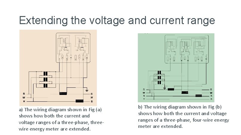
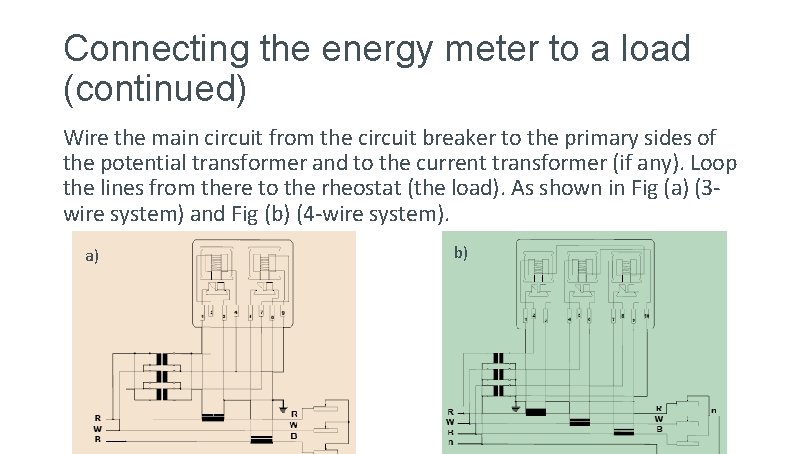
Extending the voltage and current range a) The wiring diagram shown in Fig (a) shows how both the current and voltage ranges of a three-phase, threewire energy meter are extended. b) The wiring diagram shown in Fig (b) shows how both the current and voltage ranges of a three-phase, four-wire energy meter are extended.
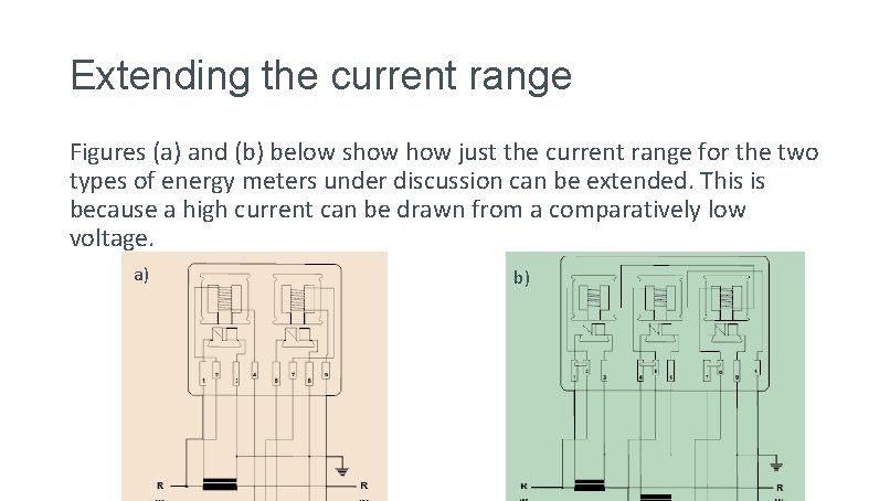
Extending the current range Figures (a) and (b) below show just the current range for the two types of energy meters under discussion can be extended. This is because a high current can be drawn from a comparatively low voltage. a) b)
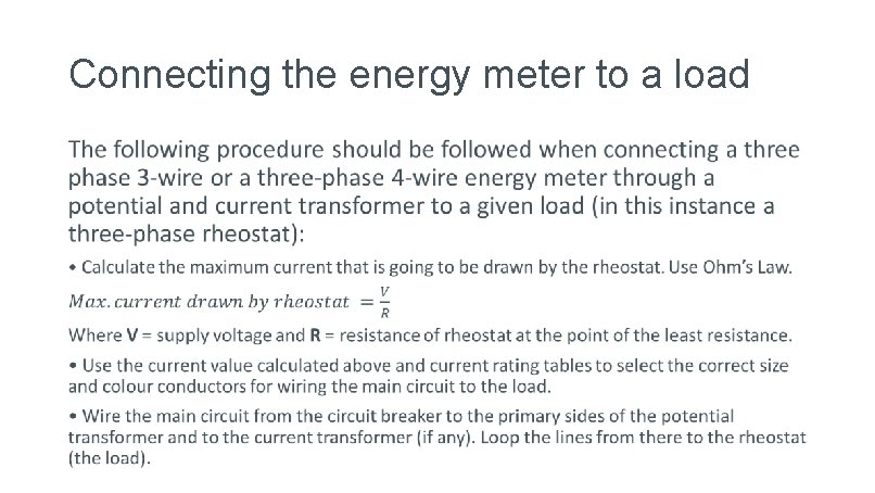
Connecting the energy meter to a load •
Connecting the energy meter to a load (continued) Wire the main circuit from the circuit breaker to the primary sides of the potential transformer and to the current transformer (if any). Loop the lines from there to the rheostat (the load). As shown in Fig (a) (3 wire system) and Fig (b) (4 -wire system). a) b)
Connecting the energy meter to a load (continued) • Wire the secondary circuit from the secondary sides of the potential and the current transformers to the energy meter connections. • Check the connections and the circuit again. • Make sure that the installation is properly earthed. • Test the circuit and correct any faults before switching on the supply. • If you are using the old disc type energy meter, make sure that it turns in the right direction. • Measure the current and voltage in the supply lines and the energy meter circuit. Multiply the ammeter and voltmeter readings on the secondary side by the transformer ratios and see if it is the same as the main supply line readings.
Example to illustrate range extension Ammeter readings (secondary side) Current indicated on the ammeter = 3, 7 amps Current transformer ratio = 1: 10 Thus the current in the circuit = 3, 7 x 10= 37 amps Voltmeter readings (secondary side) Voltage indicates on the voltmeter = 100 volts Potential transformer ratio = 5: 1 Thus the voltage in the circuit = 100 x 5= 500 volts
Practise connecting three-phase, 3 -wire and three-phase, 4 -wire energy meters to a load through current and potential transformers. • Measure the currents and voltages in the circuits and demonstrate, by calculation, the concept of range extension. • REMEMBER to adhere to all the relevant safety procedures when doing the practical work. Refer to the HIAC Form.
Let’s review: In this lesson we have covered: üMeasuring the power in a three phase system. üWattmeters. üExtending the voltage and current range energy meters. üConnecting energy meters to a balanced load. Make sure you have a complete understanding of all the work covered here before you start the next unit.
Video brief - Vid 01 Get link to; 3 phase balanced vs 3 phase unbalanced load https: //www. youtube. com/watch? v=n. Rzs. H 0 pl. XIc
Form brief – Form 01
Form brief – Form 01 contin.