
ELECTRICAL CIRCUITS All you need to be an
ELECTRICAL CIRCUITS All you need to be an inventor is a good imagination and a pile of junk. -Thomas Edison
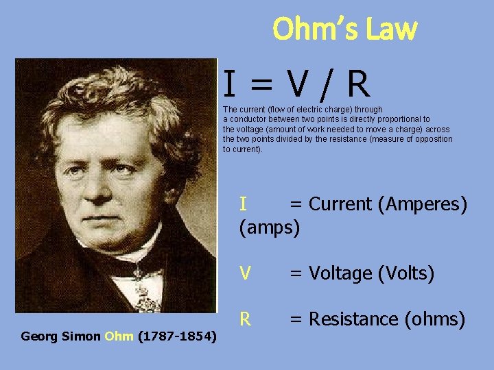
Ohm’s Law I=V/R The current (flow of electric charge) through a conductor between two points is directly proportional to the voltage (amount of work needed to move a charge) across the two points divided by the resistance (measure of opposition to current). I = Current (Amperes) (amps) Georg Simon Ohm (1787 -1854) V = Voltage (Volts) R = Resistance (ohms)
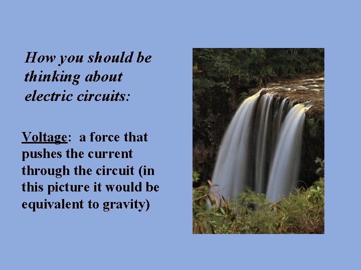
How you should be thinking about electric circuits: Voltage: a force that pushes the current through the circuit (in this picture it would be equivalent to gravity)
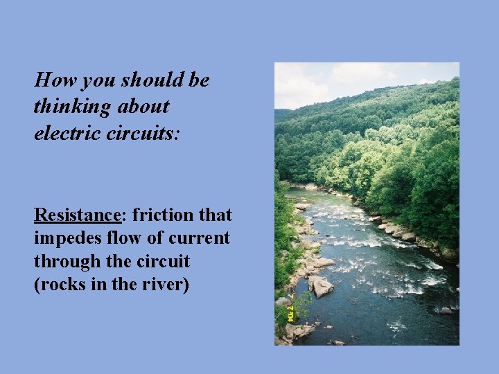
How you should be thinking about electric circuits: Resistance: friction that impedes flow of current through the circuit (rocks in the river)
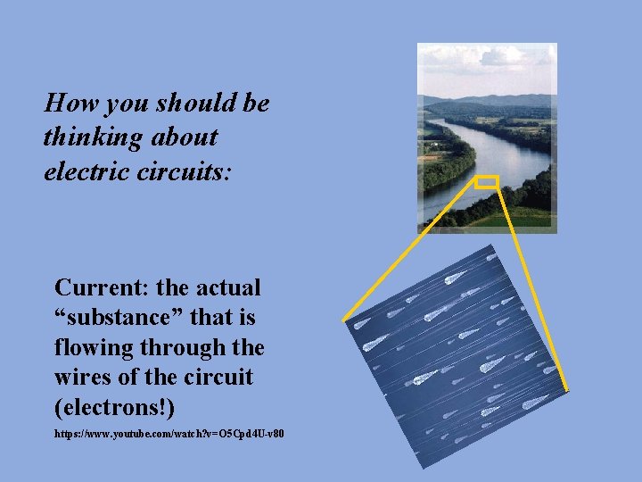
How you should be thinking about electric circuits: Current: the actual “substance” that is flowing through the wires of the circuit (electrons!) https: //www. youtube. com/watch? v=O 5 Cpd 4 U-v 80
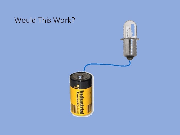
Would This Work?
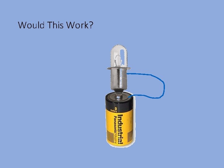
Would This Work?
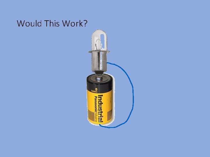
Would This Work?
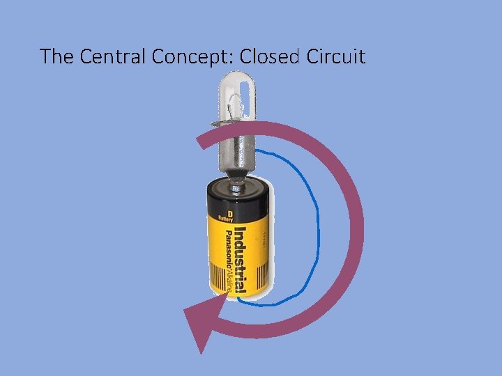
The Central Concept: Closed Circuit
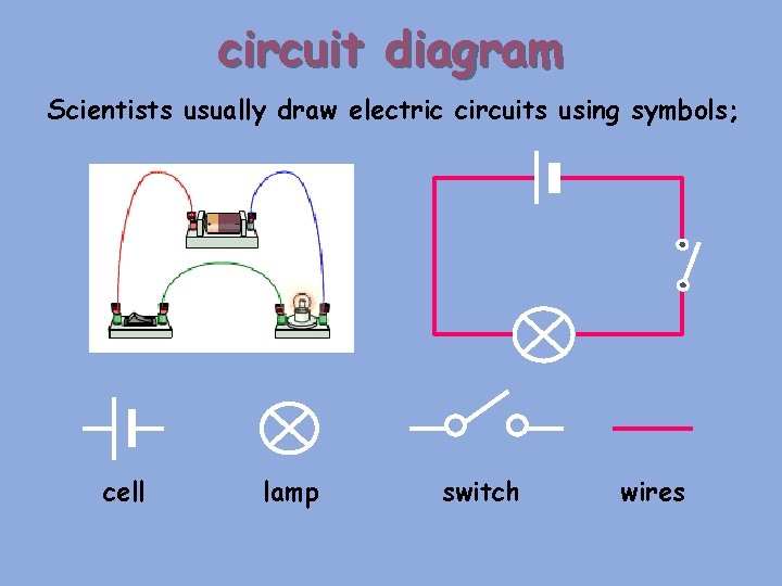
circuit diagram Scientists usually draw electric circuits using symbols; cell lamp switch wires
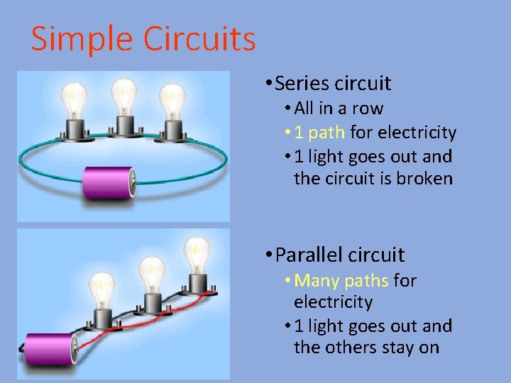
Simple Circuits • Series circuit • All in a row • 1 path for electricity • 1 light goes out and the circuit is broken • Parallel circuit • Many paths for electricity • 1 light goes out and the others stay on
• Series Circuits • only one end of each component is connected • e. g. Christmas tree lights • Parallel Circuits • both ends of a component are connected • e. g. household lighting
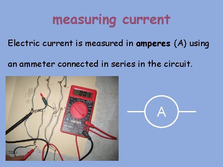
measuring current Electric current is measured in amperes (A) using an ammeter connected in series in the circuit. A
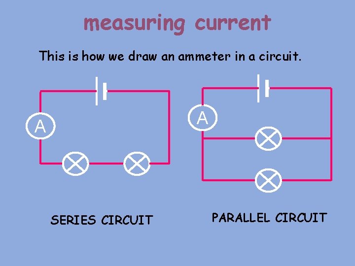
measuring current This is how we draw an ammeter in a circuit. A A SERIES CIRCUIT PARALLEL CIRCUIT
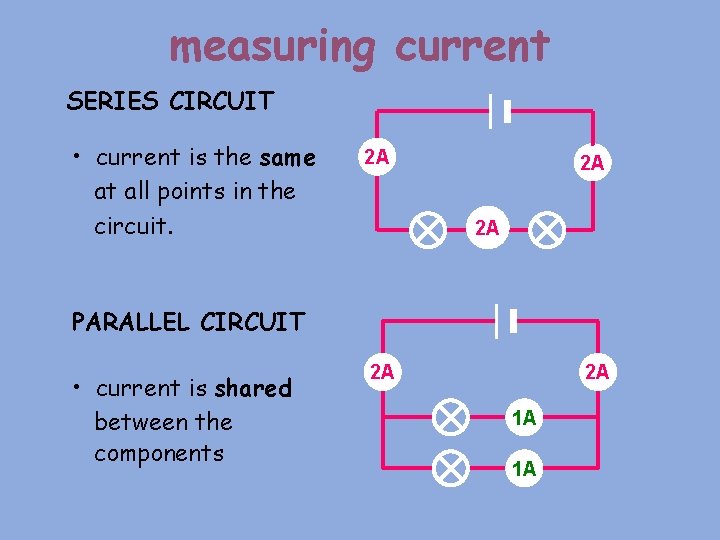
measuring current SERIES CIRCUIT • current is the same at all points in the circuit. 2 A 2 A 2 A PARALLEL CIRCUIT • current is shared between the components 2 A 2 A 1 A 1 A
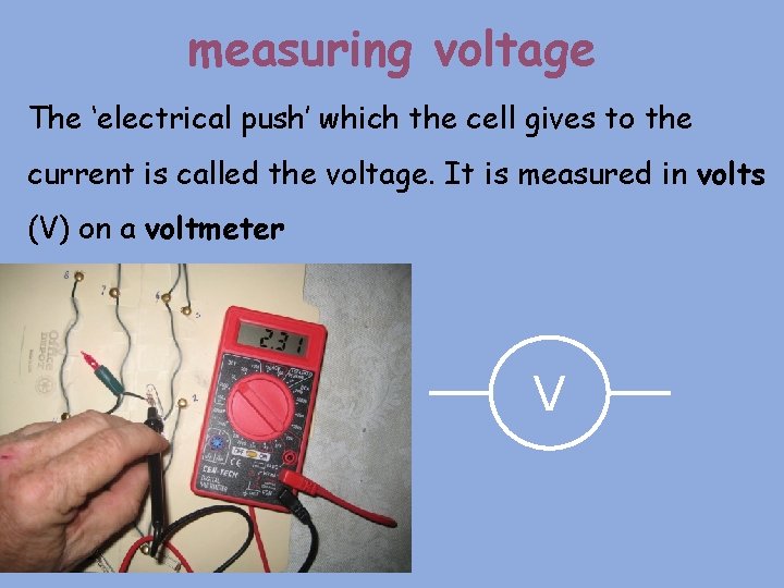
measuring voltage The ‘electrical push’ which the cell gives to the current is called the voltage. It is measured in volts (V) on a voltmeter V
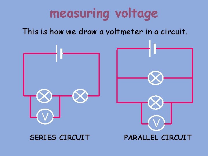
measuring voltage This is how we draw a voltmeter in a circuit. V SERIES CIRCUIT V PARALLEL CIRCUIT
measuring voltage Different cells produce different voltages. The bigger the voltage supplied by the cell, the bigger the current. Unlike an ammeter, a voltmeter is connected across the components Scientist usually use the term Potential Difference (pd) when they talk about voltage.
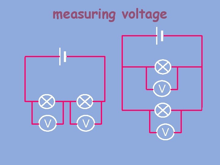
measuring voltage V V
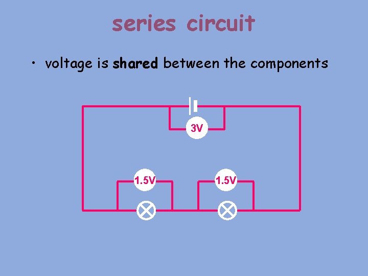
series circuit • voltage is shared between the components 3 V 1. 5 V
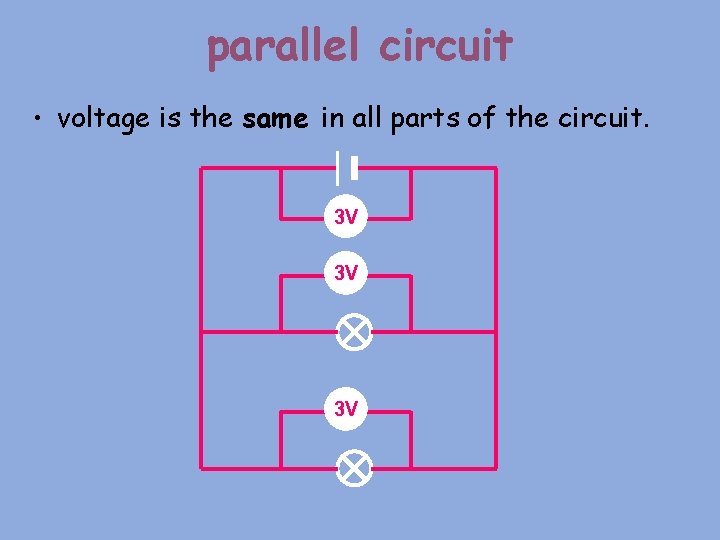
parallel circuit • voltage is the same in all parts of the circuit. 3 V 3 V 3 V
Copy the following charts into your journal and fillin the missing information for both current and voltage.
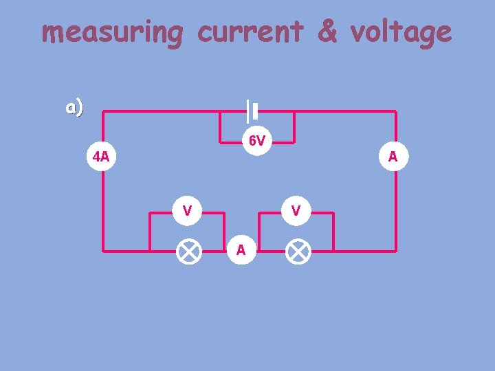
measuring current & voltage a) 6 V 4 A A V V A
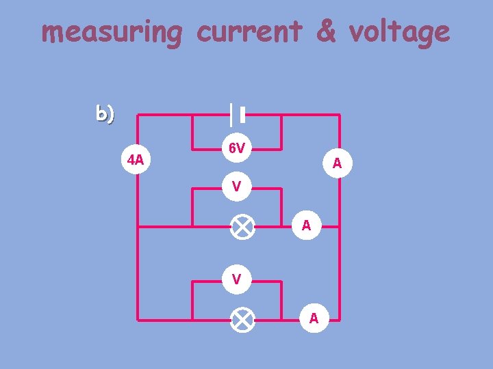
measuring current & voltage b) 4 A 6 V A V A
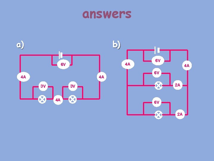
answers a) b) 4 A 6 V 4 A 4 A 3 V 6 V 4 A 6 V 2 A 3 V 4 A 6 V 2 A
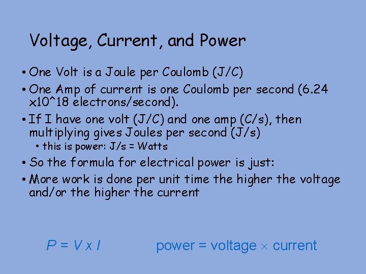
Voltage, Current, and Power • One Volt is a Joule per Coulomb (J/C) • One Amp of current is one Coulomb per second (6. 24 x 10^18 electrons/second). • If I have one volt (J/C) and one amp (C/s), then multiplying gives Joules per second (J/s) • this is power: J/s = Watts • So the formula for electrical power is just: • More work is done per unit time the higher the voltage and/or the higher the current P=Vx. I power = voltage current
- Slides: 27