ELECTRIC SHOCK AND EARTHING Presentation by Kishor Ghimire222
 Ramesh Adhikari(233)")
ELECTRIC SHOCK AND EARTHING Presentation by: Kishor Ghimire(222) Ramesh Adhikari(233)

ELECTRICAL SHOCKS v Electric shock is the physiological reaction or injury occurs when the human body becomes part of the path through which current flows

BASIC CIRCUIT ANALYSIS

FACTOR DETERMINING SHOCK INTENSITY v. The current strength

FACTOR DETERMINING SHOCK INTENSITY CONTD. . v The body resistance v Frequency of current v The path taken by the current v Duration of the contact v Area of contact

IMPLEMENTATION v. Execution by electrocution electric chair, employed as an official method of capital punishment developed throughout the 1880 s v. Researchers found electroconvulsive therapy (ECT) to be more effective than the use of drugs to treat short-term depression

IMPLEMENTATION CONTD. . v. Electric Fencing

SAFETY

FIRST-AID CURE Artificial respiration Mouth to mouth respiration

EARTHING �WHAT IS EARTHING? �Connections of neutral parts of the electrical equipment to the general mass of the earth for immediate discharge of electric energy without danger.

OBJECTIVES The PRIMARY goal is SAFETY. Why ground at all? PERSONNEL SAFETY FIRST EQUIPMENT PROTECTION SECOND

EARTHING SYSTEM EARTHING Deals with the Earthing of current carrying parts of the equipment EQUIPMENT EARTHING Deals with the Earthing of noncurrent carrying parts of the equipment

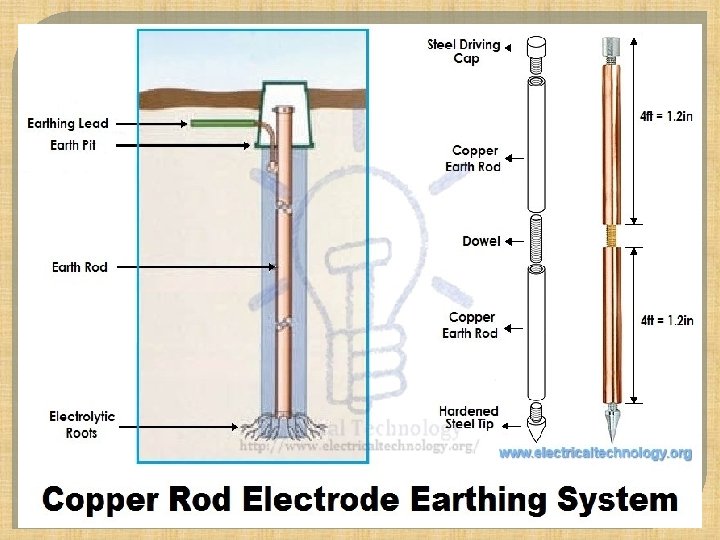
EARTHING SYSTEM Simplest form is a SINGLE STAKE Mostly used for: • Lightning protection • Stand alone structures • Back-up for utility ground Ground rod

GROUND ROD GROUP �typically for lightning protection on larger structures or protection around potential hotspots such as substations Ground rod group
 fairly")
GROUND PLATE �For areas where there is rock (or other poor conducting material) fairly close to the surface Ground plate

GROUND MESH �A ground mesh consists of network of bars connected together, this system is often used at larger sites such as electrical substations. Ground mesh

SOIL CHARACTERISTICS �Soil type. Soil resistivity varies widely depending on soil type, from as low as 1 Ohmmeter for moist loamy top soil to almost 10, 000 Ohm-meters for surface limestone.

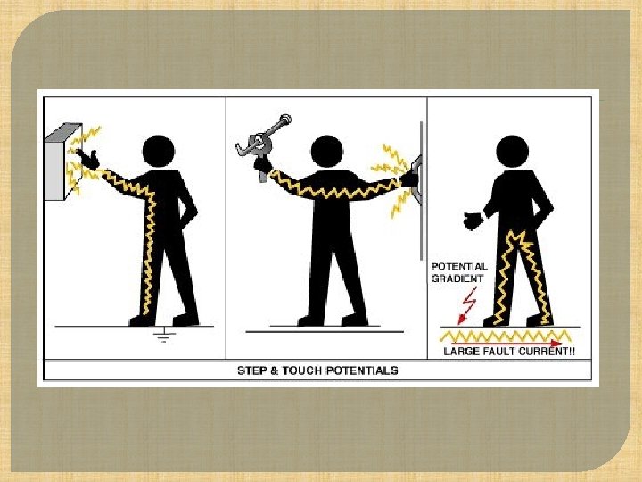
STEP AND TOUCH VOLTAGES
 Resistivity measurements are performed by using")
GROUND TESTING METHODS RESISTIVITY MEASUREMENT ( WENNER METHOD) Resistivity measurements are performed by using a four wire method Used to determine which KIND of earthing should used, BEFORE placing earth stakes.

MEASUREMENT OF RESISTANCE §The distance between the earth ground stacks is at least three times greater than the stake depth. §The soil resistivity measurement are often corrupted by the existence of ground currents and their harmonics. It uses Automatic Frequency Control (AFC) system to prevent from it.

RESISTIVITY MEASUREMENT From the indicated resistance value RE, the soil resistivity is calculated according to the equation : E = 2 . a. R E E RE a . . . mean value of soil resistivity (W. m). . . measured resistance (W). . . probe distance (m)

METHODS OF DECREASING GROUND RESISTANCE �Decreasing the ground resistance of a grounding system in high resistivity soil is often a formidable task. �Recently, some new methods have been proposed to decrease ground resistance.

Ø BY INCREASING DEPTH OF EARTHING ELECTRODE

ØBY INCREASING THE NUMBER OF EARTHING ROD

ØRELATION OF SOIL RESISTIVITY WITH MOISTURE AND TEMPERATURE

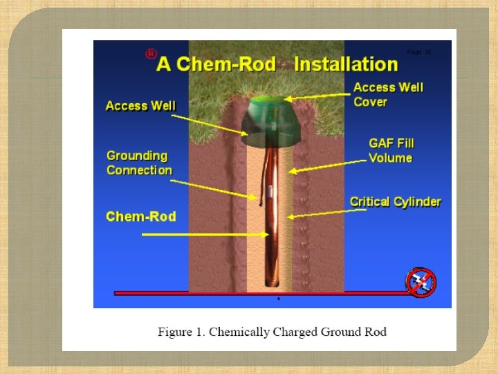
CHEMICAL RODS �Chemical rods are electrodes with holes along their length, filled with mineral salts. �The rod absorbs moisture from both air and soil.

PRICE OF EARTHING WIRE IN NEPAL

THANK YOU
- Slides: 31