Electric Current and Circuits Electric Current Electrons in


 �Q is the charge in coulombs (C)")


 terminal")

 must be wired so that")


- Slides: 33
Electric Current and Circuits
Electric Current �Electrons in a static state have energy, but are far more useful when they are made to transfer their energy. Electric current involves electrons repelling one another and passing through a conductor. �The flow of electric charge is called electric current.
Current �Current is the rate of charge flow and is given the symbol I. Current is the total amount of charge moving past a particular point in a conductor divided by the time taken.
Current �Charge �Time
�I is the current in amperes (A) �Q is the charge in coulombs (C) �t is the time in seconds �One ampere is one coulomb of charge moving past a particular point in a conductor every second. A = C/s
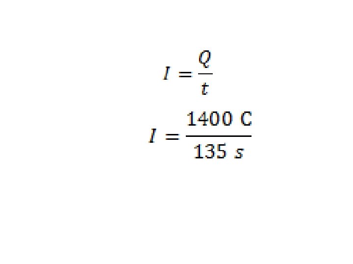
Example 1 �How much current flows through a hair dryer if 1400 C of charge pass though it in 2. 25 min? �Q �I = 1400 C =?
�I = 10. 4 C/s �Therefore, the current through the hair dryer is 10. 4 A.
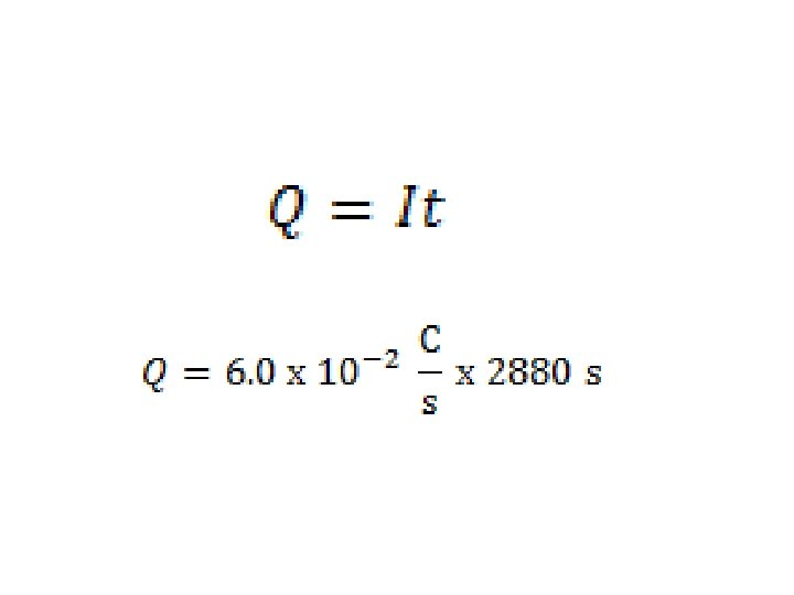
Example 2 �A night light uses a 7 W light that draws about 6. 0 x 10 -2 A of current. How much charges passes through this bulb in 8. 0 hours. �I = 6. 0 x 10 -2 A �Q =?
�Q = 1. 7 x 10² C � �Therefore, the charge through the light bulb is 1. 7 x 10² C
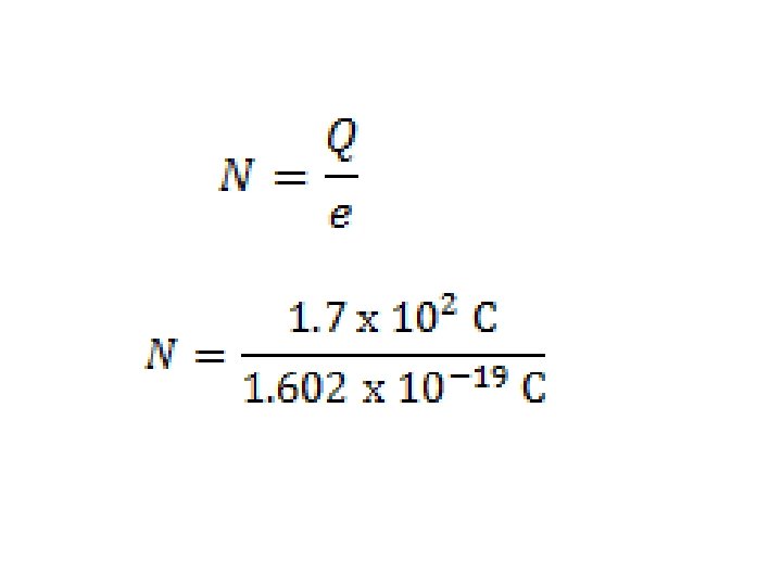
Example 3 �How many electrons have passed through the night light in example 2. The charge on one electron is 1. 602 x 10 -19 C. �Q = 1. 7 x 10² C �e = 1. 602 x 10 -19 C �N = ?
�N = 1. 1 x 10²¹ electrons �Therefore, 1. 1 x 10²² electrons will have passed through the night light in 8 hours.
Direction of Current Flow �Historically, current was thought to flow from positive (+) terminal to the negative (-) terminal of any supply unit. The model of positive charge flow is called conventional current and is still used today.
Direction of Current Flow �For this class we will think of electrons from the black negative (-) terminal to the red positive (+) terminal.
Measurement of current �An Ammeter (a current measuring device) must be wired so that all current flows through it. The ammeter must be an excellent conductor so that no energy is lost due to its addition to the circuit.
�In DC or direct current, the current flows in a single direction from the power supply through the conductor to a load, such as a light bulb, and back to the power supply.
�In AC or alternating current, the electrons periodically reverse the direction of flow.
�In order for electric current to flow, it must have a complete path from the negative side of the power supply to the positive side. The path of electric current is called a circuit.
Drawing circuits Engineers and designers of electrical circuits use special symbols that show the components and connections in a circuit. �A drawing made with these symbols is called a circuit diagram. � Follow these rules when you draw circuit diagrams. 1. Always use a ruler to draw straight lines for the conducting wires. 2. Make right-angle corners so that your finished diagram is a rectangle.
Electric Circuit Diagrams and Symbols �Conductor or wire ◦ To pass current very easily from one part of a circuit to another.
Electric Circuit Diagrams and Symbols �Cell-Supplies electrical energy ◦ The positive end is bigger than the negative end.
Electric Circuit Diagrams and Symbols � 2 Cells �Note: every time a cell is added you need to draw another cell.
Electric Circuit Diagrams and Symbols �DC Source- Electrical energy source ◦ DC = Direct current, always flows one way
Electric Circuit Diagrams and Symbols �AC Source - Electrical energy source �AC = Alternating current, continually changing direction
Electric Circuit Diagrams and Symbols �Ground – ◦ A connection to earth
Electric Circuit Diagrams and Symbols �Switch - An on-off switch allows current to flow only when it is in the closed (on) position
Electric Circuit Diagrams and Symbols �Lamp ◦ A transducer which converts electrical energy to light
Electric Circuit Diagrams and Symbols �Resistor ◦ A resistor restricts the flow of current,
Electric Circuit Diagrams and Symbols �Ammeter ◦ -Device that measures current A
Electric Circuit Diagrams and Symbols �Voltmeter �-Device that measures voltage V
Electric Circuit Diagrams and Symbols Motor -electrical load that converts electrical energy into movement M