Effective bandwidth with link pipelining Pipeline the flight

Effective bandwidth with link pipelining • Pipeline the flight and transmission of packets over the links • Overlap the sending overhead with the transport latency and receiving overhead of prior packets Transport latency Receiving overhead overlap Sending overhead time

Characterizing Performance : Effective Bandwidth Injection bandwidth Network injection Reception bandwidth Aggregate bandwidth Eff. bandwidth = min (BW Network. Injection , BWNetwork. Reception) = min (Nx. BW Link. Injection , Nx. BWLink. Reception) = min (2 x. BW Link. Injection , 2 x. BWLink. Reception) Network reception
 Packet size BWLink. Reception")
Packet size BWLink. Injection = max (sending overhead, transmission time) Packet size BWLink. Reception = max (receiving overhead, transmission time) N x Packet size Eff. bandwidth = min (Nx. BWLink. Injection , Nx. BWLink. Reception) = max (overhead, transmission time) overhead = max (sending overhead, receiving overhead)
 Throughput Performance Model: • The network can")
Characterizing Performance: Effective Bandwidth A Simple (General) Throughput Performance Model: • The network can be considered as a “pipe” of variable width Injection bandwidth Bisection bandwidth Reception bandwidth • There are three points of interest end-to-end: – Injection into the pipe – Narrowest section within pipe (i. e. , minimum network bisection that has traffic crossing it) – Reception from the pipe
 = min(N")
Effective bandwidth = min(BWNetwork. Injection , BWNetwork , σ × BWNetwork. Reception) = min(N × BWLink. Injection , BWNetwork , σ × N × BWLink. Reception) BWNetwork = ρ × BWBisection g

Characterizing Performance: Effective Bandwidth BWNetwork = ρ × BWBisection × 8/3 Injection bandwidth Network injection g Bisection Bandwidth Aggregate bandwidth Reception bandwidth Network reception g = 3/8 unidirectional ring greedy traffic: node i sends to node i + 3 mod N
 Model Applied to Interconnecting Two Devices: Effective bandwidth = min(2 × BWLink.")
Simple (General) Model Applied to Interconnecting Two Devices: Effective bandwidth = min(2 × BWLink. Injection , BWNetwork , 1 × (2 × BWLink. Reception)) BWNetwork = r. L × 2 × BWLink 1 r. L= link efficiency resulting from flow control, encoding, packet header and trailer overheads Dedicated-link network BWLink int. network Device A Device B
 hypercube of 16 nodes Network Bisection 2")
(16 = 24, so n = 4) hypercube of 16 nodes Network Bisection 2 D torus of 16 nodes 2 D mesh or grid of 16 nodes
,")
Network-on-Chip An No. C architecture can be uniquely described by the triple Arch(T(R, Ch), PR, Ω(C)), where, 1. The labeled graph T(R, Ch) represents the network topology. The routers and channels in the network are given by the sets R and Ch, respectively 2. {PR (r, i, j)|i, j, r ∈ R} defines the routing policy PR at router r, for any source router i and destination router j, while considering a particular switching technique. 3. Ω : C → R is a function that maps each vertex ci ∈ C in the APCG to a router in R.

On-chip-network building block Topology v The on-chip-network topology determines the physical layout and connection between nodes and channel in the network. v Metrics for comparing topology § Degree § Hop Count § Maximum channel node § Path Diversity

Example:

Routing v The routing algorithm is used to decide what path a message will take through the network to reach its destination. v Types of routing algorithm § Deterministic routing algorithm § Oblivious routing algorithm § Adaptive routing algorithm

Deterministic routing algorithm send every packet from source x to destination y over exactly the same route. mi = di − si mod k Δi = mi – 0 if mi ≤ k/2 otherwise mi - k This can then be used to compute our preferred directions: DT, i = 0 if |Δi| = k/2 otherwise sign(Δi )
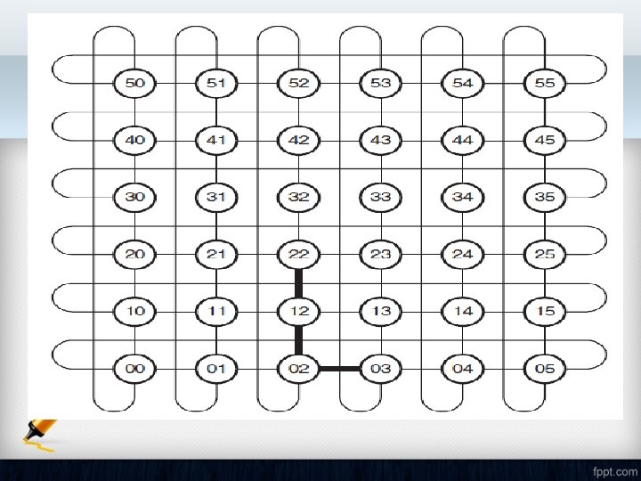

Oblivious routing algorithm Oblivious routing, in which we route packets without regard for the state of the network, is simple to implement and simple to analyze. Intermediate node

Minimal Quadrant Possible routes

Adaptive routing algorithm An adaptive routing algorithm uses information about the network state, typically queue occupancies, to select among alternative paths to deliver a packet. Partial Adaptive routing algorithm

a. Fully Adaptive routing algorithm b. Deadlock condition
- Slides: 18