EET 4163 Electrical Drives Chapter 2 DC Motors

 l =")
 eind is the induced voltage and is equal to the product")
 Commutator + Brushes AC DC (generator)")
 (for motors) Fleming’s Right Hand")
")
")
 Commutator + Brushes DC AC (motor)")
")
 • Basic elements: field circuit, armature circuit, commutator and brushes. •")


 , speed–current equation is obtained:")


 are: • • • 39 For")

 The load could be lost")
 A centrifugal switch can be connected to the motor to de-energize the motor")
")

 shows")


 to include the newly added resistance: • Substituting")


")
- Slides: 62
EET 416/3 Electrical Drives Chapter 2 DC Motors
Induced voltage for one conductor where B = magnetic flux density (T) l = length of conductor (m) v = velocity of the conductor (ms-1) The induced voltage depends on three factor: 1. The flux, Ф in the machine 2. The speed ωm of the machine’s rotor 3. A constant depending on the construction of the machine Induced voltage 1 2
Basic Theory (Generation) eind is the induced voltage and is equal to the product of the flux inside the machine and the speed, v of rotation of the machine, multiplied by a constant representing the mechanical construction of the machine. The total induced voltage on the loop eind is given by; eind = eba + ecb + edc + ead eind = v. Bl + 0 + v. Bl + 0 eind = 2 v. Bl eind = 2 B l v
Basic Theory (Generation) Commutator + Brushes AC DC (generator)
Fleming: LEFT vs RIGHT Fleming’s Left Hand Rule (LHR) (for motors) Fleming’s Right Hand Rule (RHR) (for generators)
Left Hand Rule Fleming’s Left Hand Rule (for motors)
Right-Hand Grip Rule The Right-Hand Grip rule showing the direction of current flow (I) and the magnetic field around a conductor.
Basic Theory (Motoring) Commutator + Brushes DC AC (motor)
Basic Theory (Motoring)
Basic Theory (Motoring) • Basic elements: field circuit, armature circuit, commutator and brushes. • The field can be produced by an electromagnet (fed by a DC power source) or a permanent magnet (e. g. ferrite magnet). • The presence of the stator flux and rotor current produces a force F (known as Lorentz force) on the coil. • This force (as shown in the figure) produces torque that rotates the armature counterclockwise.
Classification of DC Motors Separately Excited DC Motors Shunt DC Motors Series DC Motors Compound DC Motors Permanent Magnet DC Motors • DC motors are grouped according to how the excitation field is produced or how the field circuit is arranged. • Each group exhibits distinct speed-torque characteristics. • Each group is controlled by different means.
DC Motor based on field windings arrangement
SEPARATELY EXCITED DC MOTOR
• Two voltage sources are required. • Field circuit is a permanent magnet for small motor(< few 100 W). Field is constant and cannot be adjusted. • Field current is smaller, therefore the wire cross section of field winding is smaller. • Field current is given as : Ia If • Field resistance > armature resistance.
Ia If • Armature current is much higher • Armature current is given as : • The developed power, Pd is represents by the multiplication of Ia by Ea: • Back electromagnetic force, Ea is equal to the voltage source, Vt minus the voltage drop at armature resistance • Mechanically, it is also equal to the developed torque multiply the angular speed.
• The developed power Pd is equal to the output power consumed by the mechanical load plus rotational losses (frictional and windage). • Similarly, the developed torque Td is equal to the load torque plus the rotational torque. • Back EMF : • Substitute Ea into Pd gives the developed torque: • Substitute Ia into Td gives the developed torque: ω Speed-torque equation Speed-current equation
• Speed–torque equation: • Replace Ia= Td/(Kø) , speed–current equation is obtained:
• If the rotational losses are ignored, the developed torque Td is equal to the load torque (shaft torque), and the no-load armature current can be assumed to be zero. • Hence, the no-load speed can be obtained by setting the load torque or armature current equal to zero. • In reality, the mass of the drive system and the rotational losses are the base load of the motor. The no-load speed is therefore slightly smaller than Vt/(Kø).
• In the steady state, the developed torque Td is equal to the load torque Tm. At a given value of load torque, the speed of the motor drops by an amount of Δw that is equal to the 2 nd term on the right side of speed-torque equation: • The speed of the motor can then be expressed by using the no-load speed and speed drop: Δω
• By setting the motor speed to zero, the equations for the starting current and torque are: • These equations provide information on the starting behavior of this motor. • Since Ra is small, starting torque is large when source voltage is equal the rated value. • It is advantageous when the motor has to start under heavy loading conditions. However, the high currents can cause damage to the motor windings. Excessive current Winding Short circuit 20 Large losses Excessive heat Melt winding insulation Over time
The control of Separately Excited DC motor
How to reduce the starting current? Method 1 • An adjustable voltage source is employed. • This is a common method - highly efficient, stable and simple to implement. • When the armature voltage is reduced, the no-load speed w 0 is also reduced.
• For the same value of load torque and field flux, the armature voltage does not affect the speed drop Δw. • The slope of the speed-torque characteristic is Ra/(Kf)2, which is independent of the armature voltage. Note that we are assuming the field voltage is unchanged when the armature voltage varies. • Hence, the characteristics are parallel lines. • If the voltage keeps decreasing, it will come to the “holding’’ state where the motor speed is zero at point 4.
How to reduce the starting current? Method 2 • If a resistance Radd 1 is added to the armature circuit, the motor operates at point 2, where the motor speed w 2 is • Note that the no-load speed w 0 is unchanged regardless of the value of resistance in the armature circuit. • The 2 nd term of the speed equation is the speed drop Δw 2, which increases in magnitude when Radd increases. Consequently, the motor speed is reduced.
• If the added resistance keeps increasing, the motor speed decreases until the system operates at point 4, where the speed of the motor is zero. • The operation of the drive system at point 4 is known as "holding". • In this case, Radd 3 is given as Keep in mind that operating a dc motor for a period of time with a resistance inserted in the armature circuit is a very inefficient method. The use of resistance is acceptable only when the heat produced by the resistance is utilized as a byproduct or when the resistance is used for a very short period of time.
How to reduce speed? • The same method to reduce the starting current. • Hence, the speed of a separately excited DC motor can be controlled by: Adding an armature resistance Varying the terminal voltage Adjusting the field flux *for small motors (up to few hundreds watts), the field circuit is a permanent magnet. In such case, the flux of the field is constant and cannot be adjusted.
Method 3 for speed control • An adjustable voltage source is connected to the field winding. • If field voltage is reduced, the field current and consequently the field flux are reduced. • When the field flux is reduced, the noload speed w 0 is increased in inverse proportion to the flux, and the speed drop Δw is also increased. The characteristics show that because of Δω the change in speed drops, the lines are not parallel. As Vf reduced Δω
1 a A separately excited DC motor has the E L following data: P M A X E So n o ti u l Kø = 3. 0 Vs Vt = 600. 0 V Ra = 2. 0 Ω Ia (rated) = 5. 0 A Calculate the rated torque, starting torque and starting current at full voltage.
A X E E L P M b the speed-current characteristics of the DC motor. Analyze 1 Sketch the result and discuss. n o ti u l So The starting torque is 60 times the rated torque and the starting current is also 60 times the rated current. Such a high current over a period of time is damaging to the motor winding. While the inductance of the winding may reduce the value of the current during starting (a transient event), the starting current under full voltage conditions is excessively large and appropriate methods must be implemented to bring this current to a lower and safer value.
P M E L A X E n o ti u l c on method to reduce the starting current. Give the calculation 1 Discuss by assuming that the starting current must be limited to six times the rated value. Demonstrate the effect of using the methods to the speedcurrents characteristics of the Dc motor. Method 1 Reduce the terminal voltage, Vt. So When a lower voltage source is used (i. e. 60 V), the slope of the speed-current characteristic remains unchanged, whereas the noload speed is reduced. .
n it o lu Method 2 Add resistance to the armature circuit, Radd So By adding a resistance of 18Ω, the slope of the speed-current characteristics increases, but the no-load speed remain unchanged.
SHUNT MOTORS
• A shunt motor has its field winding connected across the same voltage source used for the armature circuit. • The current of the source I is equal to the sum of the armature current Ia and the field current If. • The shunt motor exhibits characteristics identical to those of the separately excited motor.
E PL M A EX So n o ti u l 2 A 600 V, dc shunt motor has armature and field resistance of 1. 5 Ω and 600Ω respectively. When the motor runs unloaded, the line current is 3 A, and the speed is 1000 rpm. Calculate the developed torque at a full load armature current of 50 A.
E PL M A EX So n o ti u l 3
E PL 3 Efficiency w/o Radd= M A EX So n o ti u l Efficiency w Radd=
SERIES MOTORS
The armature current and developed torque are: Some of the differences between the field windings of shunt and series motors are: • Series field winding has small number of turns compared to shunt. • Series field winding carries a much larger current than the shunt field • winding. Field current of the shunt machine is constant. Field current of the series motor varies with the loading of the motor. It is important to consider the effect of flux saturation due to high field currents when analyzing series machines. 38
The starting current and torque (at low saturation) are: • • • 39 For the same terminal voltage, the starting current of a series motor is lower than that of a shunt motor. Another great feature of series motors is their ability to be driven directly by ac supplies. Due to these features, the series motor is popular in applications such as traction & transportation (e. g. , trolley bus), and also household appliances such as washing machines, drills, blenders, etc.
• At no load or light load speed will be excessively high • Therefore, series motor must always be connected to a mechanical load. 40
if the series motor ever loses its load…… 1) The load could be lost when a shaft breaks or if a drive pin is sheared. 2) When this occurs, the load current is allowed to fall to a minimum, which reduces the amount of back EMF that the armature is producing. 3) Since the armature is not producing a sufficient amount of back EMF and the load is no longer causing a drag on the shaft, the armature will begin to rotate faster and faster. 4) It will continue to increase rotational speed until it is operating at a very high speed. When the armature is operating at high speed, the heavy armature windings will be pulled out of their slots by centrifugal force. 5) When the windings are pulled loose, they will catch on a field winding pole piece and the motor will be severely damaged. 6) This condition is called runaway and you can see why a DC series motor must have some type of runaway protection.
7) A centrifugal switch can be connected to the motor to de-energize the motor starter coil if the rpm exceeds the set amount. 8) Other sensors can be used to de-energize the circuit if the motor's current drops while full voltage is applied to the motor. 9) You can also see from this curve that a DC motor will run away if the load current is reduced to zero. (It should be noted that in larger series machines used in industry, the amount of friction losses will limit the highest speed somewhat. )
The control of Series DC motor (pg 183 -189)
3 methods to control the speed of series DC motor: Adding a resistance in the armature circuit Adjusting the armature voltage Adjusting the field current
Controlling Speed By Adding Resistance To The Armature Circuit • Equation (6. 28) shows that, for a given load torque, the armature current of the motor is constant. The change in armature current is only proportional to the change in the load torque.
• If a resistance Radd is inserted in series with the armature circuit, Equation (6. 29) can then be modified to • If we assume that the load torque is unchanged, then the armature current is constant. In addition, if the supply voltage is unchanged, then the motor speed is reduced when a resistance is added to the armature circuit. This is due to the increase in the speed drop Δw.
Controlling Speed By Adjusting Armature Voltage • The change in armature voltage has a similar effect on the series motor as the insertion of an armature resistance. • For a constant torque, the motor current is constant, and the first term w 0 in Equation (6. 29) decreases with the decrease of voltage. The second term Δw remains unchanged. This results in a decrease in motor speed. • Since the voltage must be kept at or below the rated value, this type of control is suitable for speed reduction below rated speed.
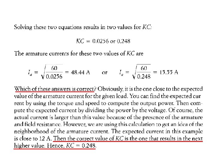
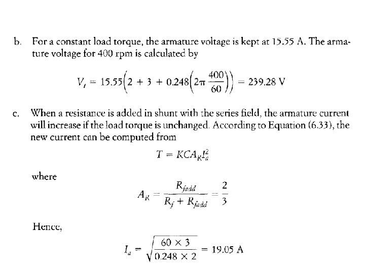
Controlling Speed By Adjusting Field Current • Have 2 methods: 1. Add a shunt resistance to series field circuit 2. Use of a solid-state switching device across the field windings • If a resistance Rfadd is inserted in shunt with the series field winding, the field current is reduced by the following ratio: • If the field flux is assumed to be proportional to the field current, i. e. f = CIf, then • Also, the load torque equation becomes
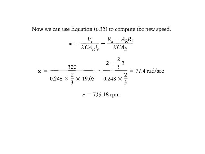
• Modify Equation (6. 27) to include the newly added resistance: • Substituting Equation (6. 32) into (6. 34) yields
• A reduction of Rfadd results in current reduction of the field windings, which leads to an increase in motor speed. • Note that since the technique results in a field reduction, it is suitable for speed increase. • This type of speed control must be performed with care so the current of the motor is not excessive. This can be seen by examining Equation (6. 33); if the torque is assumed constant, the armature current will increase if Rfadd is reduced.
COMPOUND MOTORS
• A compound motor is composed of shunt and series windings. • 2 types of configurations can be used: • Cumulative compound (shown below) – airgap flux is sum of flux of both field windings. • Subtractive compound (unstable) – airgap flux is difference of flux of the two field windings. 52
• The speed-current and torque equations for cumulative compound motors are: • The starting current and torque equations are: 53
54
EX A M P E L 4
So n it o lu
Take home exercises: 1. A l 000 -V, 50 hp dc series motor is used as a hoist. The motor runs at a speed of 750 rev/min at full load. The armature and field resistances are 0. 5 Ω and 2. 0 Ω, respectively. a. If the load torque is reduced by 50%, calculate the motor speed and line current. b. For the load condition in part (a), assume a resistance of 5 Ω is added in series with the field windings. Calculate the motor speed and line current.
Take home exercises: 2. A dc series motor runs a constant-torque load. The terminal voltage of the motor is 200 V, the speed is 500 rev/min, the armature current is 25 A, the armature resistance is 0. 2 Ω, and the field resistance is 0. 6 Ω. If the armature is shunted by a l 0 Ω resistance, calculate the speed of the motor.
ขอบคณ Korb Kun Krup (Thank You)