EET 204 Instrumentation and Measurement Concept and Principles


")


 the materials used for the")


 made by sintering mixtures")
")


 The change in length ΔL ii) The change")


. RTD's are precision temperature sensors made from high-purity conducting metals")


- Slides: 73
EET 204– Instrumentation and Measurement Concept and Principles of Transducers and Sensors Content: 1. Introduction 2. Temperature Sensor 3. Optical Sensor 4. Other Sensor
Lesson Outcomes At the end of the lesson, students should be able to: define basic concept of transducers and sensors apply in-depth knowledge in transducer's and sensor’s application
Objectives: 1. To get familiarize with several types of transducers and selection criteria. 2. Able to apply basic principles of operation and application of common transducer.
Introduction Content: 1. Definition of Transducer 2. Types of Transducers 3. Application of Transducers 4. Advantage of Electrical 5. Transducers 6. Classification Of Transducers 7. Selecting A Transducers 8. Parameter
Introduction DEFINITION OF TRANSDUCER & SENSORS Transducer - device that converts one form of energy into another form of energy sensor - device that measures a physical quantity and converts it into a signal which can be read by an observer or by an instrument. Microphone Speaker Sound > Electrical > Sound Generator Mechanical motion > Electrical Signal
- Introduction TYPES OF TRANSDUCERS Electrical Transducers Converts the input measurand into an electrical voltage/current Mechanical Transducers Converts the input measurand into a mechanical energy
- Introduction APPLICATION OF TRANSDUCERS Electrical Sensor Device that capable to detect electrical signal and sent it to another measurand TRANSDUCER excitation electrical output
- Introduction ADVANTAGES OF ELECTRICAL TRANSDUCERS Electrical amplification and attenuation can be easily done Mass-inertia effects are minimized Effect of friction are minimized
- Introduction ADVANTAGES OF ELECTRICAL TRANSDUCERS The output can be indicated and recorded remotely at a distance from the sensing medium The output can be modified to meet the requirements of indicating or controlling units
- Introduction ADVANTAGES OF ELECTRICAL TRANSDUCERS The signal can be conditioned or mixed to obtain any combination with outputs of similar transducers or control signal "Strive always to excel in virtue and truth. " (Bukhari)
- Introduction CLASSIFICATION OF TRANSDUCERS Active Transducer Do not requires external power produce an analog voltage measurand Active Transducer electrical output
- Introduction CLASSIFICATION OF TRANSDUCERS Passive Transducer Require external power source to operate measurand Passive Transducer external power electrical output
- Introduction SELECTING A TRANDUCER Operating Range Maintain range requirements and good resolution Sensitivity enough to allow sufficient output Environment Compatibility Ability to make it applicable and interactions Accuracy Subject to repeatability and calibration error Physical Condition Depend on its usage Electrical Length and type of cable is required
- Introduction PARAMETER Linearity Relationship between physical parameter and resulting electrical signal must be linear Sensitivity Defined as the electrical output per unit change in physical parameter Dynamic Range Operating range should be wide to permit it use under wide range of measurement condition Repeatability Input or output relationship for a transducer should be predictable over a long period of time Physical Size Minimum weight and volume
Potentiometer Electromechanical device containing a resistance element that is contacted by a movable slider The motion of the movable slider may be translatory or rotational.
The output voltage of the position of the movable slider and is
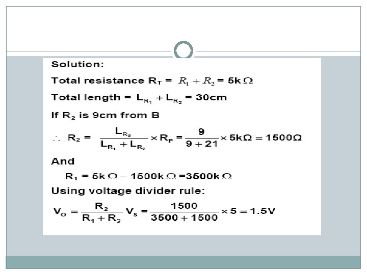
Example: A displacement transducer with a shaft stroke of 30 cm is applied to the circuit. The total resistance of the potentiometer is 5 k Ω. The applied voltage VS is 5 V. Calculate the output voltage when the wiper is 9 cm from B.
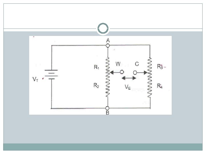
Example: A potentiometer transducer with a shaft stroke of 8. 0 cm is used in circuit below. The applied voltage is 10 V. The total resistance of potentiometer R 1 and R 2 is 6 kΩ. The total resistance of the potentiometer R 3 and R 4 is 4 kΩ. The initial position to be used as a reference point is set such that R 1 is 4. 5 cm and R 3 is 3. 5 cm of the shaft stroke length (from point A). i. Calculate the values of R 1, R 3 and VE at initial position ii. Calculate the displacements of potentiometer R 3 and R 4 in the case that VE =0. Then identify the direction of the displacement
"Strive always to excel in virtue and truth. " (Bukhari)
Exercise: A displacement transducer with a shaft of 2. 0 mm is used in the circuit as shown in figure below. The total resistance of the potentiometer R 1 and R 2 is 5000Ω and the applied voltage is 5. 0 V. The total resistance of the potentiometer R 3 and R 4 is also 5000Ω. The initial position to be used as reference point is set such that R 1 = R 2 (i. e. when the shaft is at mid-stroke). Initially, potentiometer R 3 and R 4 is adjusted so that the bridge is balanced (i. e. VE = 0). Assuming the shaft of the potentiometer R 3 and R 4 will be moved 0. 5 mm towards A, what is the value of VE?
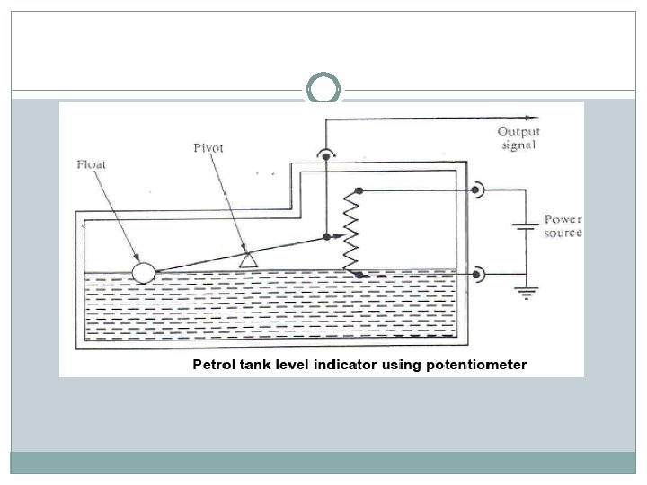
Potentiometer senses displacement by means of sensing shaft, which is mechanically connected to the point or objects whose displacement, is to be measured. Example: Petrol-tank level indicator. In this case, potentiometer is used to indicate/sense the petrol level in a tank as shown in Figure below. The output signal (voltage) is proportional to the petrol level, v
Advantages & Disadvantages of Potentiometer
Capacitive transducer A capacitor consists of two parallel plates separated by an air space or by a dieletric (insulating material) as shown in figure below The capacitance of the pair of plates is measure of the amount of charge that can be transferred before a certain voltage is reached. If the capacitance is large, more charge is needed to establish a given voltage difference
The equation for capacitance of a parallel plate capacitor is given by: -
the capacitive transducer works on the principle of changing of capacitance which may caused by:
Advantages : 1. Required extremely small forces to operate them and hence are very useful for use in small systems. 2. Extremely sensitive. 3. A good frequency response as high as 50 k. Hz and useful for dynamic studies. 4. High input impedance therefore the loading effects are minimum. 5. The force requirements is very small and therefore require small power to operates them Disadvantages: 1. The metallic parts of the transducer must be insulated from each other in order to reduce the effects of stray capacitance, the frames must be earthen. 2. The output impedance of the capacitive transducers tends to be high on account of their small capacitance value this leads to loading effects.
Uses of Capacitive Transducer 1. It can be used for measurement of both linear and angular displacements. 2. It can be used for measurement of force and pressure. The force and pressure to be measured are first converted to displacement which caused a change in capacitance. 3. It can be used for measurement of humidity in gases since the dielectric constant of gases changes with change in humidity thereby producing a change in capacitance. 4. It is commonly used in conjunction with mechanical modifiers for measurement of volume, density, liquid level, weight and etc. "Strive always to excel in virtue and truth. " (Bukhari)
Capacitive sensor is used to detect the presence of boxes on the conveyor belt
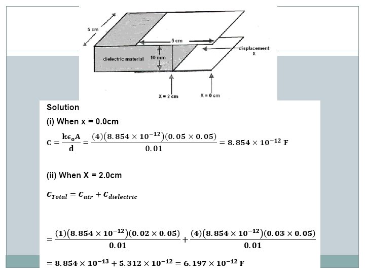
Example: A capacitive transducer is used for the measurement of linear displacement, X, as shown in below. The parallel plate has a dimension of 5. 0 cm X 5. 0 cm and is separated by a distance of 1. 0 cm. The space between the plates is filled with a dielectric material of 1. 0 cm thick, which has a dielectric constant of 4. 0. If the dielectric constant for air is 1. 0 cm, determine the value of the capacitance when x is equal to: (i) 0. 0 cm (ii) 2. 0 cm
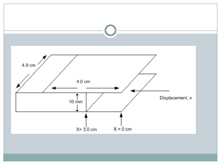
Exercise: Figure below shows a capacitive transducer used for measurement of linear displacement, x. the parallel plates have a dimension of (4. 0 cm x 4. 0 cm) and separated by a distance of 10 mm. the space between plates is filled with a dielectric material with constant of 3. 0. If the dielectric constant for air is 1. 0, determine the value of the capacitance when x is equal to: i) 0. 0 cm ii) 2. 0 cm iii) 4. 0 cm What is the effect of capacitance when the displacement of dielectric is increased? Given εo = 8. 854 x 10 -12 F/m.
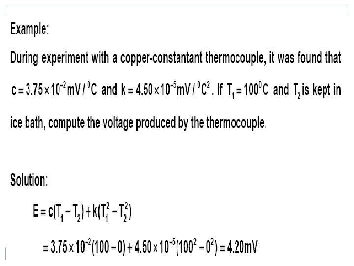
Thermocouple -thermal transducer. It consists of a pair of wire made of different metals that joined together at one end as shown in below. When there is a temperature difference between the two ends of wire, a voltage will be produced between the two wires – Seeback effect
The magnitude of voltage depends on : i) the materials used for the wires ii) the temperature difference between the joined ends and the other ends.
The voltage of thermocouple is given as
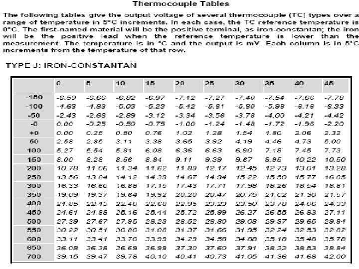
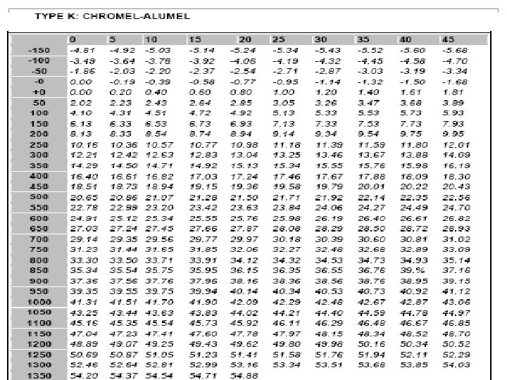
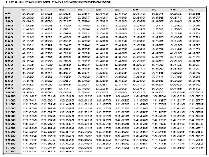
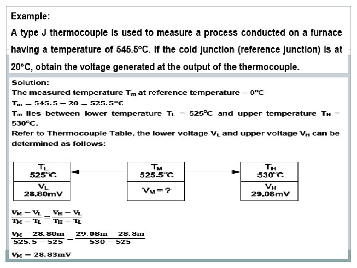
Normally the cold / reference temperature is set to 0 o. C as shown in figure below: Cold junction compensation Thermocouple tables give the relationship between the voltage for a particular type of thermocouple and the measured temperature when the reference junction is at a particular reference temperature
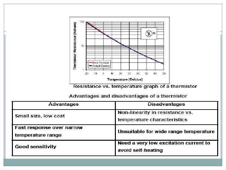
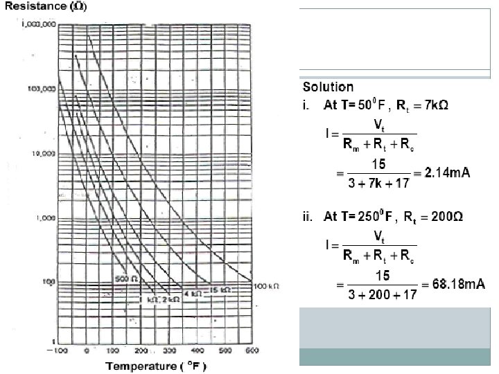
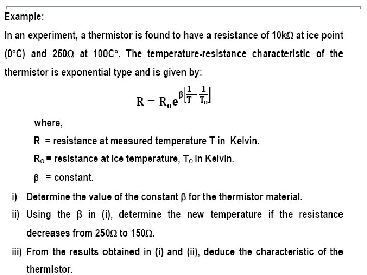
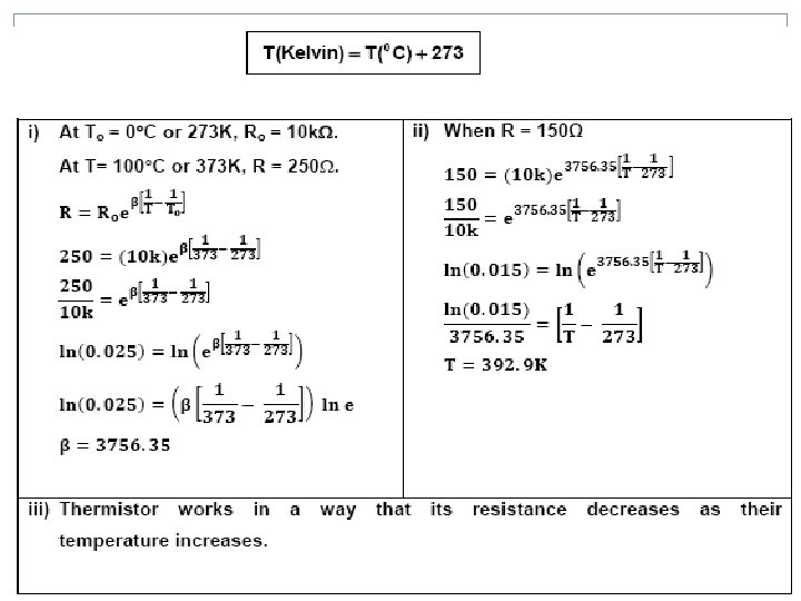
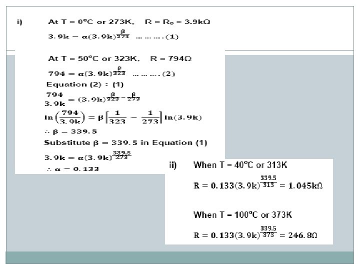
Thermistors - THERMally sensitive res. ISTOR are non-metallic resistors(semiconductor material) made by sintering mixtures of metallic oxides such as manganese, nickel, cobalt, copper and uranium. Thermistor - type of resistance thermometer, uses the change in the electrical resistance to determine the temperature. Thermistors have a Negative Temperature Coefficient (NTC) – resistance decrease as temperature rises as shown in below.
"Strive always to excel in virtue and truth. " (Bukhari)
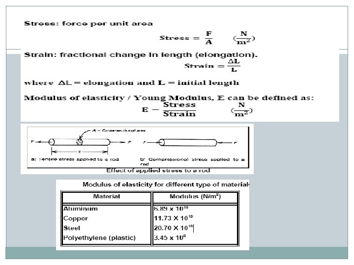
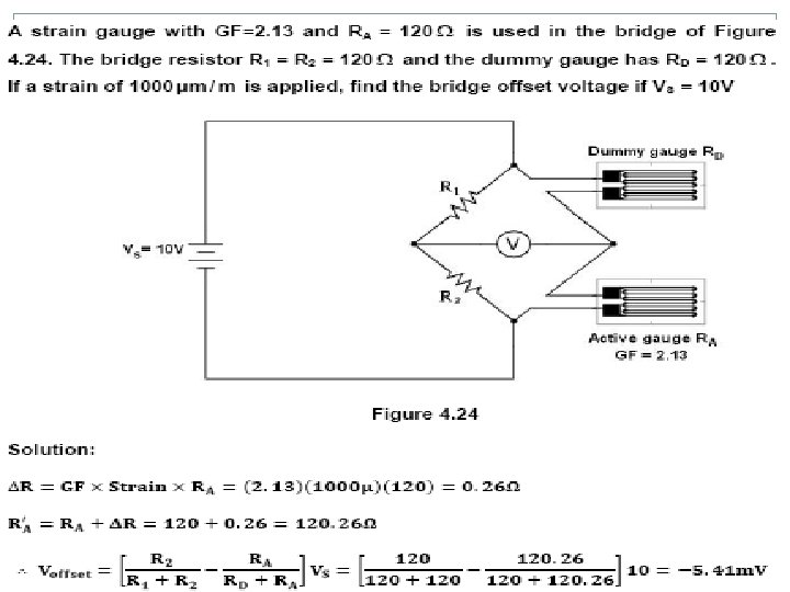
Strain gauge - passive transducer that uses the variation in electrical resistance in wires to sense the strain produced by force on wires. It is used for measuring weight, pressure, mechanical force and displacement. A bonded strain gauge consists of a fine wire looped back and forth on a mounting plate which is usually cemented to the member undergoing stress as shown below
Bonded strain gauge
Strain gauge is generally uses as one arm of a bridge is shown Figure below. This method is capable to measure the change in resistance when the wire is under strain.
In some cases, strain gauges are used in pairs (active gauge and dummy gauge) to provide temperature compensation as in Figure below. However, only the active gauge will respond to stress. The dummy gauge is mounted in an insensitive orientation to provide some compensation for temperature effects.
- Strain Gauge - Strain gauge 1 is stretch Strain gauge 2 is compressed
- Strain Gauge APPLICATION OF STRAIN GAUGE
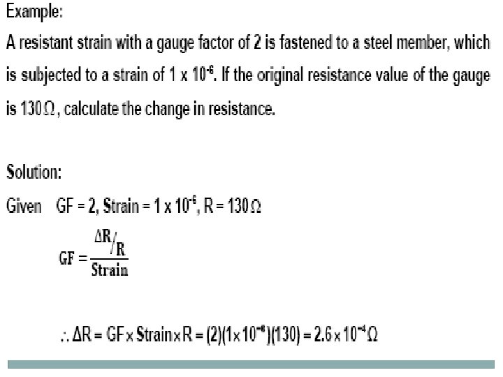
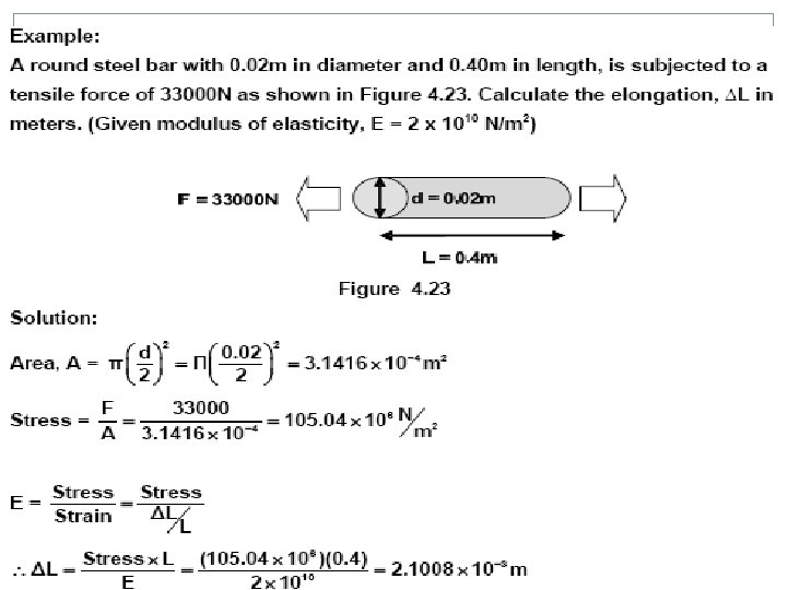
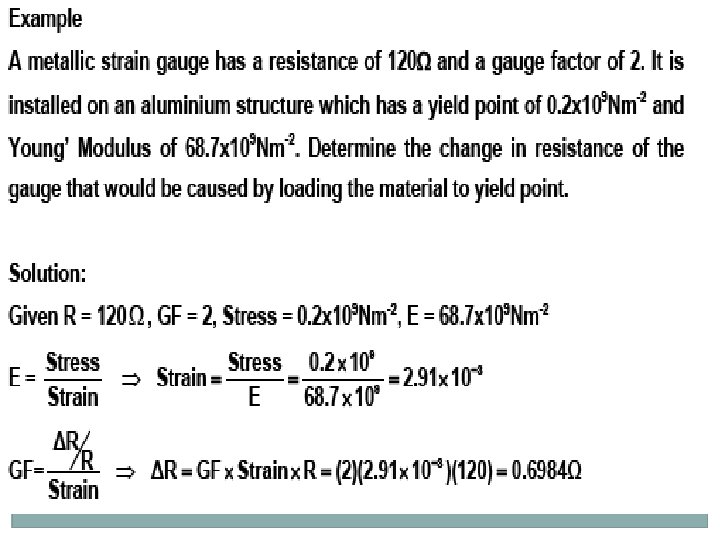
- Strain Gauge EXAMPLE OF STRAIN GAUGE
The strain will cause: i) The change in length ΔL ii) The change in gauge resistance ΔR "Strive always to excel in virtue and truth. " (Bukhari)
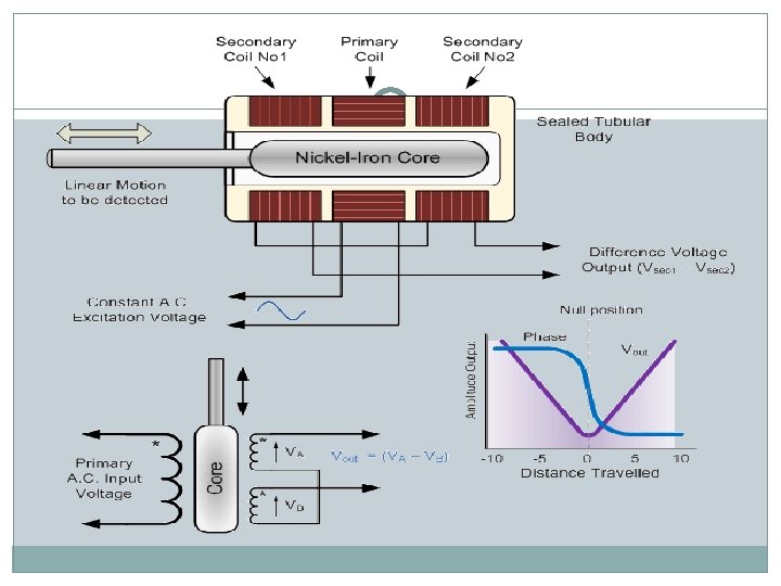
Linear Variable Differential Transformer -Inductive position sensor When an AC excitation signal is applied to the Primary Coil (P), voltages are induced in the two Secondary Coils (S). The MAGNETIC CORE inside the COIL WINDING ASSEMBLY provides the magnetic flux path linking the Primary and secondary Coils. Since the two voltages are of opposite polarity, the Secondary Coils are connected series opposing in the center, or Null Position. The output voltages are equal and opposite in polarity and, therefore, the output voltage is zero. The Null Position of an LVDT is extremely stable and repeatable. When the MAGNETIC CORE is displaced from the Null Position, an electromagnetic imbalance occurs. This imbalance generates a differential AC output voltage across the Secondary Coils which is linearly proportional to the direction and magnitude of the displacement.
As shown in the figure, when the MAGNETIC CORE is moved from the Null Position, the induced voltage in the Secondary Coil, toward which the Core is moved, increases while the induced voltage in the opposite Secondary Coil decreases. LVDTs possess the inherent ruggedness and durability of a transformer and truly provide infinite resolution in all types of environments. As a result of the superior reliability and accuracy of LVDTs, they are the ideal choice for linear motion control.
Advantages -LVDT compared to a resistive potentiometer are that its linearity, that is its voltage output to displacement is excellent, very good accuracy, good resolution, high sensitivity as well as frictionless operation and is sealed against hostile environments
Example An AC LVDT has the following data. Input = 6. 3 V, output=5. 2 V range +/- 0. 5 in. Determine: a) Calculate the output voltage vs core position for a core movement going from +0. 45 in to -0. 30 in. b)The output voltage when the core is -0. 25 in from the centre. Solution a)0. 5 in core displacement produces 5. 2 V, therefore a 0. 45 in core movement produces(0. 45 x 5. 2)/0. 5 = 4. 68 V At -0. 30 in core movement produces (-0. 30 x-5. 2)/(-0. 5) = -3. 12 V b) -0. 25 in core movement produces (-0. 25 x-5. 2)/(-0. 5) = -2. 6 V
Resistive Temperature Detectors (RTD). RTD's are precision temperature sensors made from high-purity conducting metals such as platinum, copper or nickel wound into a coil and whose electrical resistance changes as a function of temperature, similar to that of thermistor Also available are thin-film RTD's. These devices have a thin film of platinum paste is deposited onto a white ceramic substrate. They have poor sensitivity, that is a change in temperature only produces a very small output change for example, 1Ω/o. C.
RTD is a resistive device - need to pass a current through them and monitor the resulting voltage. Any variation in resistance due to self heat of the resistive wires as the current flows through it, I 2 R, (Ohms Law) causes an error in the readings. To avoid - RTD is usually connected into a Whetstone Bridge network which has additional connecting wires for leadcompensation and/or connection to a constant current source. Relationship between temperature and resistance of conductors : • Rt=Rref(1+αΔt) Rt – resistance of conductor at temperature t degree Rref – resistance of the reference temperture, usually 0 degree α – temperature coefficient of resistance Δt – difference between operating and reference temperature
Exercise A platinum resistance thermometer has resistance of 180Ω at 20 degree Celsius. Calculate its resistance at 60 degree Celsius. (α 20 = 0. 00392) ans: 151. 78 Ω A platinum resistance thermometer has a resistance of 100 Ω at 23 degree Celsius. Find its resistance at 50 degree Celsius. The resistance temperature coefficient of platinum is 0. 00392 Ω/ Ω celsius. If thermometer has a resistance of 200 Ω, calculate the value of temperature.