
EENG 447 Digital IC Design Dr Grta Yemiciolu

- Slides: 85
EENG 447 Digital IC Design Dr. Gürtaç Yemişcioğlu
2 CHAPTER #2 CAD TOOLS & DESIGN ENTRY VHDL I 0 4 / 0 3 / 2 0 2 1 D i g i t a l I C D e s i g n
3 VHDL I About • VHDL is a hardware description language. • It describes the behavior of an electronic circuit or system, from which the physical circuit or system can then be implemented. • VHDL stands for VHSIC (Very High Speed Integrated Circuit) Hardware Description Language. 0 4 / 0 3 / 2 0 2 1 D i g i t a l I C D e s i g n
4 VHDL I About • VHDL was the original and first hardware description language to be standardized by the Institute of Electrical and Electronics Engineer, through the IEEE 1076 standard. • An additional standard, the IEEE 1164 was later added to introduce a multivalued logic system. 0 4 / 0 3 / 2 0 2 1 D i g i t a l I C D e s i g n
5 VHDL I About • VHDL is intended for circuit synthesis as well as circuit simulation. • However, though VHDL is fully simulate able, not all constructs are synthesizable. • Fundamental motivation to use VHDL (or Verilog) is that VHDL is a standard, technology/vendor independent language, and is therefore portable and reusable. 0 4 / 0 3 / 2 0 2 1 D i g i t a l I C D e s i g n
6 VHDL I About • Two main immediate applications of VHDL are in the field of Programmable Logic Devices (CPLDs - Complex Programmable Logic Devices and FPGAs Field Programmable Gate Arrays) and in the field of ASICs (Application Specific Integrated Circuits). • Currently many complex commercial chips are designed using such an approach. 0 4 / 0 3 / 2 0 2 1 D i g i t a l I C D e s i g n
7 VHDL I About • Contrary to regular computer programs which are sequential, its statements are inherently concurrent (parallel). • For that reason, VHDL is usually referred to as a code rather than a program. • In VHDL, only statements placed inside a PROCESS, FUNCTION or PROCEDURE are executed sequentially. 0 4 / 0 3 / 2 0 2 1 D i g i t a l I C D e s i g n
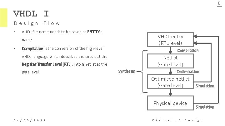
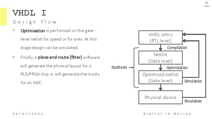
8 VHDL I Design Flow • VHDL file name needs to be saved as ENTITY’s VHDL entry (RTL level) name. • Compilation is the conversion of the high-level Compilation VHDL language which describes the circuit at the Netlist (Gate level) Register Transfer Level (RTL), into a netlist at the gate level. Synthesis Optimisation Optimised netlist (Gate level) Physical device 0 4 / 0 3 / 2 0 2 1 D i g i t a l I C Simulation D e s i g n
9 VHDL I Design Flow • Optimisation is performed on the gate- VHDL entry (RTL level) level netlist for speed or for area. At this stage design can be simulated. • Compilation Netlist (Gate level) Finally, a place-and-route (fitter) software will generate the physical layout for a PLD/FPGA chip or will generate the masks for an ASIC. Synthesis Optimisation Optimised netlist (Gate level) Physical device 0 4 / 0 3 / 2 0 2 1 D i g i t a l I C Simulation D e s i g n
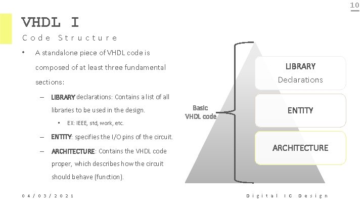
10 VHDL I Code Structure • A standalone piece of VHDL code is LIBRARY Declarations composed of at least three fundamental sections: – LIBRARY declarations: Contains a list of all libraries to be used in the design. • EX: IEEE, std, work, etc. Basic VHDL code ENTITY – ENTITY: specifies the I/O pins of the circuit. – ARCHITECTURE: Contains the VHDL code ARCHITECTURE proper, which describes how the circuit should behave (function). 0 4 / 0 3 / 2 0 2 1 D i g i t a l I C D e s i g n
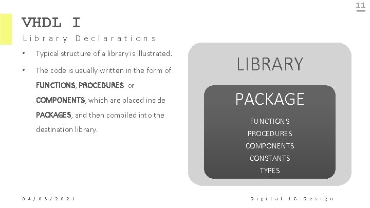
11 VHDL I Library Declarations • Typical structure of a library is illustrated. • The code is usually written in the form of FUNCTIONS, PROCEDURES or COMPONENTS, which are placed inside PACKAGES, and then compiled into the destination library. 0 4 / 0 3 / 2 0 2 1 LIBRARY PACKAGE FUNCTIONS PROCEDURES COMPONENTS CONSTANTS TYPES D i g i t a l I C D e s i g n
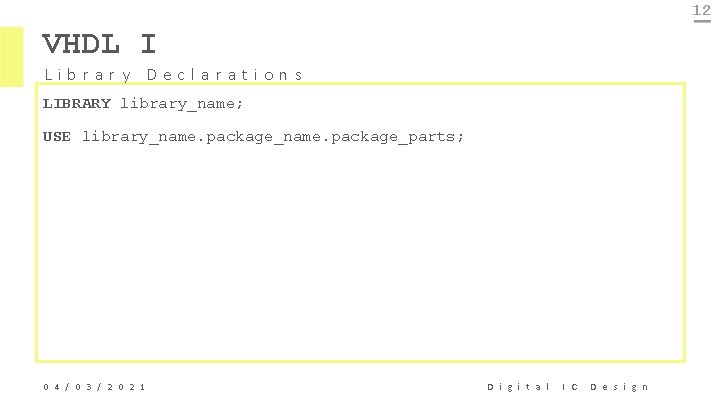
12 VHDL I Library Declarations LIBRARY library_name; USE library_name. package_parts; 0 4 / 0 3 / 2 0 2 1 D i g i t a l I C D e s i g n
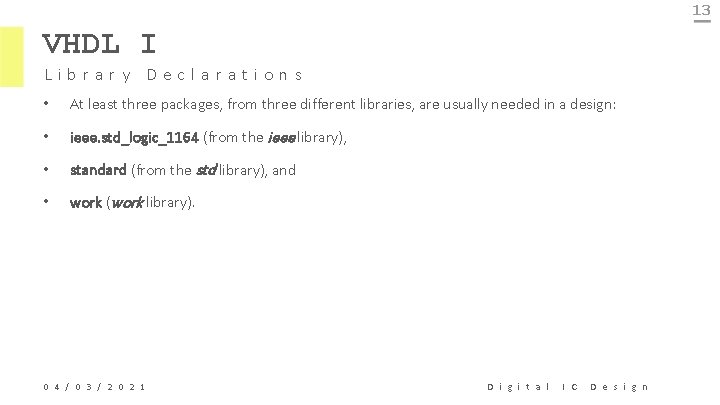
13 VHDL I Library Declarations • At least three packages, from three different libraries, are usually needed in a design: • ieee. std_logic_1164 (from the ieee library), • standard (from the std library), and • work (work library). 0 4 / 0 3 / 2 0 2 1 D i g i t a l I C D e s i g n
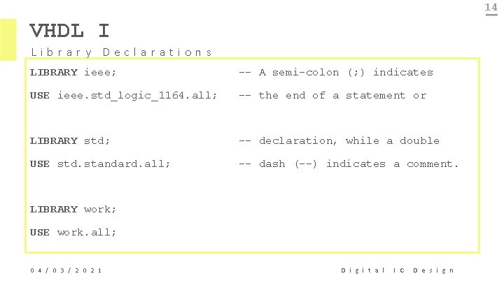
14 VHDL I Library Declarations LIBRARY ieee; -- A semi-colon (; ) indicates USE ieee. std_logic_1164. all; -- the end of a statement or LIBRARY std; -- declaration, while a double USE std. standard. all; -- dash (--) indicates a comment. LIBRARY work; USE work. all; 0 4 / 0 3 / 2 0 2 1 D i g i t a l I C D e s i g n
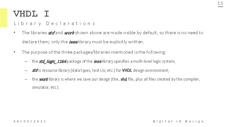
15 VHDL I Library Declarations • The libraries std and work shown above are made visible by default, so there is no need to declare them; only the ieee library must be explicitly written. • The purpose of the three packages/libraries mentioned is the following: – the std_logic_1164 package of the ieee library specifies a multi-level logic system; – std is resource library (data types, text i/o, etc. ) for VHDL design environment; – the work library is where we save our design (the. vhd file, plus all files created by the compiler, simulator, etc. ) 0 4 / 0 3 / 2 0 2 1 D i g i t a l I C D e s i g n
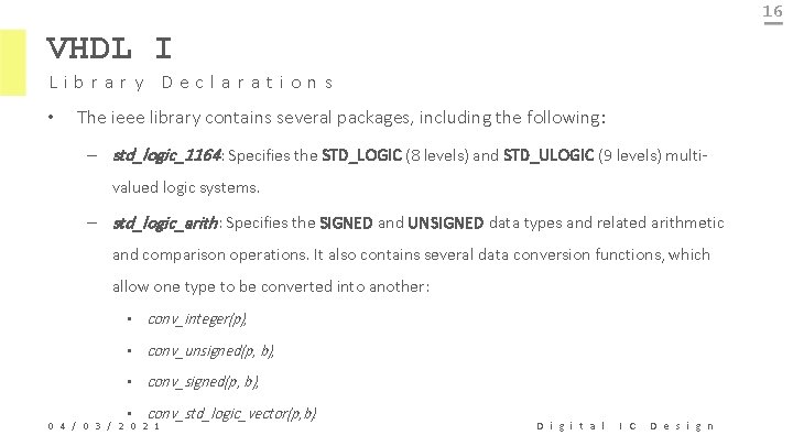
16 VHDL I Library Declarations • The ieee library contains several packages, including the following: – std_logic_1164: Specifies the STD_LOGIC (8 levels) and STD_ULOGIC (9 levels) multivalued logic systems. – std_logic_arith: Specifies the SIGNED and UNSIGNED data types and related arithmetic and comparison operations. It also contains several data conversion functions, which allow one type to be converted into another: • conv_integer(p), • conv_unsigned(p, b), • conv_std_logic_vector(p, b). 0 4 / 0 3 / 2 0 2 1 D i g i t a l I C D e s i g n
17 VHDL I Library Declarations • std_logic_signed: Contains functions that allow operation with STD_LOGIC_VECTOR data to be performed as if the data were of type SIGNED. • std_logic_unsigned: Contains functions that allow operation with STD_LOGIC_VECTOR data to be performed as if the data were of type UNSIGNED. 0 4 / 0 3 / 2 0 2 1 D i g i t a l I C D e s i g n
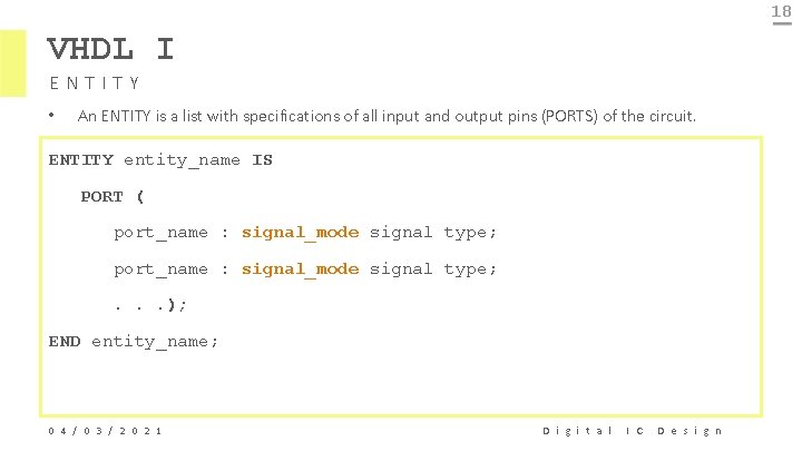
18 VHDL I ENTITY • An ENTITY is a list with specifications of all input and output pins (PORTS) of the circuit. ENTITY entity_name IS PORT ( port_name : signal_mode signal type; . . . ); END entity_name; 0 4 / 0 3 / 2 0 2 1 D i g i t a l I C D e s i g n
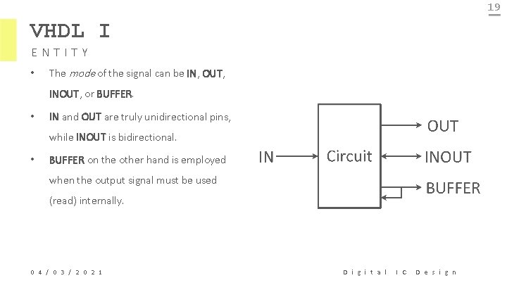
19 VHDL I ENTITY • The mode of the signal can be IN, OUT, INOUT, or BUFFER. • IN and OUT are truly unidirectional pins, while INOUT is bidirectional. • BUFFER on the other hand is employed when the output signal must be used (read) internally. 0 4 / 0 3 / 2 0 2 1 D i g i t a l I C D e s i g n
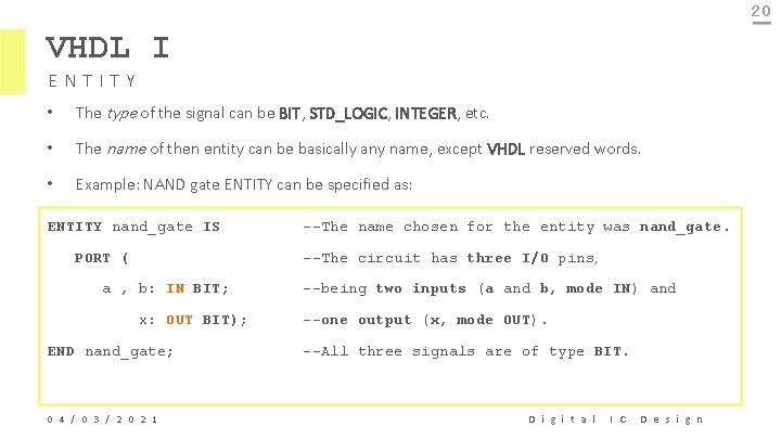
20 VHDL I ENTITY • The type of the signal can be BIT, STD_LOGIC, INTEGER, etc. • The name of then entity can be basically any name, except VHDL reserved words. • Example: NAND gate ENTITY can be specified as: ENTITY nand_gate IS PORT ( --The name chosen for the entity was nand_gate. --The circuit has three I/O pins, a , b: IN BIT; x: OUT BIT); END nand_gate; 0 4 / 0 3 / 2 0 2 1 --being two inputs (a and b, mode IN) and --one output (x, mode OUT). --All three signals are of type BIT. D i g i t a l I C D e s i g n
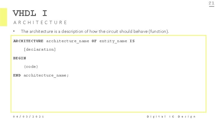
21 VHDL I ARCHITECTURE • The architecture is a description of how the circuit should behave (function). ARCHITECTURE architecture_name OF entity_name IS [declaration] BEGIN (code) END architecture_name; 0 4 / 0 3 / 2 0 2 1 D i g i t a l I C D e s i g n
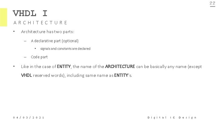
22 VHDL I ARCHITECTURE • Architecture has two parts: – A declarative part (optional) • signals and constants are declared – Code part • Like in the case of ENTITY, the name of the ARCHITECTURE can be basically any name (except VHDL reserved words), including same name as ENTITY’s. 0 4 / 0 3 / 2 0 2 1 D i g i t a l I C D e s i g n
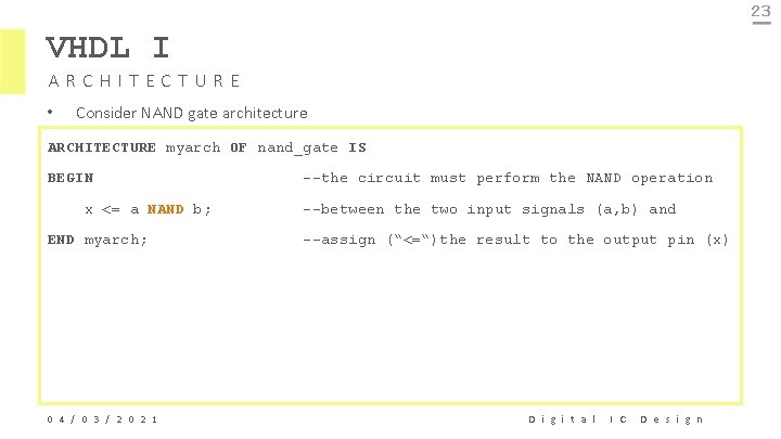
23 VHDL I ARCHITECTURE • Consider NAND gate architecture ARCHITECTURE myarch OF nand_gate IS BEGIN x <= a NAND b; END myarch; 0 4 / 0 3 / 2 0 2 1 --the circuit must perform the NAND operation --between the two input signals (a, b) and --assign (“<=“)the result to the output pin (x) D i g i t a l I C D e s i g n
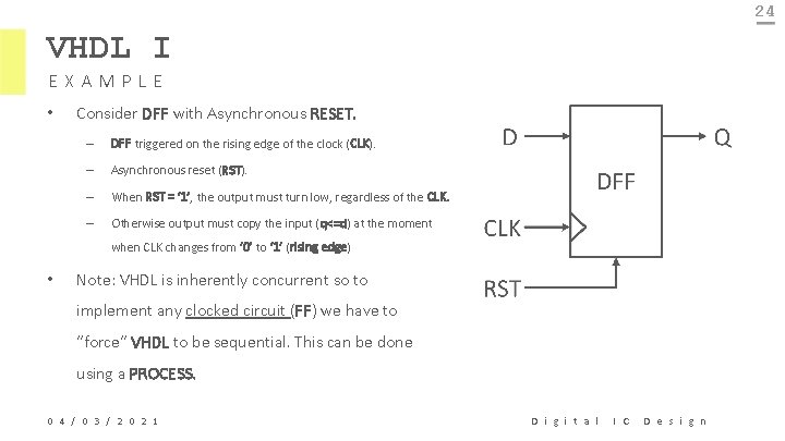
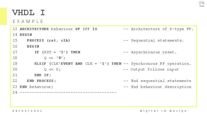
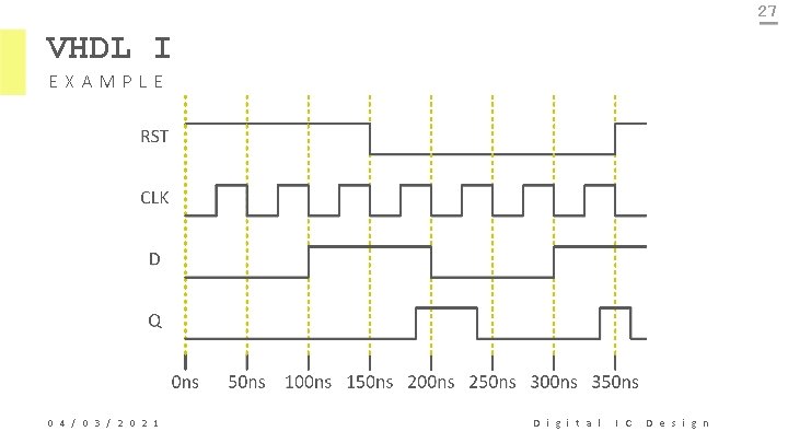
24 VHDL I EXAMPLE • Consider DFF with Asynchronous RESET. – DFF triggered on the rising edge of the clock (CLK). – Asynchronous reset (RST). – When RST = ‘ 1’, the output must turn low, regardless of the CLK. – Otherwise output must copy the input (q<=d) at the moment when CLK changes from ‘ 0’ to ‘ 1’ (rising edge) • Note: VHDL is inherently concurrent so to implement any clocked circuit (FF) we have to “force” VHDL to be sequential. This can be done using a PROCESS. 0 4 / 0 3 / 2 0 2 1 D i g i t a l I C D e s i g n
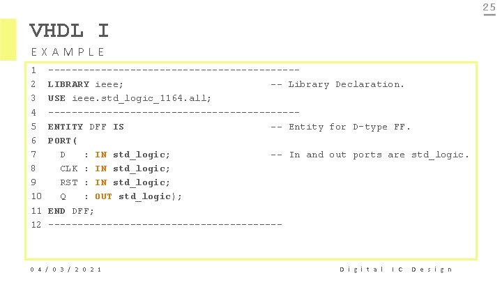
25 VHDL I EXAMPLE 1 2 3 4 5 6 7 8 9 10 11 12 ---------------------LIBRARY ieee; -- Library Declaration. USE ieee. std_logic_1164. all; ---------------------ENTITY DFF IS -- Entity for D-type FF. PORT( D : IN std_logic; -- In and out ports are std_logic. CLK : IN std_logic; RST : IN std_logic; Q : OUT std_logic); END DFF; -------------------- 0 4 / 0 3 / 2 0 2 1 D i g i t a l I C D e s i g n
26 VHDL I EXAMPLE 13 14 15 16 17 18 19 20 21 22 23 24 ARCHITECTURE behaviour OF DFF IS BEGIN PROCESS (rst, clk) BEGIN IF (RST = ‘ 1’) THEN Q <= ‘ 0’; ELSIF (CLK’EVENT AND CLK = ‘ 1’) THEN Q <= D; END IF; END PROCESS; END behaviour; -------------------- 0 4 / 0 3 / 2 0 2 1 -- Architecture of D-type FF. -- Sequential statements. -- Asynchronous reset. -- Synchronous FF operation. -- Output follows input -- End sequential statements -- End behaviour description D i g i t a l I C D e s i g n
27 VHDL I EXAMPLE 0 4 / 0 3 / 2 0 2 1 D i g i t a l I C D e s i g n
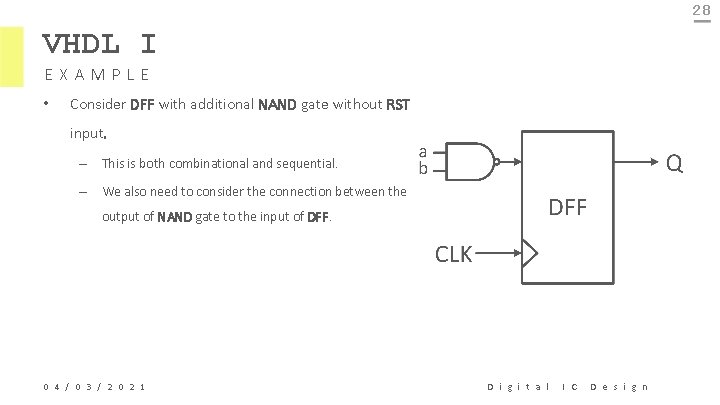
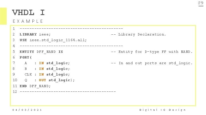
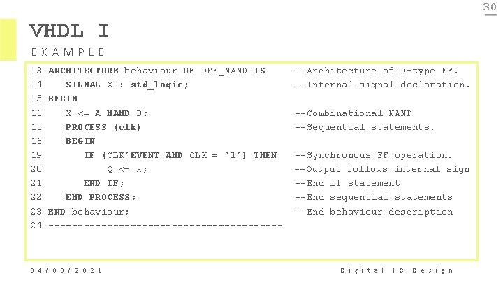
28 VHDL I EXAMPLE • Consider DFF with additional NAND gate without RST input. – This is both combinational and sequential. – We also need to consider the connection between the output of NAND gate to the input of DFF. 0 4 / 0 3 / 2 0 2 1 D i g i t a l I C D e s i g n
29 VHDL I EXAMPLE 1 2 3 4 5 6 7 8 9 10 11 12 ---------------------LIBRARY ieee; -- Library Declaration. USE ieee. std_logic_1164. all; ---------------------ENTITY DFF_NAND IS -- Entity for D-type FF with NAND. PORT( A : IN std_logic; -- In and out ports are std_logic. B : IN std_logic; CLK : IN std_logic; Q : OUT std_logic); END DFF_NAND; -------------------- 0 4 / 0 3 / 2 0 2 1 D i g i t a l I C D e s i g n
30 VHDL I EXAMPLE 13 14 15 16 19 20 21 22 23 24 ARCHITECTURE behaviour OF DFF_NAND IS SIGNAL X : std_logic; BEGIN X <= A NAND B; PROCESS (clk) BEGIN IF (CLK’EVENT AND CLK = ‘ 1’) THEN Q <= x; END IF; END PROCESS; END behaviour; -------------------- 0 4 / 0 3 / 2 0 2 1 --Architecture of D-type FF. --Internal signal declaration. --Combinational NAND --Sequential statements. --Synchronous FF operation. --Output follows internal sign --End if statement --End sequential statements --End behaviour description D i g i t a l I C D e s i g n
31 VHDL I DATA TYPES • In order to write VHDL code efficiently, it is essential to know what data types are allowed, and how to specify and use them. • VHDL contains a series of pre-defined data types, specified through the IEEE 1076 and IEEE 1164 standards. 0 4 / 0 3 / 2 0 2 1 D i g i t a l I C D e s i g n
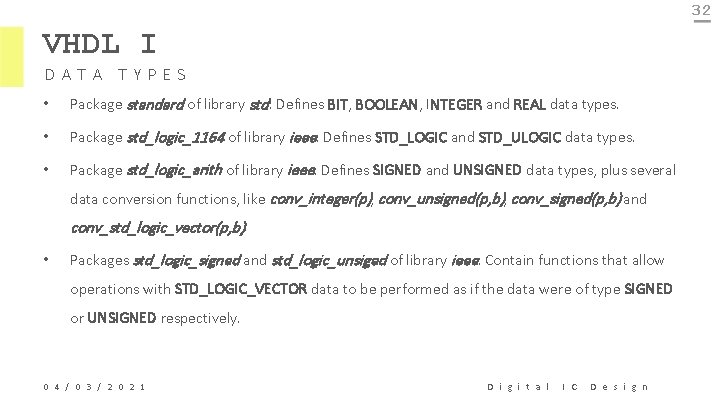
32 VHDL I DATA TYPES • Package standard of library std: Defines BIT, BOOLEAN, INTEGER and REAL data types. • Package std_logic_1164 of library ieee: Defines STD_LOGIC and STD_ULOGIC data types. • Package std_logic_arith of library ieee: Defines SIGNED and UNSIGNED data types, plus several data conversion functions, like conv_integer(p), conv_unsigned(p, b), conv_signed(p, b) and conv_std_logic_vector(p, b). • Packages std_logic_signed and std_logic_unsiged of library ieee: Contain functions that allow operations with STD_LOGIC_VECTOR data to be performed as if the data were of type SIGNED or UNSIGNED respectively. 0 4 / 0 3 / 2 0 2 1 D i g i t a l I C D e s i g n
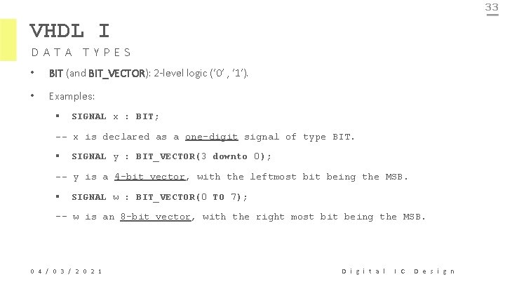
33 VHDL I DATA TYPES • BIT (and BIT_VECTOR): 2 -level logic (‘ 0’ , ‘ 1’). • Examples: § SIGNAL x : BIT; -- x is declared as a one-digit signal of type BIT. § SIGNAL y : BIT_VECTOR(3 downto 0); -- y is a 4 -bit vector, with the leftmost bit being the MSB. § SIGNAL w : BIT_VECTOR(0 TO 7); -- w is an 8 -bit vector, with the right most bit being the MSB. 0 4 / 0 3 / 2 0 2 1 D i g i t a l I C D e s i g n
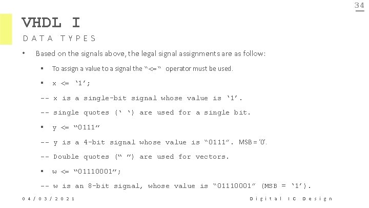
34 VHDL I DATA TYPES • Based on the signals above, the legal signal assignments are as follow: § To assign a value to a signal the “<=“ operator must be used. § x <= ‘ 1’; -- x is a single-bit signal whose value is ‘ 1’. -- single quotes (‘ ‘) are used for a single bit. § y <= “ 0111” -- y is a 4 -bit signal whose value is “ 0111”. MSB = ‘ 0’. -- Double quotes (“ ”) are used for vectors. § w <= “ 01110001”; -- w is an 8 -bit signal, whose value is “ 01110001” (MSB = ‘ 1’). 0 4 / 0 3 / 2 0 2 1 D i g i t a l I C D e s i g n
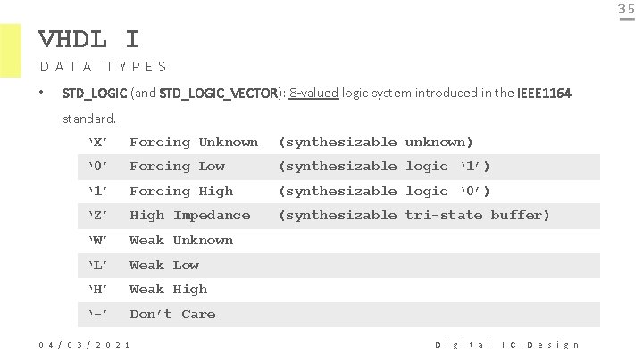
35 VHDL I DATA TYPES • STD_LOGIC (and STD_LOGIC_VECTOR): 8 -valued logic system introduced in the IEEE 1164 standard. ‘X’ Forcing Unknown (synthesizable unknown) ‘ 0’ Forcing Low (synthesizable logic ‘ 1’) ‘ 1’ Forcing High (synthesizable logic ‘ 0’) ‘Z’ High Impedance (synthesizable tri-state buffer) ‘W’ Weak Unknown ‘L’ Weak Low ‘H’ Weak High ‘-’ Don’t Care 0 4 / 0 3 / 2 0 2 1 D i g i t a l I C D e s i g n
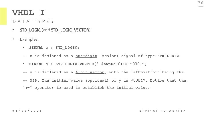
36 VHDL I DATA TYPES • STD_LOGIC (and STD_LOGIC_VECTOR) • Examples: § SIGNAL x : STD_LOGIC; -- x is declared as a one-digit (scalar) signal of type STD_LOGIC. § SIGNAL y : STD_LOGIC_VECTOR(3 downto 0): = “ 0001”; -- y is declared as a 4 -bit vector, with the leftmost bit being the -- MSB. The initial value (optional) of y is “ 0001”. Notice that the “: =“ operator is used to establish the initial value. 0 4 / 0 3 / 2 0 2 1 D i g i t a l I C D e s i g n
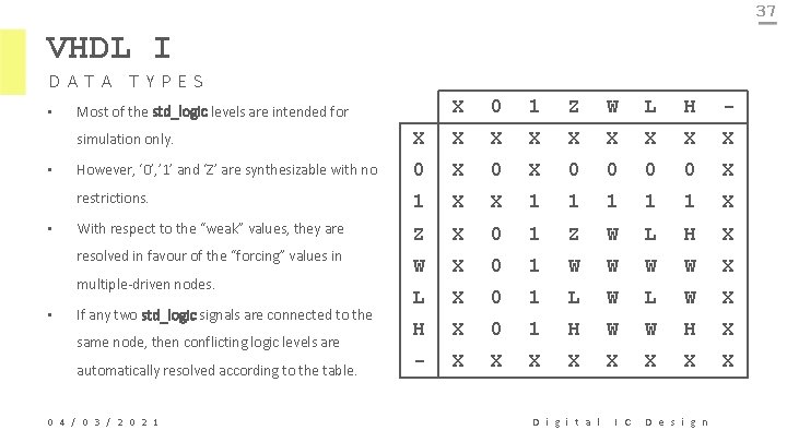
37 VHDL I DATA TYPES • • • Most of the std_logic levels are intended for 0 1 Z W L H - simulation only. X X X X X However, ‘ 0’, ’ 1’ and ‘Z’ are synthesizable with no 0 X 0 0 X restrictions. 1 X X 1 1 1 X With respect to the “weak” values, they are Z X 0 1 Z W L H X W X 0 1 W W X L X 0 1 L W X H X 0 1 H W W H X - X X X X resolved in favour of the “forcing” values in multiple-driven nodes. • X If any two std_logic signals are connected to the same node, then conflicting logic levels are automatically resolved according to the table. 0 4 / 0 3 / 2 0 2 1 D i g i t a l I C D e s i g n
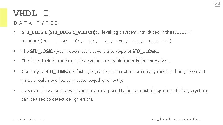
38 VHDL I DATA TYPES • STD_ULOGIC (STD_ULOGIC_VECTOR): 9 -level logic system introduced in the IEEE 1164 standard (‘U’ , ‘X’ ‘ 0’, ‘ 1’, ‘Z’, ‘W’, ‘L’, ‘H’, ‘-’). • The STD_LOGIC system described above is a subtype of STD_ULOGIC. • The latter includes and extra logic value ‘U’, which stands for unresolved. • Contrary to STD_LOGIC conflicting logic levels are not automatically resolved here, so output wires should never be connected together directly. • However, if two output wires are never supposed to be connected together, this logic system can be used to detect design errors. 0 4 / 0 3 / 2 0 2 1 D i g i t a l I C D e s i g n
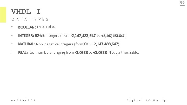
39 VHDL I DATA TYPES • BOOLEAN: True, False. • INTEGER: 32 -bit integers (from -2, 147, 483, 647 to +2, 147, 483, 647). • NATURAL: Non-negative integers (from 0 to +2, 147, 483, 647). • REAL: Real numbers ranging from -1. 0 E 38 to +1. 0 E 38. Not synthesizable. 0 4 / 0 3 / 2 0 2 1 D i g i t a l I C D e s i g n
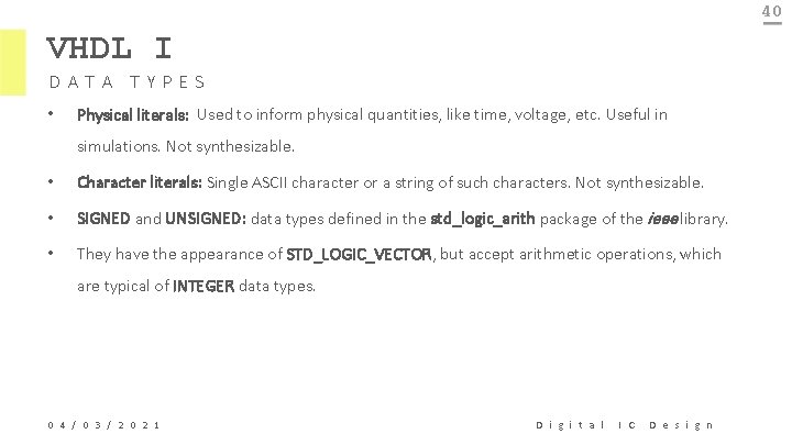
40 VHDL I DATA TYPES • Physical literals: Used to inform physical quantities, like time, voltage, etc. Useful in simulations. Not synthesizable. • Character literals: Single ASCII character or a string of such characters. Not synthesizable. • SIGNED and UNSIGNED: data types defined in the std_logic_arith package of the ieee library. • They have the appearance of STD_LOGIC_VECTOR, but accept arithmetic operations, which are typical of INTEGER data types. 0 4 / 0 3 / 2 0 2 1 D i g i t a l I C D e s i g n
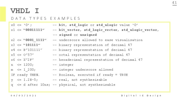
41 VHDL I DATA TYPES EXAMPLES x 0 <= ‘ 0’; x 1 <= “ 00011111” x 2 x 3 x 4 x 5 x 6 n m IF y q ---<= “ 0001_1111” -– <= “ 101111” -<= B” 101111” -<= O” 57” -<= X” 2 F” -<= 1200; -<= 1_200; -ready THEN… -<= 1. 2 E-5; -<= d after 10 ns; -- 0 4 / 0 3 / 2 0 2 1 bit, std_logic or std_ulogic value ‘ 0’ bit_vector, std_logic_vector, std_ulogic_vector, signed or unsigned underscore allowed to ease visualisation binary representation of decimal 47 octal representation of decimal 47 hexadecimal representation of decimal 47 integer underscore allowed Boolean, executed if ready = TRUE real, not synthesisable physical, not synthesisable D i g i t a l I C D e s i g n
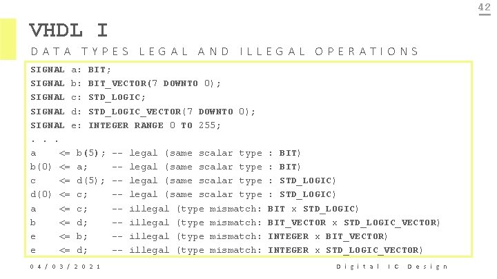
42 VHDL I DATA TYPES LEGAL AND ILLEGAL OPERATIONS SIGNAL a: BIT; SIGNAL b: BIT_VECTOR(7 DOWNTO 0); SIGNAL c: STD_LOGIC; SIGNAL d: STD_LOGIC_VECTOR(7 DOWNTO 0); SIGNAL e: INTEGER RANGE 0 TO 255; . . . a <= b(5); -- legal (same scalar type b(0) <= a; -- legal (same scalar type c <= d(5); -- legal (same scalar type d(0) <= c; -- legal (same scalar type a <= c; -- illegal (type mismatch: b <= d; -- illegal (type mismatch: e <= b; -- illegal (type mismatch: e <= d; -- illegal (type mismatch: 0 4 / 0 3 / 2 0 2 1 : BIT) : STD_LOGIC) BIT x STD_LOGIC) BIT_VECTOR x STD_LOGIC_VECTOR) INTEGER x BIT_VECTOR) INTEGER x STD_LOGIC_VECTOR) D i g i t a l I C D e s i g n
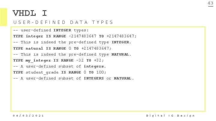
43 VHDL I USER-DEFINED DATA TYPES -- user-defined INTEGER types: TYPE integer IS RANGE -2147483647 TO +2147483647; -- This is indeed the pre-defined type INTEGER. TYPE natural IS RANGE 0 TO +2147483647; -- This is indeed the pre-defined type NATURAL. TYPE my_integer IS RANGE -32 TO +32; -- A user-defined subset of integers. TYPE student_grade IS RANGE 0 TO 100; -- A user-defined subset of INTEGERS or NATURAL. 0 4 / 0 3 / 2 0 2 1 D i g i t a l I C D e s i g n
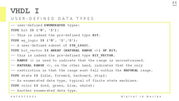
44 VHDL I USER-DEFINED DATA TYPES -- user-defined ENUMERATED types: TYPE bit IS (‘ 0’, ‘ 1’); -- This is indeed the pre-defined type BIT. TYPE my_logic IS (‘ 0’, ‘ 1’, ’Z’); -- A user-defined subset of STD_LOGIC. TYPE bit_vector IS ARRAY (NATURAL RANGE <>) OF BIT; -- this is indeed the pre-defined type BIT_VECTOR. -- RANGE <> is used to indicate that the range is unconstrained. -- NATURAL RANGE <>, on the other hand, indicates that the only -- restriction is that the range must fall within the NATURAL range. TYPE state IS (idle, forward, backward, stop); -- An enumerated data type, typical of finite state machines. TYPE color IS (red, green, blue, white); -- Another enumerated data type. 0 4 / 0 3 / 2 0 2 1 D i g i t a l I C D e s i g n
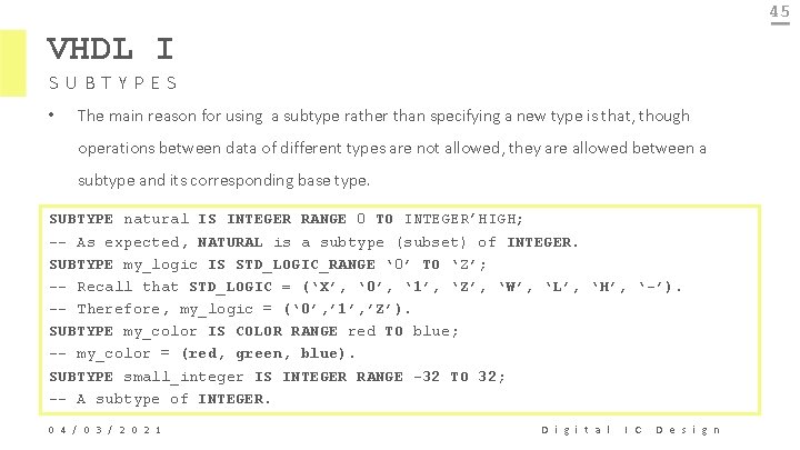
45 VHDL I SUBTYPES • The main reason for using a subtype rather than specifying a new type is that, though operations between data of different types are not allowed, they are allowed between a subtype and its corresponding base type. SUBTYPE natural IS INTEGER RANGE 0 TO INTEGER’HIGH; -- As expected, NATURAL is a subtype (subset) of INTEGER. SUBTYPE my_logic IS STD_LOGIC_RANGE ‘ 0’ TO ‘Z’; -- Recall that STD_LOGIC = (‘X’, ‘ 0’, ‘ 1’, ‘Z’, ‘W’, ‘L’, ‘H’, ‘-’). -- Therefore, my_logic = (‘ 0’, ’ 1’, ’Z’). SUBTYPE my_color IS COLOR RANGE red TO blue; -- my_color = (red, green, blue). SUBTYPE small_integer IS INTEGER RANGE -32 TO 32; -- A subtype of INTEGER. 0 4 / 0 3 / 2 0 2 1 D i g i t a l I C D e s i g n
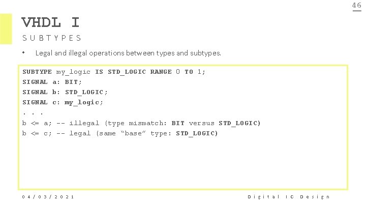
46 VHDL I SUBTYPES • Legal and illegal operations between types and subtypes. SUBTYPE my_logic IS STD_LOGIC RANGE 0 TO 1; SIGNAL a: BIT; SIGNAL b: STD_LOGIC; SIGNAL c: my_logic; . . . b <= a; -- illegal (type mismatch: BIT versus STD_LOGIC) b <= c; -- legal (same “base” type: STD_LOGIC) 0 4 / 0 3 / 2 0 2 1 D i g i t a l I C D e s i g n
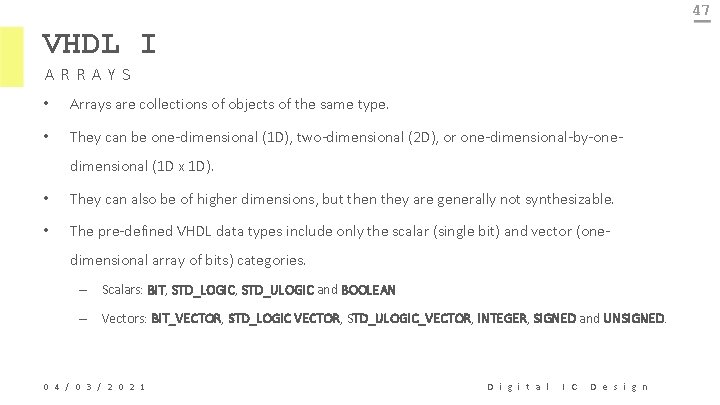
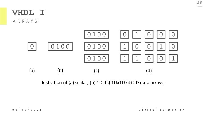
47 VHDL I ARRAYS • Arrays are collections of objects of the same type. • They can be one-dimensional (1 D), two-dimensional (2 D), or one-dimensional-by-onedimensional (1 D x 1 D). • They can also be of higher dimensions, but then they are generally not synthesizable. • The pre-defined VHDL data types include only the scalar (single bit) and vector (onedimensional array of bits) categories. – Scalars: BIT, STD_LOGIC, STD_ULOGIC and BOOLEAN – Vectors: BIT_VECTOR, STD_LOGIC VECTOR, STD_ULOGIC_VECTOR, INTEGER, SIGNED and UNSIGNED. 0 4 / 0 3 / 2 0 2 1 D i g i t a l I C D e s i g n
48 VHDL I ARRAYS 0 4 / 0 3 / 2 0 2 1 D i g i t a l I C D e s i g n
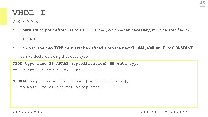
49 VHDL I ARRAYS • There are no pre-defined 2 D or 1 D x 1 D arrays, which when necessary, must be specified by the user. • To do so, the new TYPE must first be defined, then the new SIGNAL, VARIABLE, or CONSTANT can be declared using that data type. TYPE type_name IS ARRAY (specification) OF data_type; -- to specify new array type. SIGNAL signal_name: type_name [: =initial_value]; -- to make use of the new array type. 0 4 / 0 3 / 2 0 2 1 D i g i t a l I C D e s i g n
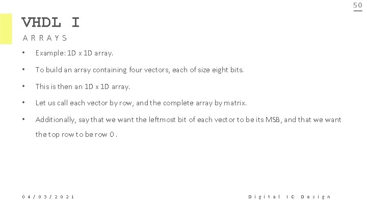
50 VHDL I ARRAYS • Example: 1 D x 1 D array. • To build an array containing four vectors, each of size eight bits. • This is then an 1 D x 1 D array. • Let us call each vector by row, and the complete array by matrix. • Additionally, say that we want the leftmost bit of each vector to be its MSB, and that we want the top row to be row 0. 0 4 / 0 3 / 2 0 2 1 D i g i t a l I C D e s i g n
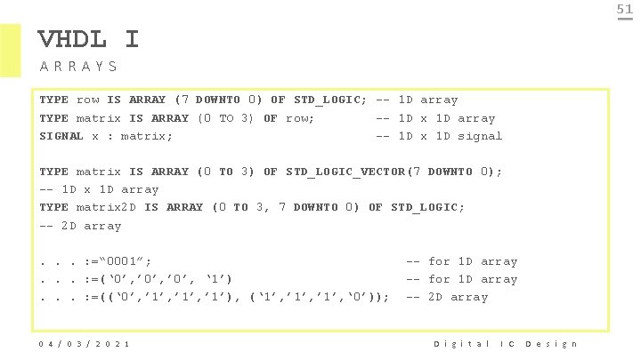
51 VHDL I ARRAYS TYPE row IS ARRAY (7 DOWNTO 0) OF STD_LOGIC; -- 1 D array TYPE matrix IS ARRAY (0 TO 3) OF row; -- 1 D x 1 D array SIGNAL x : matrix; -- 1 D x 1 D signal TYPE matrix IS ARRAY (0 TO 3) OF STD_LOGIC_VECTOR(7 DOWNTO 0); -- 1 D x 1 D array TYPE matrix 2 D IS ARRAY (0 TO 3, 7 DOWNTO 0) OF STD_LOGIC; -- 2 D array. . . : =“ 0001”; . . . : =(‘ 0’, ’ 0’, ‘ 1’). . . : =((‘ 0’, ’ 1’, ’ 1’), (‘ 1’, ’ 1’, ‘ 0’)); 0 4 / 0 3 / 2 0 2 1 -- for 1 D array -- 2 D array D i g i t a l I C D e s i g n
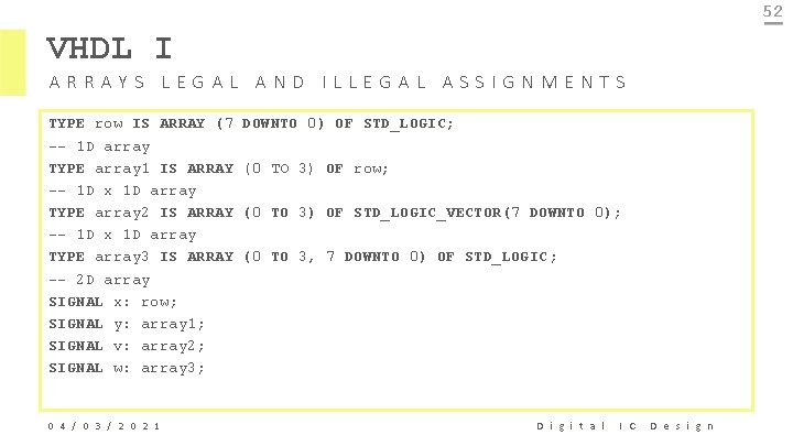
52 VHDL I ARRAYS LEGAL AND ILLEGAL ASSIGNMENTS TYPE row IS ARRAY (7 -- 1 D array TYPE array 1 IS ARRAY -- 1 D x 1 D array TYPE array 2 IS ARRAY -- 1 D x 1 D array TYPE array 3 IS ARRAY -- 2 D array SIGNAL x: row; SIGNAL y: array 1; SIGNAL v: array 2; SIGNAL w: array 3; 0 4 / 0 3 / 2 0 2 1 DOWNTO 0) OF STD_LOGIC; (0 TO 3) OF row; (0 TO 3) OF STD_LOGIC_VECTOR(7 DOWNTO 0); (0 TO 3, 7 DOWNTO 0) OF STD_LOGIC; D i g i t a l I C D e s i g n
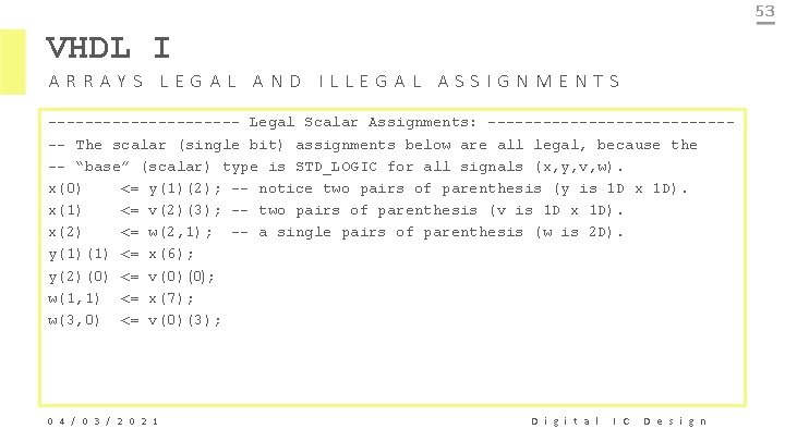
53 VHDL I ARRAYS LEGAL AND ILLEGAL ASSIGNMENTS ----------- Legal Scalar Assignments: -------------- The scalar (single bit) assignments below are all legal, because the -- “base” (scalar) type is STD_LOGIC for all signals (x, y, v, w). x(0) <= y(1)(2); -- notice two pairs of parenthesis (y is 1 D x 1 D). x(1) <= v(2)(3); -- two pairs of parenthesis (v is 1 D x 1 D). x(2) <= w(2, 1); -- a single pairs of parenthesis (w is 2 D). y(1)(1) <= x(6); y(2)(0) <= v(0) (0); w(1, 1) <= x(7); w(3, 0) <= v(0)(3); 0 4 / 0 3 / 2 0 2 1 D i g i t a l I C D e s i g n
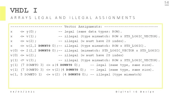
54 VHDL I ARRAYS LEGAL AND ILLEGAL ASSIGNMENTS ------------- Vector Assignments: -------------x <= y(0); -- legal (same data types: ROW). x <= v(1); -- illegal (type mismatch: ROW x STD_LOGIC_VECTOR). x <= w(2); -- illegal (w must have 2 D index). x <= w(2, 2 DOWNTO 0); -- illegal (type mismatch: ROW x STD_LOGIC). v(0) <= 2(2, 2 DOWNTO 0); -- illegal (mismatch: STD_LOGIC_VECTOR x STD_LOGIC) v(0) <= w(2); -- illegal (w must have 2 D index) y(1) <= v(3); -- illegal (type mismatch: ROW x STD_LOGIC_VECTOR). y(1) (7 DOWNTO 3) <= x(4 DOWNTO 0); -- legal (same type, same size). v(1) (7 DOWNTO 3) <= v(2)(4 DOWNTO 0); -- legal (same type, same size). w(1, 5 DOWNTO 1) <= v(2) (4 DOWNTO 0); -- illegal (type mismatch) 0 4 / 0 3 / 2 0 2 1 D i g i t a l I C D e s i g n
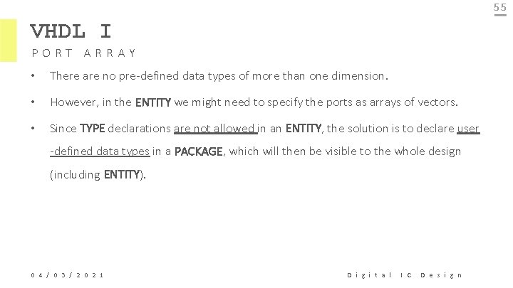
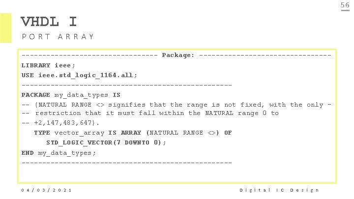
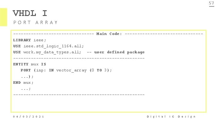
55 VHDL I PORT ARRAY • There are no pre-defined data types of more than one dimension. • However, in the ENTITY we might need to specify the ports as arrays of vectors. • Since TYPE declarations are not allowed in an ENTITY, the solution is to declare user -defined data types in a PACKAGE, which will then be visible to the whole design (including ENTITY). 0 4 / 0 3 / 2 0 2 1 D i g i t a l I C D e s i g n
56 VHDL I PORT ARRAY ----------------- Package: ----------------LIBRARY ieee; USE ieee. std_logic_1164. all; -------------------------PACKAGE my_data_types IS -- (NATURAL RANGE <> signifies that the range is not fixed, with the only -- restriction that it must fall within the NATURAL range 0 to -- +2, 147, 483, 647). TYPE vector_array IS ARRAY (NATURAL RANGE <>) OF STD_LOGIC_VECTOR(7 DOWNTO 0); END my_data_types; -------------------------- 0 4 / 0 3 / 2 0 2 1 D i g i t a l I C D e s i g n
57 VHDL I PORT ARRAY ---------------- Main Code: ---------------LIBRARY ieee; USE ieee. std_logic_1164. all; USE work. my_data_types. all; -- user defined package --------------------------ENTITY mux IS PORT (inp: IN vector_array (0 TO 3); . . . ); END mux; . . . ; -------------------------- 0 4 / 0 3 / 2 0 2 1 D i g i t a l I C D e s i g n
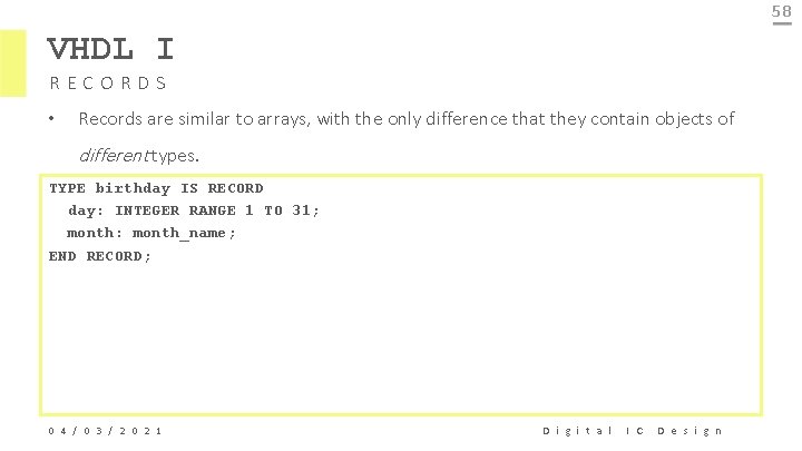
58 VHDL I RECORDS • Records are similar to arrays, with the only difference that they contain objects of different types. TYPE birthday IS RECORD day: INTEGER RANGE 1 TO 31; month: month_name; END RECORD; 0 4 / 0 3 / 2 0 2 1 D i g i t a l I C D e s i g n
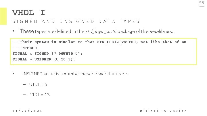
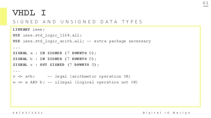
59 VHDL I SIGNED AND UNSIGNED DATA TYPES • These types are defined in the std_logic_arith package of the ieee library. -- Their syntax is similar to that STD_LOGIC_VECTOR, not like that of an -- INTEGER. SIGNAL x: SIGNED (7 DOWNTO 0): SIGNAL y: USIGNED (0 TO 3); • UNSIGNED value is a number never lower than zero. – 0101 = 5 – 1101 = 13 0 4 / 0 3 / 2 0 2 1 D i g i t a l I C D e s i g n
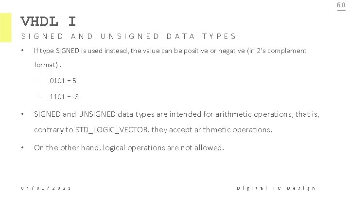
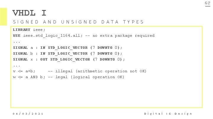
60 VHDL I SIGNED AND UNSIGNED DATA TYPES • If type SIGNED is used instead, the value can be positive or negative (in 2’s complement format). – 0101 = 5 – 1101 = -3 • SIGNED and UNSIGNED data types are intended for arithmetic operations, that is, contrary to STD_LOGIC_VECTOR, they accept arithmetic operations. • On the other hand, logical operations are not allowed. 0 4 / 0 3 / 2 0 2 1 D i g i t a l I C D e s i g n
61 VHDL I SIGNED AND UNSIGNED DATA TYPES LIBRARY ieee; USE ieee. std_logic_1164. all; USE ieee. std_logic_arith. all; -- extra package necessary. . . SIGNAL a : IN SIGNED (7 DOWNTO 0); SIGNAL b : IN SIGNED (7 DOWNTO 0); SIGNAL x : OUT SIGNED (7 DOWNTO 0); . . . v <= a+b; -- legal (arithmetic operation OK) w <= a AND b; -- illegal (logical operation not OK) 0 4 / 0 3 / 2 0 2 1 D i g i t a l I C D e s i g n
62 VHDL I SIGNED AND UNSIGNED DATA TYPES LIBRARY ieee; USE ieee. std_logic_1164. all; -- no extra package required. . . SIGNAL a : IN STD_LOGIC_VECTOR (7 DOWNTO 0); SIGNAL b : IN STD_LOGIC_VECTOR (7 DOWNTO 0); SIGNAL x : OUT STD_LOGIC_VECTOR (7 DOWNTO 0); . . . v <= a+b; -- illegal (arithmetic operation not OK) w <= a AND b; -- legal (logical operation OK) 0 4 / 0 3 / 2 0 2 1 D i g i t a l I C D e s i g n
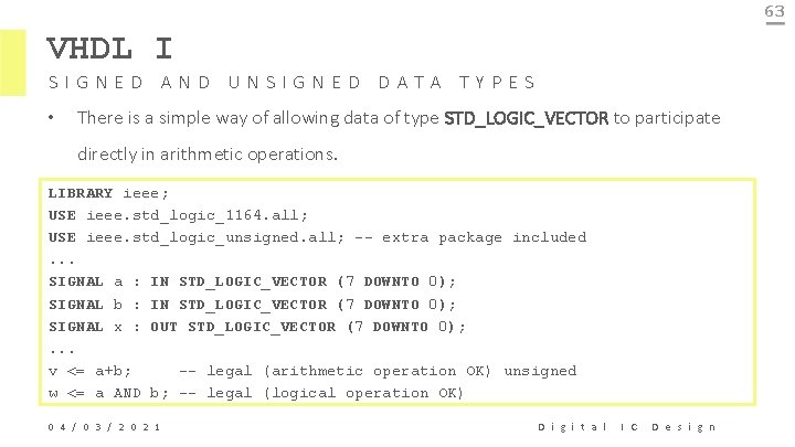
63 VHDL I SIGNED AND UNSIGNED DATA TYPES • There is a simple way of allowing data of type STD_LOGIC_VECTOR to participate directly in arithmetic operations. LIBRARY ieee; USE ieee. std_logic_1164. all; USE ieee. std_logic_unsigned. all; -- extra package included. . . SIGNAL a : IN STD_LOGIC_VECTOR (7 DOWNTO 0); SIGNAL b : IN STD_LOGIC_VECTOR (7 DOWNTO 0); SIGNAL x : OUT STD_LOGIC_VECTOR (7 DOWNTO 0); . . . v <= a+b; -- legal (arithmetic operation OK) unsigned w <= a AND b; -- legal (logical operation OK) 0 4 / 0 3 / 2 0 2 1 D i g i t a l I C D e s i g n
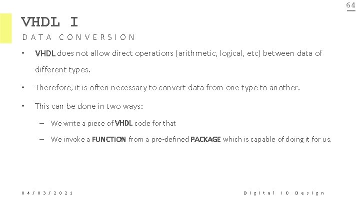
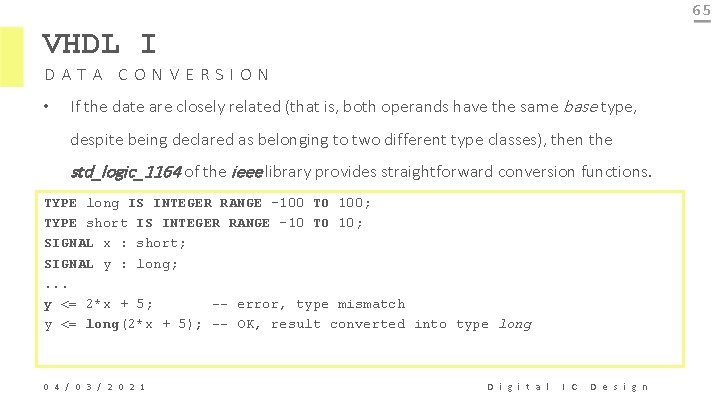
64 VHDL I DATA CONVERSION • VHDL does not allow direct operations (arithmetic, logical, etc) between data of different types. • Therefore, it is often necessary to convert data from one type to another. • This can be done in two ways: – We write a piece of VHDL code for that – We invoke a FUNCTION from a pre-defined PACKAGE which is capable of doing it for us. 0 4 / 0 3 / 2 0 2 1 D i g i t a l I C D e s i g n
65 VHDL I DATA CONVERSION • If the date are closely related (that is, both operands have the same base type, despite being declared as belonging to two different type classes), then the std_logic_1164 of the ieee library provides straightforward conversion functions. TYPE long IS INTEGER RANGE -100 TO 100; TYPE short IS INTEGER RANGE -10 TO 10; SIGNAL x : short; SIGNAL y : long; . . . y <= 2*x + 5; -- error, type mismatch y <= long(2*x + 5); -- OK, result converted into type long 0 4 / 0 3 / 2 0 2 1 D i g i t a l I C D e s i g n
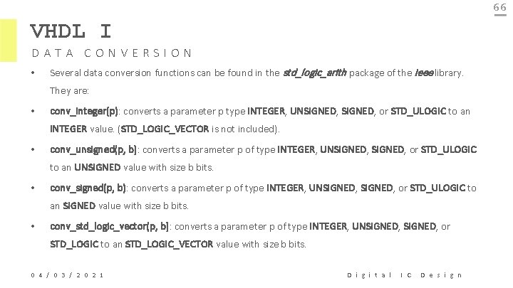
66 VHDL I DATA CONVERSION • Several data conversion functions can be found in the std_logic_arith package of the ieee library. They are: • conv_integer(p): converts a parameter p type INTEGER, UNSIGNED, or STD_ULOGIC to an INTEGER value. (STD_LOGIC_VECTOR is not included). • conv_unsigned(p, b): converts a parameter p of type INTEGER, UNSIGNED, or STD_ULOGIC to an UNSIGNED value with size b bits. • conv_signed(p, b): converts a parameter p of type INTEGER, UNSIGNED, or STD_ULOGIC to an SIGNED value with size b bits. • conv_std_logic_vector(p, b): converts a parameter p of type INTEGER, UNSIGNED, or STD_LOGIC to an STD_LOGIC_VECTOR value with size b bits. 0 4 / 0 3 / 2 0 2 1 D i g i t a l I C D e s i g n
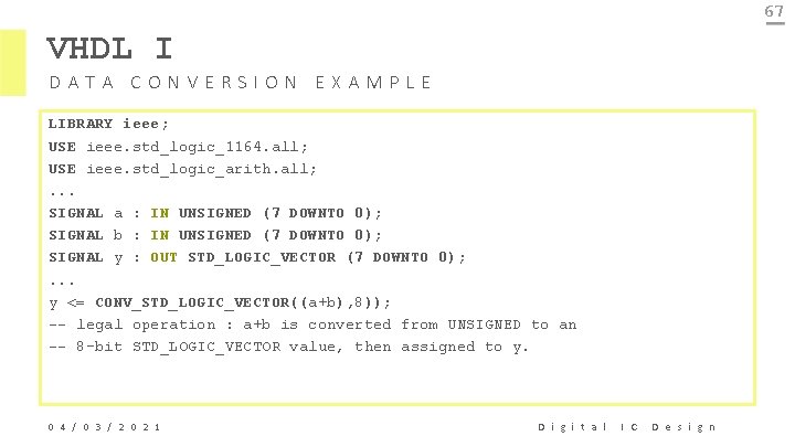
67 VHDL I DATA CONVERSION EXAMPLE LIBRARY ieee; USE ieee. std_logic_1164. all; USE ieee. std_logic_arith. all; . . . SIGNAL a : IN UNSIGNED (7 DOWNTO 0); SIGNAL b : IN UNSIGNED (7 DOWNTO 0); SIGNAL y : OUT STD_LOGIC_VECTOR (7 DOWNTO 0); . . . y <= CONV_STD_LOGIC_VECTOR((a+b), 8)); -- legal operation : a+b is converted from UNSIGNED to an -- 8 -bit STD_LOGIC_VECTOR value, then assigned to y. 0 4 / 0 3 / 2 0 2 1 D i g i t a l I C D e s i g n
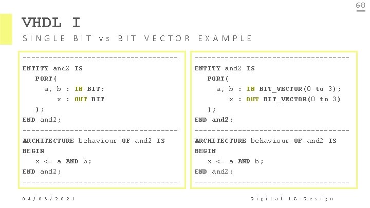
68 VHDL I SINGLE BIT vs BIT VECTOR EXAMPLE ------------------ENTITY and 2 IS PORT( a, b : IN BIT; x : OUT BIT ); END and 2; ------------------ARCHITECTURE behaviour OF and 2 IS BEGIN x <= a AND b; END and 2; ------------------0 4 / 0 3 / 2 0 2 1 ------------------ENTITY and 2 IS PORT( a, b : IN BIT_VECTOR(0 to 3); x : OUT BIT_VECTOR(0 to 3) ); END and 2; ------------------ARCHITECTURE behaviour OF and 2 IS BEGIN x <= a AND b; END and 2; ------------------D i g i t a l I C D e s i g n
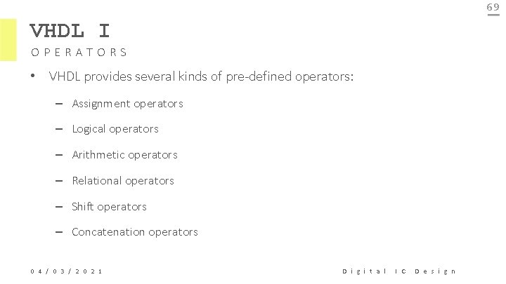
69 VHDL I OPERATORS • VHDL provides several kinds of pre-defined operators: – Assignment operators – Logical operators – Arithmetic operators – Relational operators – Shift operators – Concatenation operators 0 4 / 0 3 / 2 0 2 1 D i g i t a l I C D e s i g n
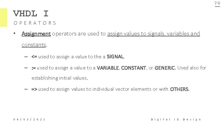
70 VHDL I OPERATORS • Assignment operators are used to assign values to signals, variables and constants. – <= used to assign a value to the a SIGNAL. – : = used to assign a value to a VARIABLE, CONSTANT, or GENERIC. Used also for establishing initial values. – => used to assign values to individual vector elements or with OTHERS. 0 4 / 0 3 / 2 0 2 1 D i g i t a l I C D e s i g n
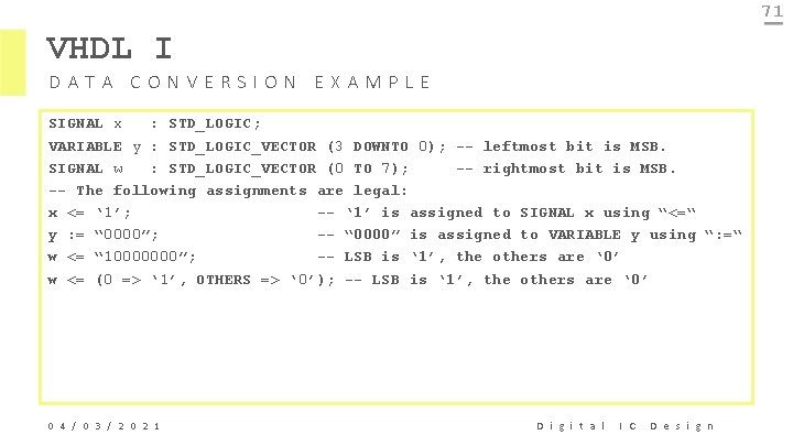
71 VHDL I DATA CONVERSION EXAMPLE SIGNAL x : STD_LOGIC; VARIABLE y : STD_LOGIC_VECTOR (3 DOWNTO 0); -- leftmost bit is MSB. SIGNAL w : STD_LOGIC_VECTOR (0 TO 7); -- rightmost bit is MSB. -- The following assignments are legal: x <= ‘ 1’; -- ‘ 1’ is assigned to SIGNAL x using “<=“ y : = “ 0000”; -- “ 0000” is assigned to VARIABLE y using “: =“ w <= “ 10000000”; -- LSB is ‘ 1’, the others are ‘ 0’ w <= (0 => ‘ 1’, OTHERS => ‘ 0’); -- LSB is ‘ 1’, the others are ‘ 0’ 0 4 / 0 3 / 2 0 2 1 D i g i t a l I C D e s i g n
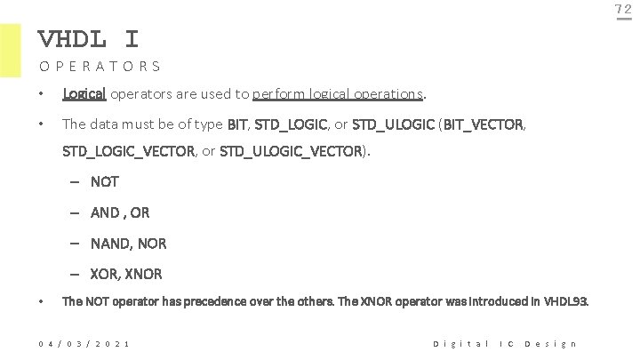
72 VHDL I OPERATORS • Logical operators are used to perform logical operations. • The data must be of type BIT, STD_LOGIC, or STD_ULOGIC (BIT_VECTOR, STD_LOGIC_VECTOR, or STD_ULOGIC_VECTOR). – NOT – AND , OR – NAND, NOR – XOR, XNOR • The NOT operator has precedence over the others. The XNOR operator was introduced in VHDL 93. 0 4 / 0 3 / 2 0 2 1 D i g i t a l I C D e s i g n
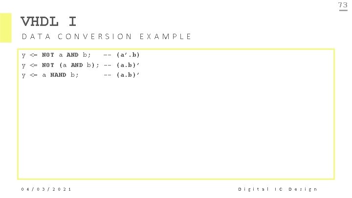
73 VHDL I DATA CONVERSION EXAMPLE y <= NOT a AND b; –- (a’. b) y <= NOT (a AND b); -- (a. b)’ y <= a NAND b; -- (a. b)’ 0 4 / 0 3 / 2 0 2 1 D i g i t a l I C D e s i g n
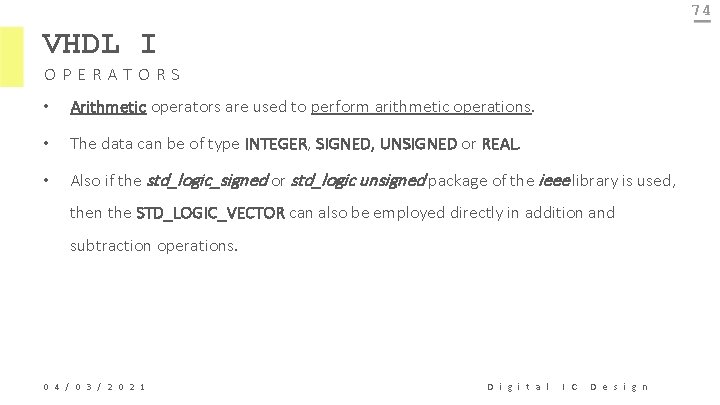
74 VHDL I OPERATORS • Arithmetic operators are used to perform arithmetic operations. • The data can be of type INTEGER, SIGNED, UNSIGNED or REAL. • Also if the std_logic_signed or std_logic unsigned package of the ieee library is used, then the STD_LOGIC_VECTOR can also be employed directly in addition and subtraction operations. 0 4 / 0 3 / 2 0 2 1 D i g i t a l I C D e s i g n
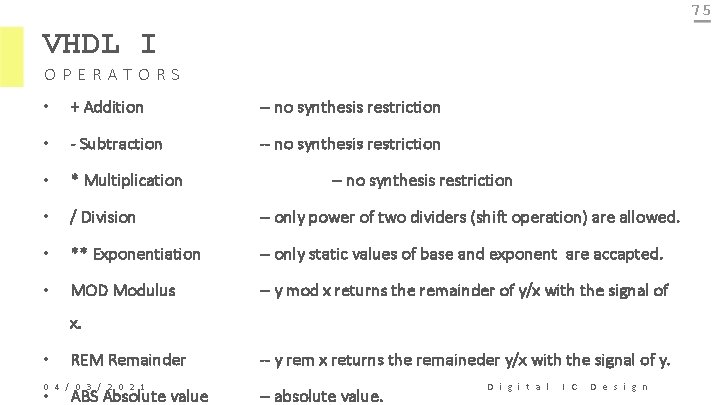
75 VHDL I OPERATORS • + Addition -- no synthesis restriction • - Subtraction -- no synthesis restriction • * Multiplication • / Division -- only power of two dividers (shift operation) are allowed. • ** Exponentiation -- only static values of base and exponent are accapted. • MOD Modulus -- y mod x returns the remainder of y/x with the signal of -- no synthesis restriction x. • REM Remainder 0 4 / 0 3 / 2 0 2 1 • ABS Absolute value -- y rem x returns the remaineder y/x with the signal of y. -- absolute value. D i g i t a l I C D e s i g n
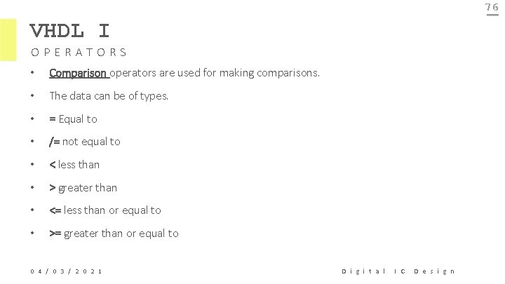
76 VHDL I OPERATORS • Comparison operators are used for making comparisons. • The data can be of types. • = Equal to • /= not equal to • < less than • > greater than • <= less than or equal to • >= greater than or equal to 0 4 / 0 3 / 2 0 2 1 D i g i t a l I C D e s i g n
77 VHDL I OPERATORS • Shift operators are used for shifting data. They were introduced in VHDL 93. • Their syntax is the following: <left operand> <shift operation> <right operand>. • The left operand must be of type BIT_VECTOR, while the right operand must be an INTEGER (+ or – in front of it is accepted). • sll shift left logic – positions on the right are filled with ‘ 0’s. • srl shift right logic – positions on the left are filled with ‘ 0’s 0 4 / 0 3 / 2 0 2 1 D i g i t a l I C D e s i g n
78 VHDL I DATA ATTRIBUTES • The pre-defined, synthesisable data attributes are the following: • d’LOW: returns lower array index • d’HIGH: returns upper array index • d’LEFT: returns leftmost array index • d’RIGHT: returns rightmost array index • d’LENGTH: returns vector size • d’RANGE: returns vector range • d’REVERSE_RANGE: returns vector range in reverse order 0 4 / 0 3 / 2 0 2 1 D i g i t a l I C D e s i g n
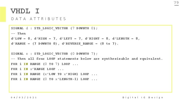
79 VHDL I DATA ATTRIBUTES SIGNAL d : STD_LOGIC_VECTOR (7 DOWNTO 0); -- Then d’LOW = 0, d’HIGH = 7, d’LEFT = 7, d’RIGHT = 0, d’LENGTH = 8, d’RANGE = (7 DOWNTO 0), d’REVERSE_RANGE = (0 to 7). SIGNAL x : STD_LOGIC_VECTOR (0 DOWNTO 7); -- Then all four LOOP statements below are synthesisable and equivalent. FOR i IN RANGE (0 TO 7) LOOP. . . FOR i IN x’RANGE LOOP. . . FOR i IN RANGE (x’LOW TO x’HIGH) LOOP. . . FOR i IN RANGE (0 TO x’LENGTH-1) LOOP. . . 0 4 / 0 3 / 2 0 2 1 D i g i t a l I C D e s i g n
80 VHDL I DATA ATTRIBUTES • If the signals is of enumerated type, then: • d’VAL (pos): returns value in the position specified. • d’POS(value): returns position of the value specified. • d’LEFTOF(value): returns value in the position to the left of the value specified. 0 4 / 0 3 / 2 0 2 1 D i g i t a l I C D e s i g n
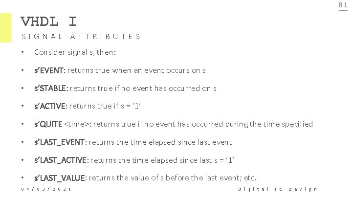
81 VHDL I SIGNAL ATTRIBUTES • Consider signal s, then: • s’EVENT: returns true when an event occurs on s • s’STABLE: returns true if no event has occurred on s • s’ACTIVE: returns true if s = ‘ 1’ • s’QUITE <time>: returns true if no event has occurred during the time specified • s’LAST_EVENT: returns the time elapsed since last event • s’LAST_ACTIVE: returns the time elapsed since last s = ‘ 1’ • s’LAST_VALUE: returns the value of s before the last event; etc. 0 4 / 0 3 / 2 0 2 1 D i g i t a l I C D e s i g n
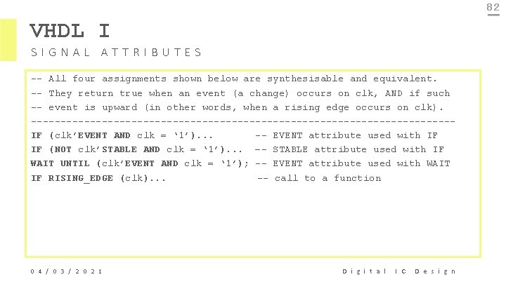
82 VHDL I SIGNAL ATTRIBUTES -- All four assignments shown below are synthesisable and equivalent. -- They return true when an event (a change) occurs on clk, AND if such -- event is upward (in other words, when a rising edge occurs on clk). ------------------------------------IF (clk’EVENT AND clk = ‘ 1’). . . -- EVENT attribute used with IF IF (NOT clk’STABLE AND clk = ‘ 1’). . . –- STABLE attribute used with IF WAIT UNTIL (clk’EVENT AND clk = ‘ 1’); -- EVENT attribute used with WAIT IF RISING_EDGE (clk). . . -- call to a function 0 4 / 0 3 / 2 0 2 1 D i g i t a l I C D e s i g n
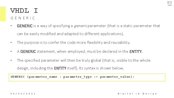
83 VHDL I GENERIC • GENERIC is a way of specifying a generic parameter (that is a static parameter that can be easily modified and adapted to different applications). • The purpose is to confer the code more flexibility and reusability. • A GENERIC statement, when employed, must be declared in the ENTITY. • The specified parameter will then be truly global (that is, visible to the whole design, including the ENTITY itself). Its syntax is shown below. GENERIC (parameter_name : parameter_type : = parameter_value); 0 4 / 0 3 / 2 0 2 1 D i g i t a l I C D e s i g n
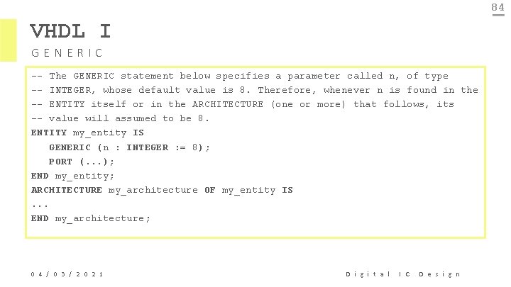
84 VHDL I GENERIC -- The GENERIC statement below specifies a parameter called n, of type -- INTEGER, whose default value is 8. Therefore, whenever n is found in the -- ENTITY itself or in the ARCHITECTURE (one or more) that follows, its -- value will assumed to be 8. ENTITY my_entity IS GENERIC (n : INTEGER : = 8); PORT (. . . ); END my_entity; ARCHITECTURE my_architecture OF my_entity IS. . . END my_architecture; 0 4 / 0 3 / 2 0 2 1 D i g i t a l I C D e s i g n
85 THANK YOU! Any Question? 0 4 / 0 3 / 2 0 2 1 D i g i t a l I C D e s i g n