
EECS 498 Advanced Embedded Systems Lecture 8 Topic
EECS 498 Advanced Embedded Systems Lecture 8: Topic Groups, RTOS Review & Power Introduction
Today… Today we are covering three things • Topic group stuff (5 minutes) • Start on electrical issues for PCBs – Specifically power integrity issues • And necessarily some review on power/energy topics • RTOS review (10 -15 minutes? )
First: Candy bars I owe?
Topic groups and dates • 10/31: TBD topic, Touch panels • 11/7: OBD, USB • 11/14: Audio Jack, Cameras
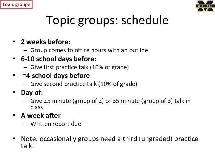
Topic groups: schedule • 2 weeks before: – Group comes to office hours with an outline. • 6 -10 school days before: – Give first practice talk (10% of grade) • ~4 school days before – Give second practice talk (10% of grade) • Day of: – Give 25 minute (group of 2) or 35 minute (group of 3) talk in class. • A week after – Written report due • Note: occasionally groups need a third (ungraded) practice talk.
Topic groups Doodle for practice talks • First set of appointment times: – http: //tinyurl. com/498 f 12 -talks 1
Some electrical issues related to the building of PCBs
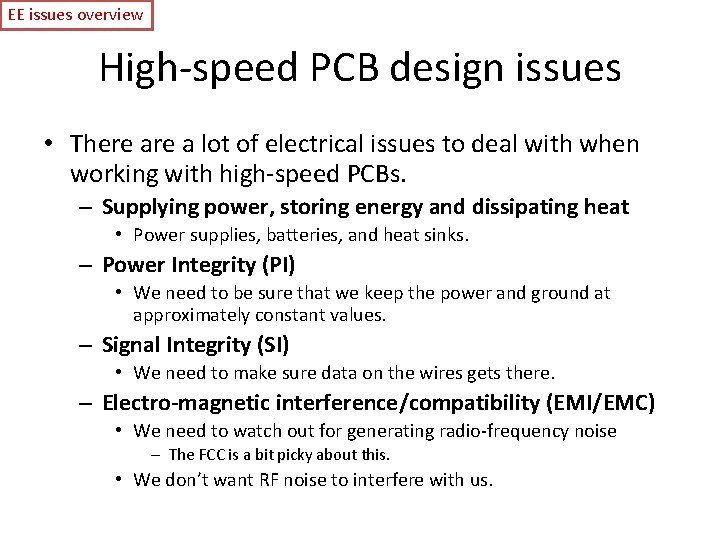
EE issues overview High-speed PCB design issues • There a lot of electrical issues to deal with when working with high-speed PCBs. – Supplying power, storing energy and dissipating heat • Power supplies, batteries, and heat sinks. – Power Integrity (PI) • We need to be sure that we keep the power and ground at approximately constant values. – Signal Integrity (SI) • We need to make sure data on the wires gets there. – Electro-magnetic interference/compatibility (EMI/EMC) • We need to watch out for generating radio-frequency noise – The FCC is a bit picky about this. • We don’t want RF noise to interfere with us.
Outline • Background – Understanding power and energy – Basics of In • EECS 215 “review/introduction” – On capacitors, inductors, resistors and impedance • Power integrity (PI)
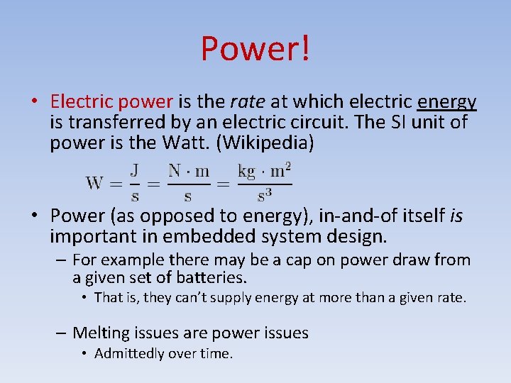
Power! • Electric power is the rate at which electric energy is transferred by an electric circuit. The SI unit of power is the Watt. (Wikipedia) • Power (as opposed to energy), in-and-of itself is important in embedded system design. – For example there may be a cap on power draw from a given set of batteries. • That is, they can’t supply energy at more than a given rate. – Melting issues are power issues • Admittedly over time.
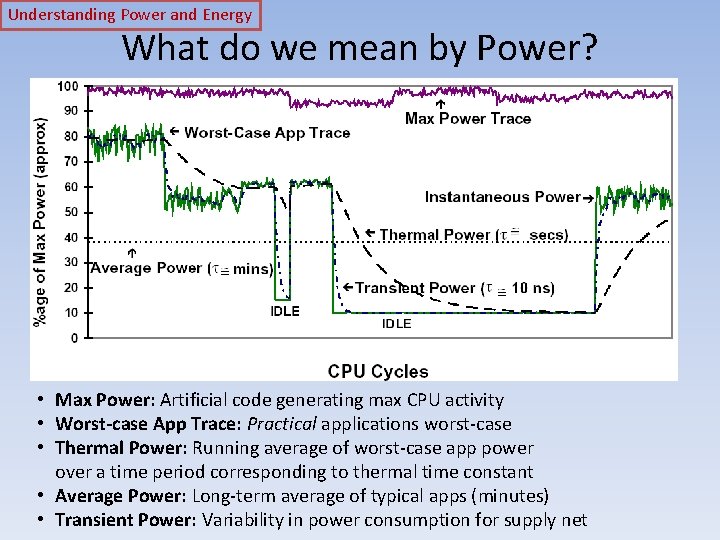
Understanding Power and Energy What do we mean by Power? • Max Power: Artificial code generating max CPU activity • Worst-case App Trace: Practical applications worst-case • Thermal Power: Running average of worst-case app power over a time period corresponding to thermal time constant • Average Power: Long-term average of typical apps (minutes) • Transient Power: Variability in power consumption for supply net
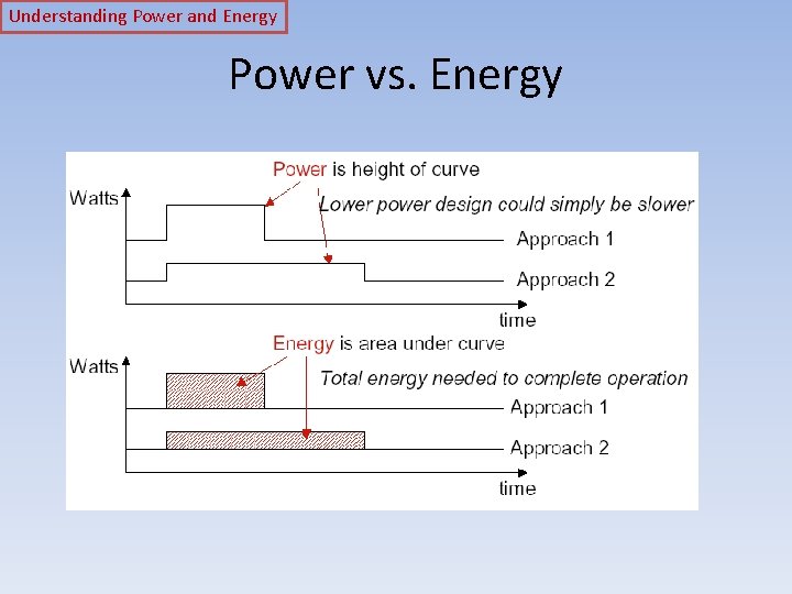
Understanding Power and Energy Power vs. Energy • Power consumption in Watts – Determines battery life in hours – Sets packaging limits • Energy efficiency in Joules – Rate at which power is consumed over time – Energy = power * delay (Joules = Watts * seconds) – Lower energy number means less power to perform a computation at same frequency
Understanding Power and Energy Power vs. Energy
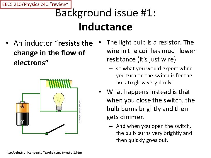
EECS 215/Physics 240 “review” Background issue #1: Inductance • An inductor “resists the • The light bulb is a resistor. The wire in the coil has much lower change in the flow of resistance (it's just wire) electrons” – so what you would expect when you turn on the switch is for the bulb to glow very dimly. • What happens instead is that when you close the switch, the bulb burns brightly and then gets dimmer. – And when you open the switch, the bulb burns very brightly and then quickly goes out. http: //electronics. howstuffworks. com/inductor 1. htm
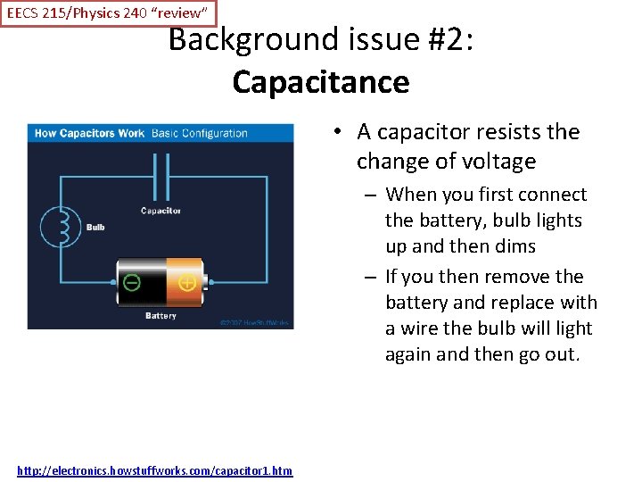
EECS 215/Physics 240 “review” Background issue #2: Capacitance • A capacitor resists the change of voltage – When you first connect the battery, bulb lights up and then dims – If you then remove the battery and replace with a wire the bulb will light again and then go out. http: //electronics. howstuffworks. com/capacitor 1. htm
EECS 215/Physics 240 “review” Background issue #3: Impendence • Impedance (symbol Z) is a measure of the overall opposition of a circuit to current, in other words: how much the circuit impedes the flow of current. – It is like resistance, but it also takes into account the effects of capacitance and inductance. I – Impedance is measured in ohms. – Impedance is more complex than resistance because the effects of capacitance and inductance vary with the frequency of the current passing through the circuit and this means impedance varies with frequency! • The effect of resistance is constant regardless of frequency. http: //www. kpsec. freeuk. com/imped. htm
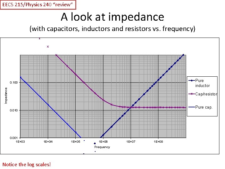
EECS 215/Physics 240 “review” A look at impedance (with capacitors, inductors and resistors vs. frequency) Pure inductor Impedance 0. 100 Cap/resistor Pure cap. 0. 010 0. 001 1 E+03 1 E+04 1 E+05 1 E+06 Frequency Notice the log scales! 1 E+07 1 E+08
Power Integrity • In order to get digital electronics to work correctly, they need a minimum voltage differential. – If we get below that, the devices might • • Be slow (and thus not meet setup times) Lose state Reset or halt Just plain not work. • Even a very (very) short “power droop” can cause the chip to die. – In my experience, this is a really common problem. • Keeping power/ground constant and noise/droop free is “Power Integrity”
Power Integrity So? • We need the • We basically want a “no Vcc/Ground differential -pass” filter. to be fairly constant. – That is we don’t want to – But rapid changes in the amount of current needed will cause the voltage to spike or droop due to inductance. see any signal on the Vcc/Ground lines. – The obvious thing? • “Add a capacitor” – That should keep the voltage constant, right? • The problem is we need to worry about a lot of frequencies AND capacitors aren’t ideal.
Power Integrity Lots of frequencies • Even fairly slow devices • This means we generally these days are capable have to worry about of switching at very high frequencies from DC all frequencies. the way to 1 GHz. – Basically we get drivers that have rise and fall times capable of going 1 GHz or so. – Because our chip may be varying its draw at rates up to that fast.
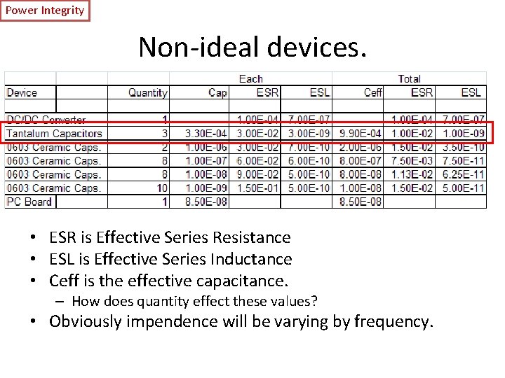
Power Integrity Non-ideal devices. • ESR is Effective Series Resistance • ESL is Effective Series Inductance • Ceff is the effective capacitance. – How does quantity effect these values? • Obviously impendence will be varying by frequency.
Power Integrity Other things can add to ESR/ESL • Generally a bad solder job can make ESR/ESL worse. • Packaging has an impact – wires have inductance so surface-mount packages preferred • Pads can have an impact
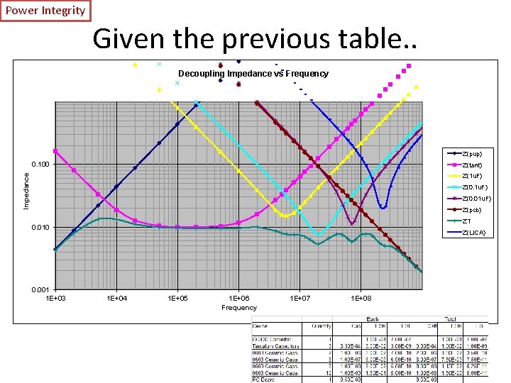
Power Integrity Given the previous table. . Decoupling Impedance vs Frequency Z(pup) 0. 100 Z(tant) Impedance Z(1 u. F) Z(0. 01 u. F) Z(pcb) ZT 0. 010 0. 001 1 E+03 Z(LICA) 1 E+04 1 E+05 1 E+06 Frequency 1 E+07 1 E+08
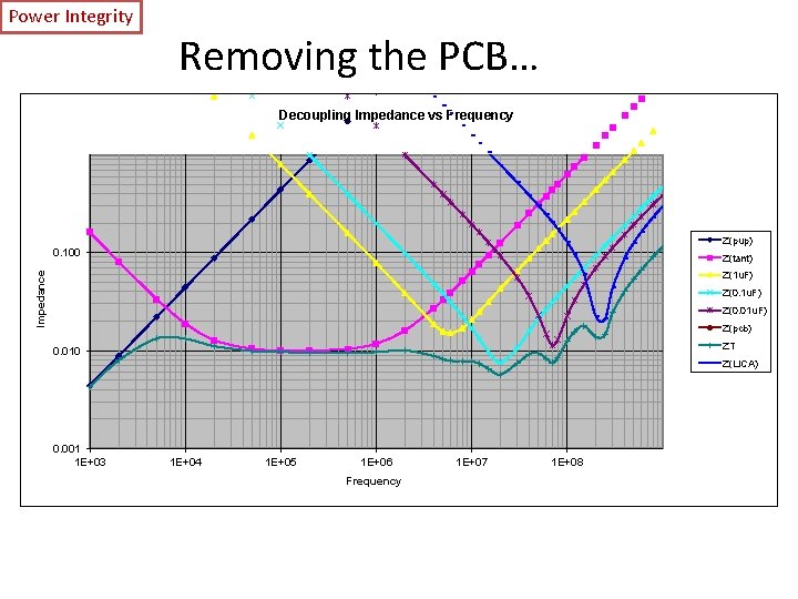
Power Integrity Removing the PCB… Decoupling Impedance vs Frequency Z(pup) 0. 100 Z(tant) Impedance Z(1 u. F) Z(0. 01 u. F) Z(pcb) ZT 0. 010 Z(LICA) 0. 001 1 E+03 1 E+04 1 E+05 1 E+06 Frequency 1 E+07 1 E+08
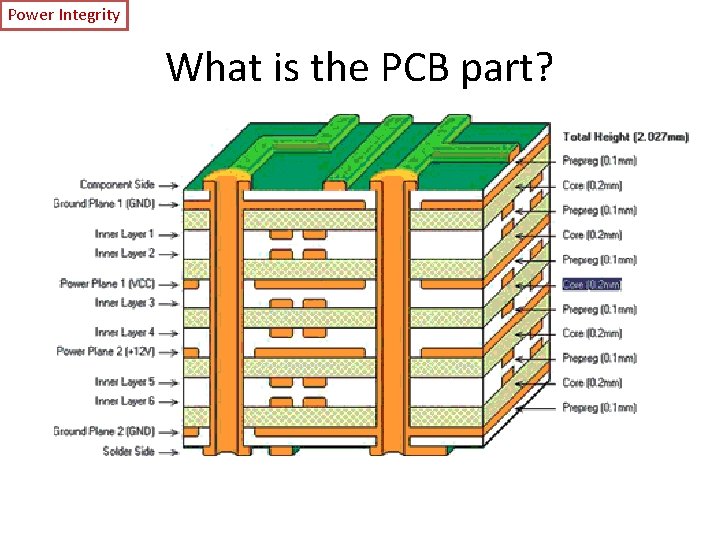
Power Integrity What is the PCB part?
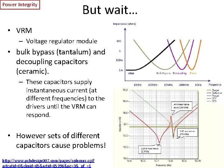
Power Integrity But wait… • VRM – Voltage regulator module • bulk bypass (tantalum) and decoupling capacitors (ceramic). – These capacitors supply instantaneous current (at different frequencies) to the drivers until the VRM can respond. • However sets of different capacitors cause problems! http: //www. pcbdesign 007. com/pages/columns. cgi? artcatid=0&clmid=65&artid=85396&pg=3&_pf_=1
Power Integrity (PI) summary • Power integrity is about keeping the Vcc/ground difference constant. – This is hard because the devices that sink power do so in “pulses” due to their own clocks – Need caps to keep value constant • But parasitic ESR/ESL cause problems • So lots of them==good – Reduce ESR/ESL – Increase capacitance. – But anti-resonance can cause problems! • Need Spice or other tools to model.
RTOS review/context • Going to discuss ticks, scheduler and more. – Done on board.
- Slides: 28