
EECS 373 Design of MicroprocessorBased Systems Branden Ghena
EECS 373 Design of Microprocessor-Based Systems Branden Ghena University of Michigan Lecture 4: Memory-Mapped I/O, Bus Architectures September 11, 2014 Slides developed in part by Mark Brehob & Prabal Dutta 1
Today… Memory-Mapped I/O Example Bus with Memory-Mapped I/O Bus Architectures AMBA APB 2
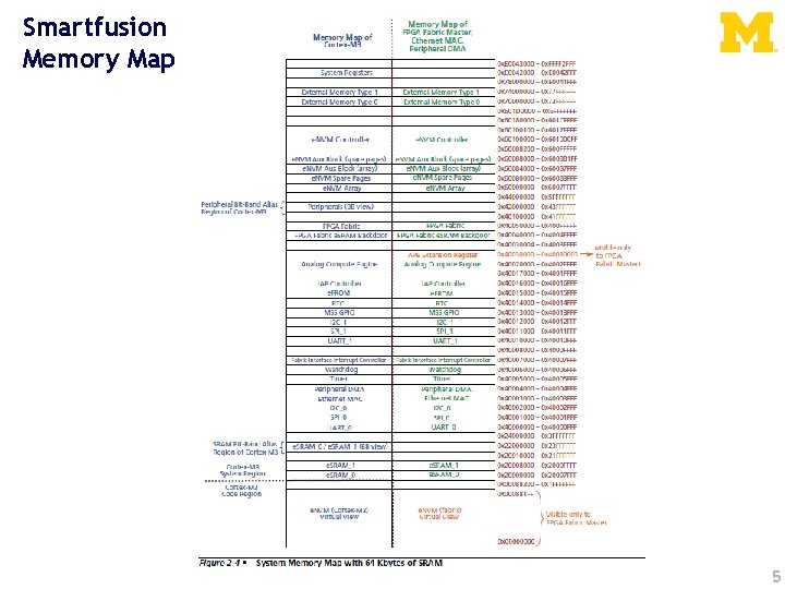
Memory-mapped I/O • Microcontrollers have many interesting peripherals – But how do you interact with them? • Need to: – Send commands – Configure device – Receive data • But we don’t want new processor instructions for everything – Actually, it would be great if the processor know anything weird was going on at all 3
Memory-mapped I/O • Instead of real memory, some addresses map to I/O devices instead Example: • Address 0 x 80000004 is a General Purpose I/O (GPIO) Pin – Writing a 1 to that address would turn it on – Writing a 0 to that address would turn it off – Reading at that address would return the value (1 or 0) 4
Smartfusion Memory Map 5
Memory-mapped I/O • Instead of real memory, some addresses map to I/O devices instead • But how do you make this happen? – MAGIC isn’t a bad guess, but not very helpful Let’s start by looking at how a memory bus works 6
Today… Memory-Mapped I/O Example Bus with Memory-Mapped I/O Bus Architectures AMBA APB 7
Bus terminology • Any given transaction have an “initiator” and “target” • Any device capable of being an initiator is said to be a “bus master” – In many cases there is only one bus master (single master vs. multi-master). • A device that can only be a target is said to be a slave device. 8
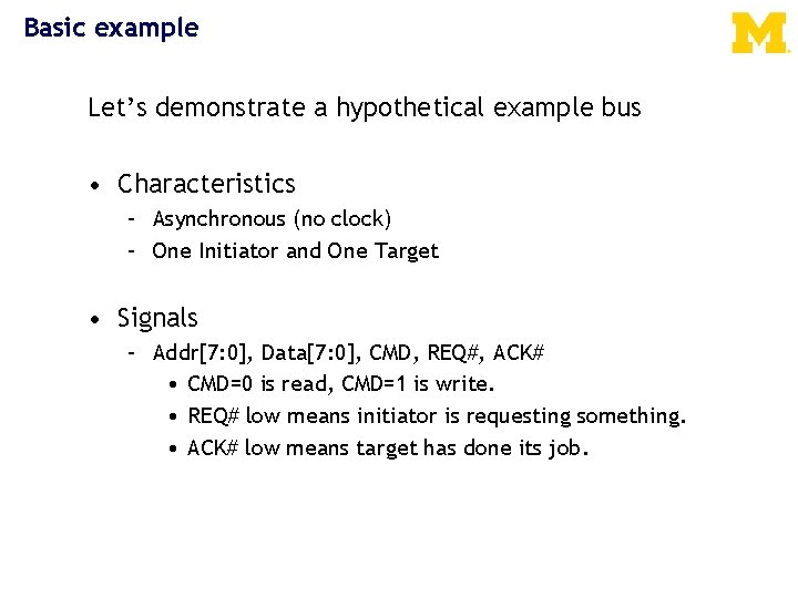
Basic example Let’s demonstrate a hypothetical example bus • Characteristics – Asynchronous (no clock) – One Initiator and One Target • Signals – Addr[7: 0], Data[7: 0], CMD, REQ#, ACK# • CMD=0 is read, CMD=1 is write. • REQ# low means initiator is requesting something. • ACK# low means target has done its job.

Read transaction Initiator wants to read location 0 x 24 A BC D Addr[7: 0] ? ? E F 0 x 24 G HI ? ? CMD Data[7: 0] ? ? 0 x 55 ? ? REQ# ACK# G: Transaction H: I: Target sets is ACK# complete, to high, Bus Stops isitidle driving data and A: E: Target Addr to =Eto 0 x 24, low CMD =F 0 Addr D: F: Initiator drives sees data and latches B: Initiator sets REQ# low C: sees read A BACK# C Drequest G H I CMD
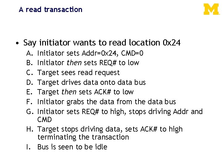
A read transaction • Say initiator wants to read location 0 x 24 A. B. C. D. E. F. G. Initiator sets Addr=0 x 24, CMD=0 Initiator then sets REQ# to low Target sees read request Target drives data onto data bus Target then sets ACK# to low Initiator grabs the data from the data bus Initiator sets REQ# to high, stops driving Addr and CMD H. Target stops driving data, sets ACK# to high terminating the transaction I. Bus is seen to be idle
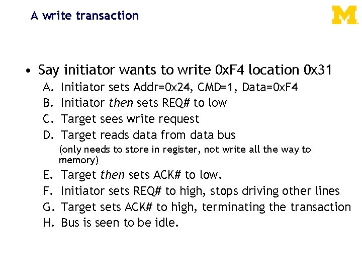
A write transaction • Say initiator wants to write 0 x. F 4 location 0 x 31 A. B. C. D. Initiator sets Addr=0 x 24, CMD=1, Data=0 x. F 4 Initiator then sets REQ# to low Target sees write request Target reads data from data bus (only needs to store in register, not write all the way to memory) E. F. G. H. Target then sets ACK# to low. Initiator sets REQ# to high, stops driving other lines Target sets ACK# to high, terminating the transaction Bus is seen to be idle.
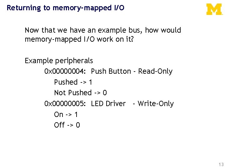
Returning to memory-mapped I/O Now that we have an example bus, how would memory-mapped I/O work on it? Example peripherals 0 x 00000004: Push Button - Read-Only Pushed -> 1 Not Pushed -> 0 0 x 00000005: LED Driver - Write-Only On -> 1 Off -> 0 13
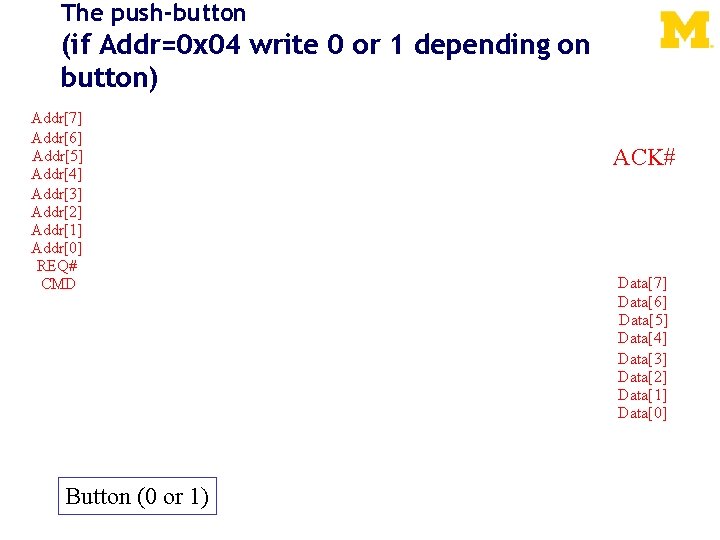
The push-button (if Addr=0 x 04 write 0 or 1 depending on button) Addr[7] Addr[6] Addr[5] Addr[4] Addr[3] Addr[2] Addr[1] Addr[0] REQ# CMD Button (0 or 1) ACK# Data[7] Data[6] Data[5] Data[4] Data[3] Data[2] Data[1] Data[0]
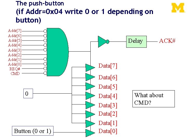
The push-button (if Addr=0 x 04 write 0 or 1 depending on button) Addr[7] Addr[6] Addr[5] Addr[4] Addr[3] Addr[2] Addr[1] Addr[0] REQ# CMD Delay ACK# Data[7] 0 Button (0 or 1) Data[6] Data[5] Data[4] Data[3] Data[2] Data[1] Data[0] What about CMD?

The LED (1 bit reg written by LSB of address 0 x 05) Addr[7] Addr[6] Addr[5] Addr[4] Addr[3] Addr[2] Addr[1] Addr[0] REQ# CMD DATA[7] DATA[6] DATA[5] DATA[4] DATA[3] DATA[2] DATA[1] DATA[0] ACK# LED
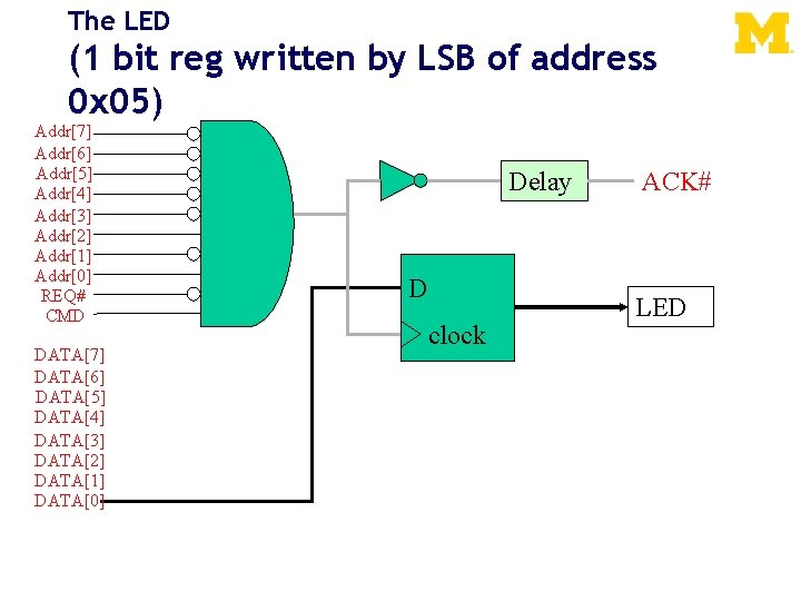
The LED (1 bit reg written by LSB of address 0 x 05) Addr[7] Addr[6] Addr[5] Addr[4] Addr[3] Addr[2] Addr[1] Addr[0] REQ# CMD DATA[7] DATA[6] DATA[5] DATA[4] DATA[3] DATA[2] DATA[1] DATA[0] Delay D clock ACK# LED
Let’s write a simple assembly program Light on if button is pressed. Peripheral Details 0 x 00000004: Push Button - Read-Only Pushed -> 1 Not Pushed -> 0 0 x 00000005: LED Driver - Write-Only On -> 1 Off -> 0 18
Today… Memory-Mapped I/O Example Bus with Memory-Mapped I/O Bus Architectures AMBA APB 19

Driving shared wires • It is commonly the case that some shared wires might have more than one potential device that needs to drive them. – For example there might be a shared data bus that is used by the targets and the initiator. We saw this in the simple bus. – In that case, we need a way to allow one device to control the wires while the others “stay out of the way” • Most common solutions are: – using tri-state drivers (so only one device is driving the bus at a time) – using open-collector connections (so if any device drives a 0 there is a 0 on the bus otherwise there is a 1) 20
Or just say no to shared wires. • Another option is to not share wires that could be driven by more than one device. . . – This can be really expensive. • Each target device would need its own data bus. • That’s a LOT of wires! – Not doable when connecting chips on a PCB as you are paying for each pin. – Quite doable (though not pretty) inside of a chip. 21
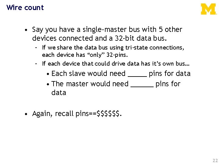
Wire count • Say you have a single-master bus with 5 other devices connected and a 32 -bit data bus. – If we share the data bus using tri-state connections, each device has “only” 32 -pins. – If each device that could drive data has it’s own bus… • Each slave would need _____ pins for data • The master would need ______ pins for data • Again, recall pins==$$$$$$. 22
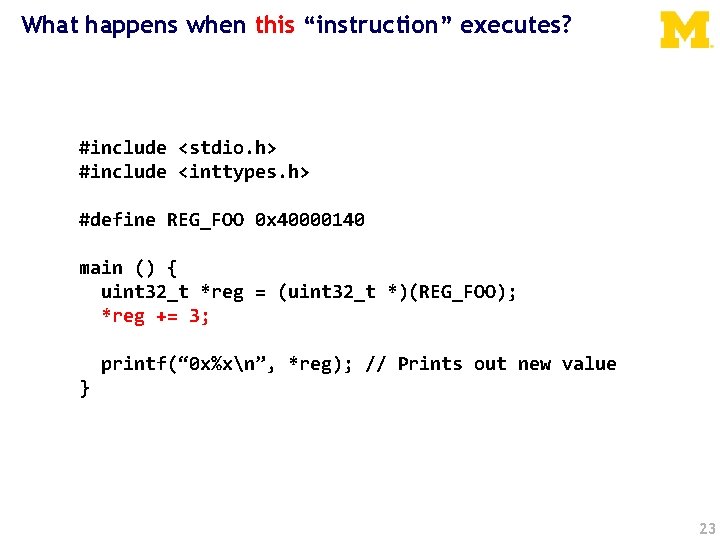
What happens when this “instruction” executes? #include <stdio. h> #include <inttypes. h> #define REG_FOO 0 x 40000140 main () { uint 32_t *reg = (uint 32_t *)(REG_FOO); *reg += 3; printf(“ 0 x%xn”, *reg); // Prints out new value } 23
“*reg += 3” is turned into a ld, add, str sequence • Load instruction – – – A bus read operation commences The CPU drives the address “reg” onto the address bus The CPU indicated a read operation is in process (e. g. R/W#) Some “handshaking” occurs The target drives the contents of “reg” onto the data lines The contents of “reg” is loaded into a CPU register (e. g. r 0) • Add instruction – An immediate add (e. g. add r 0, #3) adds three to this value • Store instruction – – – A bus write operation commences The CPU drives the address “reg” onto the address bus The CPU indicated a write operation is in process (e. g. R/W#) Some “handshaking” occurs The CPU drives the contents of “r 0” onto the data lines The target stores the data value into address “reg” 24
Details of the bus “handshaking” depend on the particular memory/peripherals involved • So. C memory/peripherals – AMBA AHB/APB • NAND Flash – Open NAND Flash Interface (ONFI) • DDR SDRAM – JEDEC JESD 79, JESD 79 -2 F, etc. 25
Why use a standardized bus? • Downsides – Have to follow the specification – Probably has actions that are unnecessary • Upside – Generic systems – Allows modules to be reused on different systems 26
Today… Memory-Mapped I/O Example Bus with Memory-Mapped I/O Bus Architectures AMBA APB 27
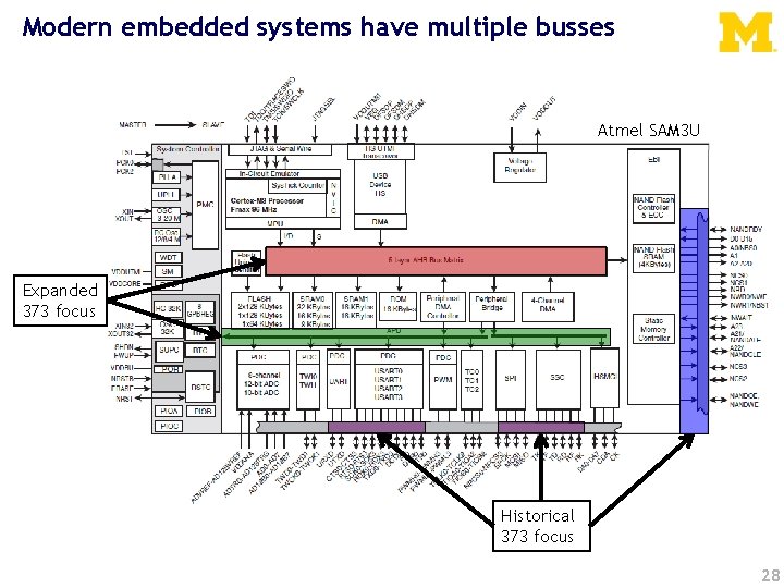
Modern embedded systems have multiple busses Atmel SAM 3 U Expanded 373 focus Historical 373 focus 28
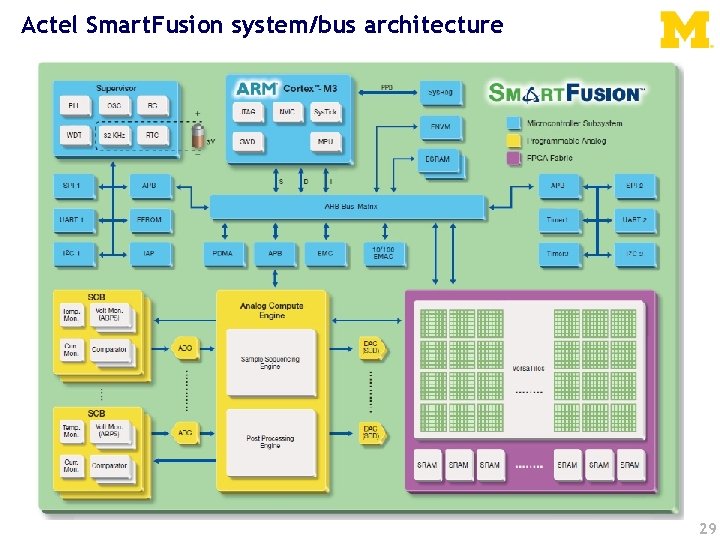
Actel Smart. Fusion system/bus architecture 29
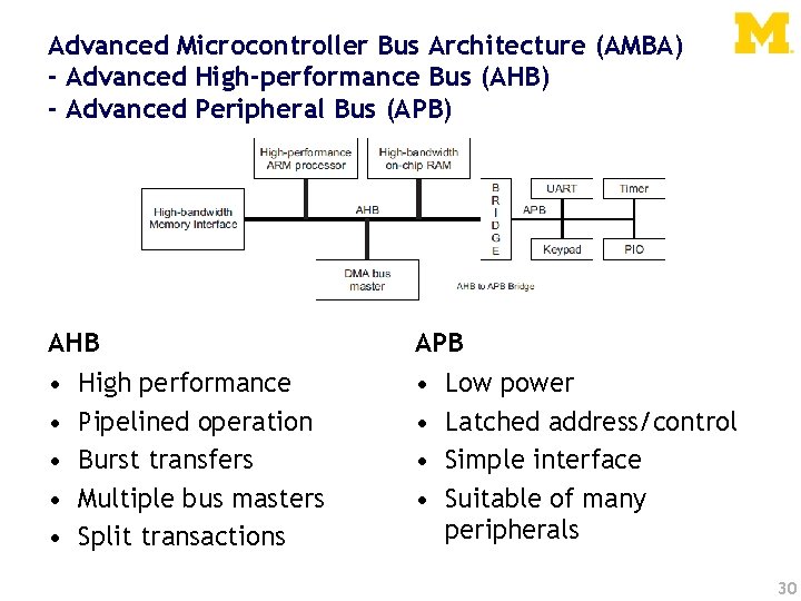
Advanced Microcontroller Bus Architecture (AMBA) - Advanced High-performance Bus (AHB) - Advanced Peripheral Bus (APB) AHB APB • • • High performance Pipelined operation Burst transfers Multiple bus masters Split transactions Low power Latched address/control Simple interface Suitable of many peripherals 30
APB is a fairly simple bus designed to be easy to work with. • Low-cost • Low-power • Low-complexity • Low-bandwidth • Non-pipelined • Ideal for peripherals 31

Notation 32
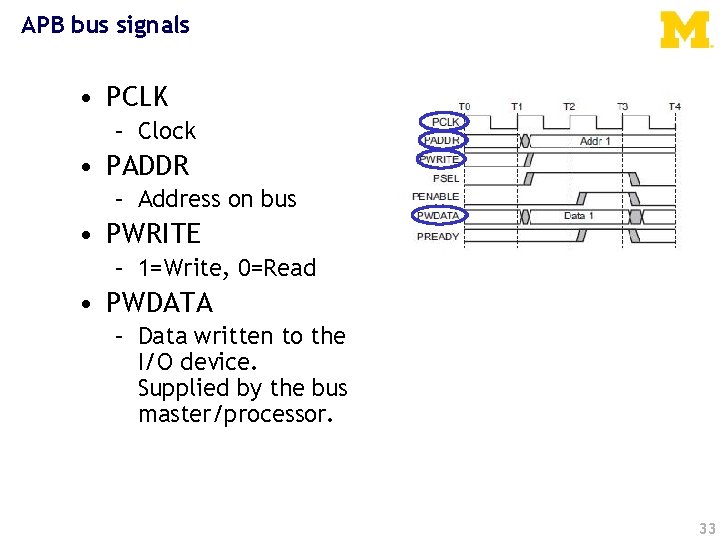
APB bus signals • PCLK – Clock • PADDR – Address on bus • PWRITE – 1=Write, 0=Read • PWDATA – Data written to the I/O device. Supplied by the bus master/processor. 33
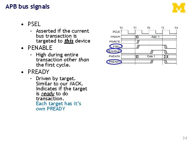
APB bus signals • PSEL – Asserted if the current bus transaction is targeted to this device • PENABLE – High during entire transaction other than the first cycle. • PREADY – Driven by target. Similar to our #ACK. Indicates if the target is ready to do transaction. Each target has it’s own PREADY 34
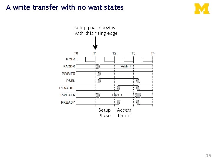
A write transfer with no wait states Setup phase begins with this rising edge Setup Phase Access Phase 35
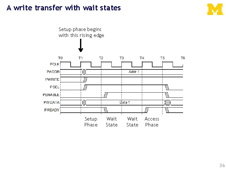
A write transfer with wait states Setup phase begins with this rising edge Setup Phase Wait State Access Phase 36
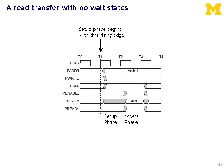
A read transfer with no wait states Setup phase begins with this rising edge Setup Phase Access Phase 37
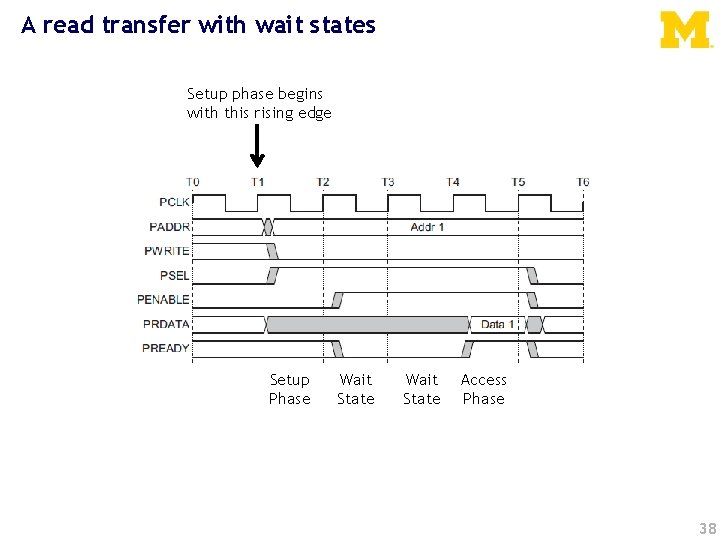
A read transfer with wait states Setup phase begins with this rising edge Setup Phase Wait State Access Phase 38
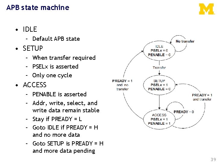
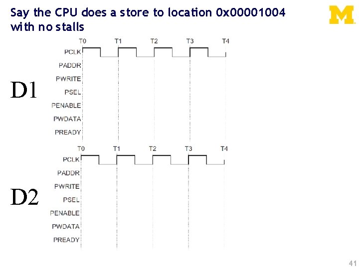
APB state machine • IDLE – Default APB state • SETUP – When transfer required – PSELx is asserted – Only one cycle • ACCESS – PENABLE is asserted – Addr, write, select, and write data remain stable – Stay if PREADY = L – Goto IDLE if PREADY = H and no more data – Goto SETUP is PREADY = H and more data pending 39
Example setup • For the next couple of slides, we will assume we have one bus master “CPU” and two slave devices (D 1 and D 2) – D 1 is mapped to 0 x 00001000 -0 x 0000100 F – D 2 is mapped to 0 x 00001010 -0 x 0000101 F
Say the CPU does a store to location 0 x 00001004 with no stalls D 1 D 2 41
Writes Let’s do some hardware examples! 42

Design device which register whenever What ifawe want to have writes the LSBtoofathis register control any address in its range is written an LED? PREADY PWDATA[31: 0] PWRITE PENABLE PSEL 32 -bit Reg D[31: 0] Q[31: 0] EN C LED PADDR[7: 0] PCLK We are assuming APB only gets lowest 8 bits of address here… 43
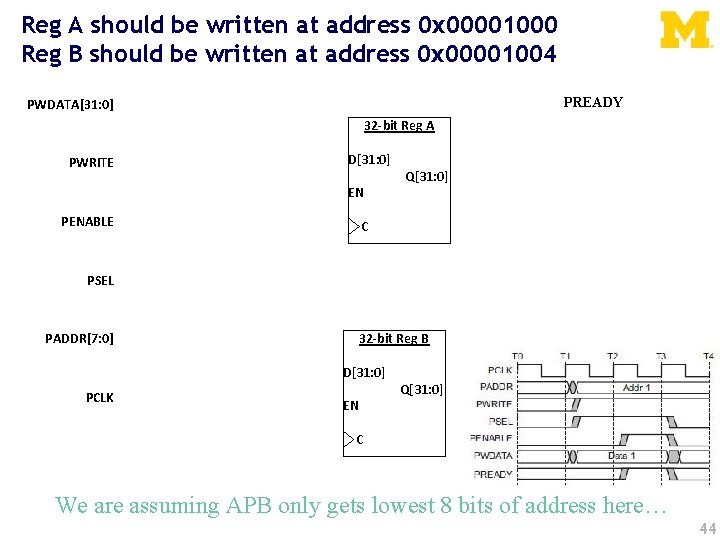
Reg A should be written at address 0 x 00001000 Reg B should be written at address 0 x 00001004 PREADY PWDATA[31: 0] PWRITE PENABLE 32 -bit Reg A D[31: 0] Q[31: 0] EN C PSEL PADDR[7: 0] PCLK 32 -bit Reg B D[31: 0] Q[31: 0] EN C We are assuming APB only gets lowest 8 bits of address here… 44
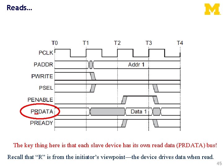
Reads… The key thing here is that each slave device has its own read data (PRDATA) bus! Recall that “R” is from the initiator’s viewpoint—the device drives data when read. 45

Let’s say we want a device that provides data from a switch on a read to any address it is assigned. (so returns a 0 or 1) PREADY PRDATA[32: 0] PWRITE PENABLE PSEL Mr. Switch PADDR[7: 0] PCLK 46
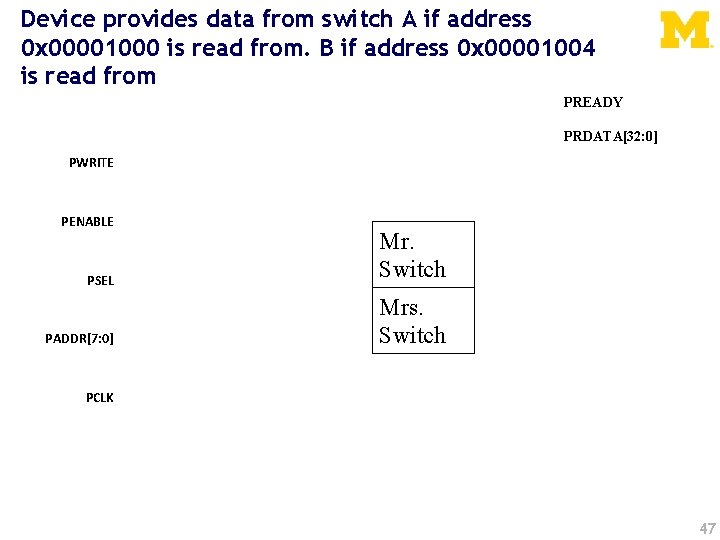
Device provides data from switch A if address 0 x 00001000 is read from. B if address 0 x 00001004 is read from PREADY PRDATA[32: 0] PWRITE PENABLE PSEL PADDR[7: 0] Mr. Switch Mrs. Switch PCLK 47
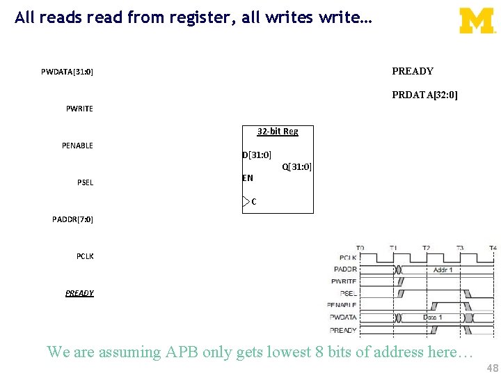
All reads read from register, all writes write… PREADY PWDATA[31: 0] PRDATA[32: 0] PWRITE PENABLE PSEL PADDR[7: 0] 32 -bit Reg D[31: 0] Q[31: 0] EN C PCLK PREADY We are assuming APB only gets lowest 8 bits of address here… 48
Things left out… • There is another signal, PSLVERR (APB Slave Error) which we can drive high if things go bad. – We’ll just tie that to 0. • PRESETn – Active low system reset signal – (needed for stateful peripherals) • Note that we are assuming that our device need not stall. – We could stall if needed. • I can’t find a limit on how long, but I suspect at some point the processor would generate an error. 49
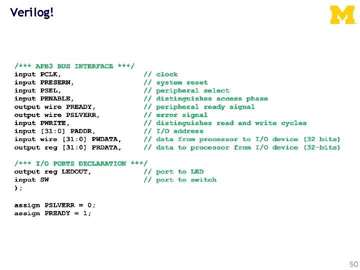
Verilog! 50
Questions? Comments? Discussion? 51
- Slides: 51