
EECS 150 Components and Design Techniques for Digital

- Slides: 41
EECS 150 - Components and Design Techniques for Digital Systems Lec 09 – Counters 9 -28 -04 David Culler Electrical Engineering and Computer Sciences University of California, Berkeley http: //www. eecs. berkeley. edu/~culler http: //www-inst. eecs. berkeley. edu/~cs 150 9/28/04 EECS 150 Fa 04 Lec 9 Counters
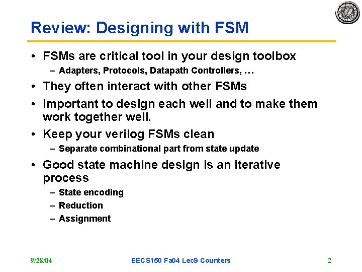
Review: Designing with FSM • FSMs are critical tool in your design toolbox – Adapters, Protocols, Datapath Controllers, … • They often interact with other FSMs • Important to design each well and to make them work together well. • Keep your verilog FSMs clean – Separate combinational part from state update • Good state machine design is an iterative process – State encoding – Reduction – Assignment 9/28/04 EECS 150 Fa 04 Lec 9 Counters 2
Outline • Review • Registers • Simple, important FSMs – Ring counters – Binary Counters • Universal Shift Register • Using Counters to build controllers – Different approach to FSM design 9/28/04 EECS 150 Fa 04 Lec 9 Counters 3
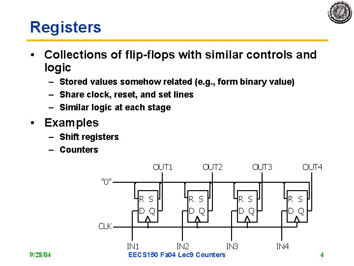
Registers • Collections of flip-flops with similar controls and logic – Stored values somehow related (e. g. , form binary value) – Share clock, reset, and set lines – Similar logic at each stage • Examples – Shift registers – Counters OUT 1 OUT 2 OUT 3 OUT 4 "0" R S D Q CLK IN 1 9/28/04 IN 2 EECS 150 Fa 04 Lec 9 Counters IN 3 IN 4 4
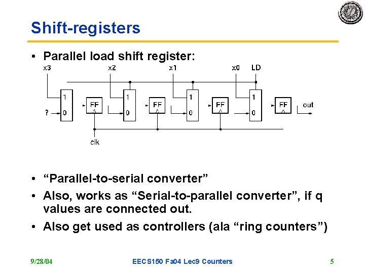
Shift-registers • Parallel load shift register: • “Parallel-to-serial converter” • Also, works as “Serial-to-parallel converter”, if q values are connected out. • Also get used as controllers (ala “ring counters”) 9/28/04 EECS 150 Fa 04 Lec 9 Counters 5
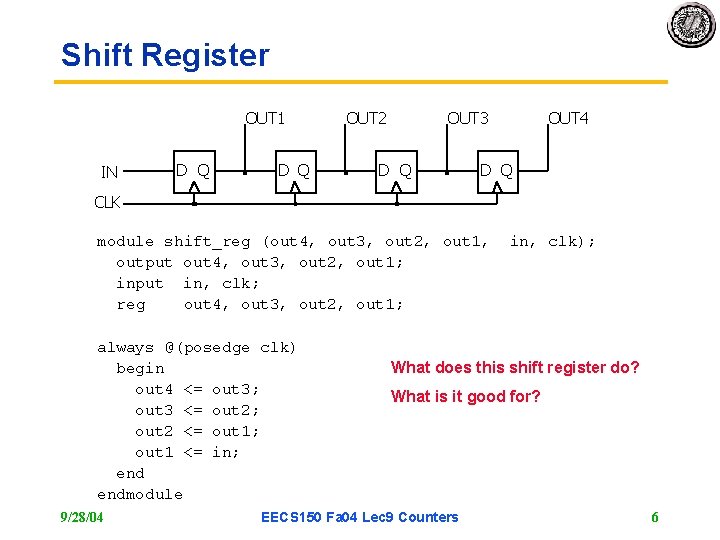
Shift Register OUT 1 IN D Q OUT 2 OUT 3 D Q OUT 4 D Q CLK module shift_reg (out 4, out 3, out 2, out 1, output out 4, out 3, out 2, out 1; input in, clk; reg out 4, out 3, out 2, out 1; always @(posedge clk) begin out 4 <= out 3; out 3 <= out 2; out 2 <= out 1; out 1 <= in; endmodule 9/28/04 in, clk); What does this shift register do? What is it good for? EECS 150 Fa 04 Lec 9 Counters 6
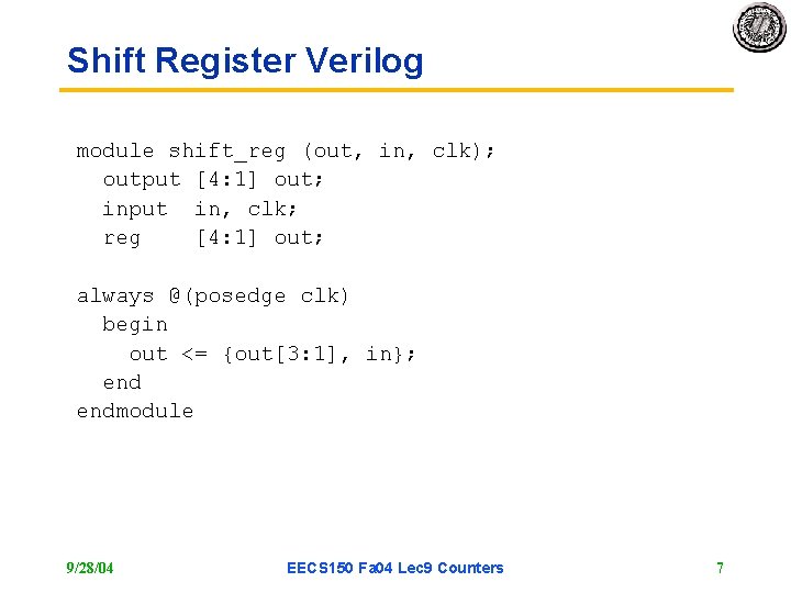
Shift Register Verilog module shift_reg (out, in, clk); output [4: 1] out; input in, clk; reg [4: 1] out; always @(posedge clk) begin out <= {out[3: 1], in}; endmodule 9/28/04 EECS 150 Fa 04 Lec 9 Counters 7
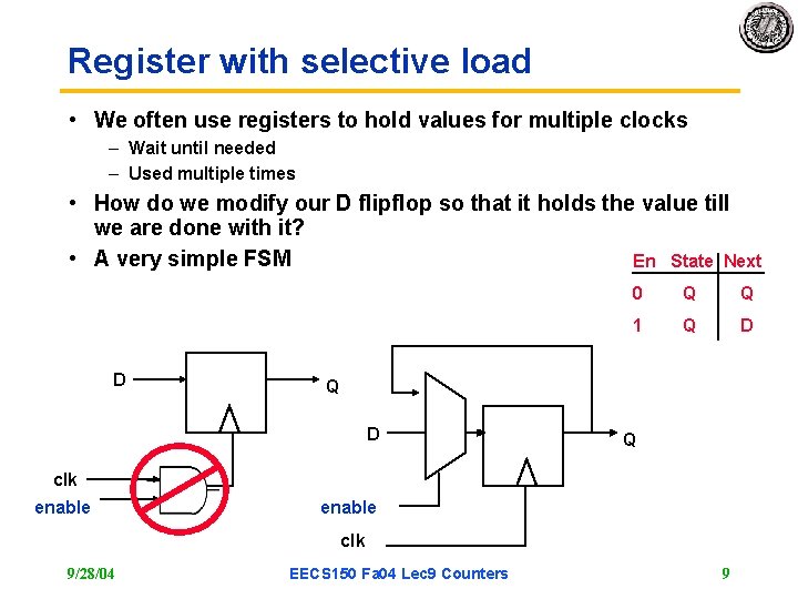
Register with selective load • We often use registers to hold values for multiple clocks – Wait until needed – Used multiple times • How do we modify our D flipflop so that it holds the value till we are done with it? • A very simple FSM En State Next D 0 Q Q 1 Q D Q clk enable clk 9/28/04 EECS 150 Fa 04 Lec 9 Counters 9
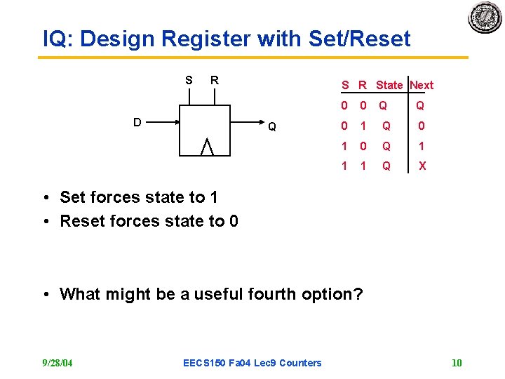
IQ: Design Register with Set/Reset S R D S R State Next Q 0 0 Q Q 0 1 0 Q 1 1 1 Q X • Set forces state to 1 • Reset forces state to 0 • What might be a useful fourth option? 9/28/04 EECS 150 Fa 04 Lec 9 Counters 10
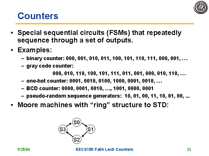
Counters • Special sequential circuits (FSMs) that repeatedly sequence through a set of outputs. • Examples: – binary counter: 000, 001, 010, 011, 100, 101, 110, 111, 000, 001, … – gray code counter: 000, 010, 100, 101, 111, 001, 000, 010, 110, … – one-hot counter: 0001, 0010, 0100, 1000, 0001, 0010, … – BCD counter: 0000, 0001, 0010, …, 1001, 0000, 0001 – pseudo-random sequence generators: 10, 01, 00, 11, 10, 01, 00, . . . • Moore machines with “ring” structure to STD: S 0 S 3 S 1 S 2 9/28/04 EECS 150 Fa 04 Lec 9 Counters 11
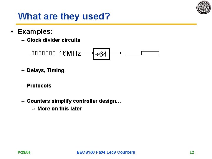
What are they used? • Examples: – Clock divider circuits 16 MHz 64 – Delays, Timing – Protocols – Counters simplify controller design… » More on this later 9/28/04 EECS 150 Fa 04 Lec 9 Counters 12
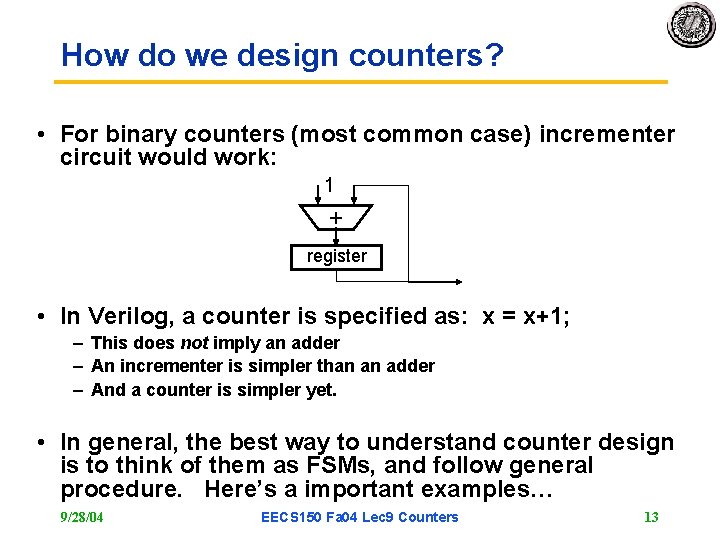
How do we design counters? • For binary counters (most common case) incrementer circuit would work: 1 + register • In Verilog, a counter is specified as: x = x+1; – This does not imply an adder – An incrementer is simpler than an adder – And a counter is simpler yet. • In general, the best way to understand counter design is to think of them as FSMs, and follow general procedure. Here’s a important examples… 9/28/04 EECS 150 Fa 04 Lec 9 Counters 13
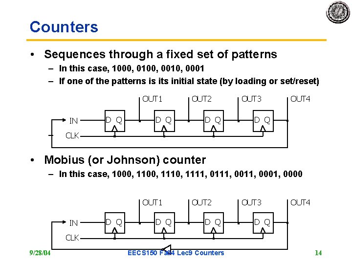
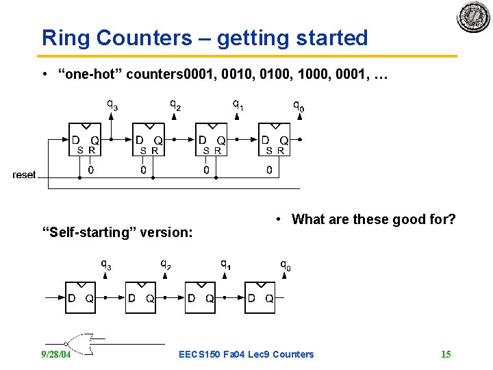
Counters • Sequences through a fixed set of patterns – In this case, 1000, 0100, 0010, 0001 – If one of the patterns is its initial state (by loading or set/reset) OUT 1 IN – D Q OUT 2 D Q OUT 3 OUT 4 D Q CLK • Mobius (or Johnson) counter – In this case, 1000, 1110, 1111, 0011, 0000 OUT 1 IN D Q OUT 2 D Q OUT 3 OUT 4 D Q CLK 9/28/04 EECS 150 Fa 04 Lec 9 Counters 14
Ring Counters – getting started • “one-hot” counters 0001, 0010, 0100, 1000, 0001, … “Self-starting” version: 9/28/04 • What are these good for? EECS 150 Fa 04 Lec 9 Counters 15
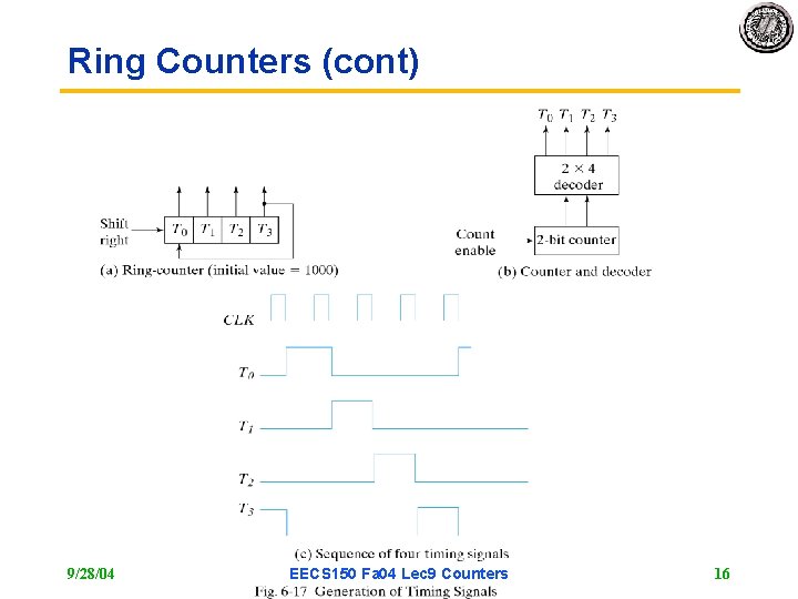
Ring Counters (cont) 9/28/04 EECS 150 Fa 04 Lec 9 Counters 16
Announcements • Reading: Katz 7. 1, 9. 1 -2 • Midterm Oct 7 (week from thurs) – Regular class time and location – Covers all material thru oct 5 » 10/5 lecture will be “putting it all together” • Review session evening of Oct 5 – See web page for specifics • HW 4 (current) is a good exercise • HW 5 (out thurs) will be light 9/28/04 EECS 150 Fa 04 Lec 9 Counters 17
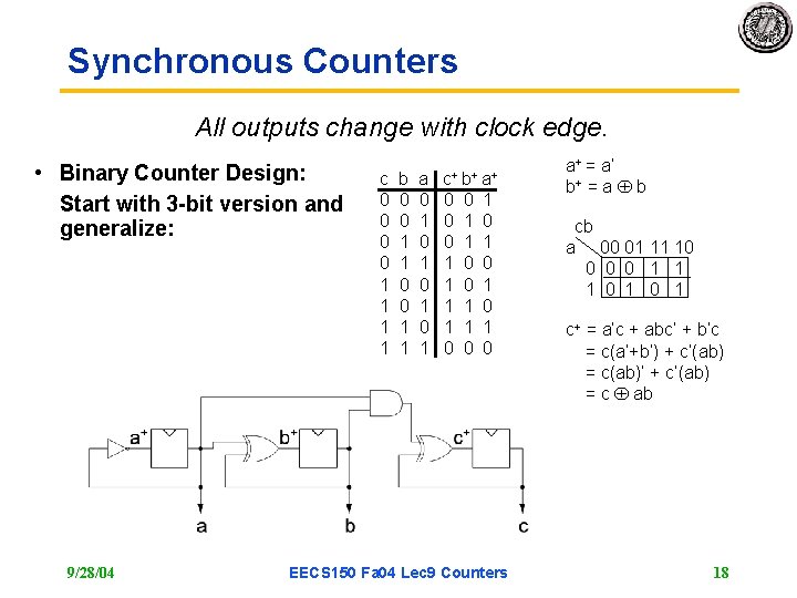
Synchronous Counters All outputs change with clock edge. • Binary Counter Design: Start with 3 -bit version and generalize: 9/28/04 c 0 0 1 1 b 0 0 1 1 a 0 1 0 1 c + b+ a+ 0 0 0 1 1 0 1 0 1 0 EECS 150 Fa 04 Lec 9 Counters a+ = a’ b+ = a b cb a 00 01 11 10 0 1 1 1 0 1 c+ = a’c + abc’ + b’c = c(a’+b’) + c’(ab) = c(ab)’ + c’(ab) = c ab 18
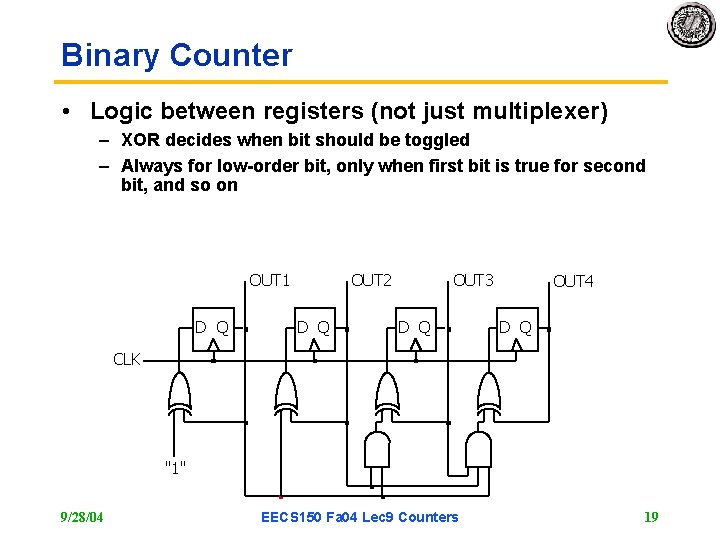
Binary Counter • Logic between registers (not just multiplexer) – XOR decides when bit should be toggled – Always for low-order bit, only when first bit is true for second bit, and so on OUT 1 D Q OUT 2 D Q OUT 3 D Q OUT 4 D Q CLK "1" 9/28/04 EECS 150 Fa 04 Lec 9 Counters 19
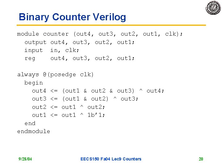
Binary Counter Verilog module counter (out 4, out 3, out 2, out 1, clk); output out 4, out 3, out 2, out 1; input in, clk; reg out 4, out 3, out 2, out 1; always @(posedge clk) begin out 4 <= (out 1 & out 2 & out 3) ^ out 4; out 3 <= (out 1 & out 2) ^ out 3; out 2 <= out 1 ^ out 2; out 1 <= out 1 ^ 1 b’ 1; endmodule 9/28/04 EECS 150 Fa 04 Lec 9 Counters 20
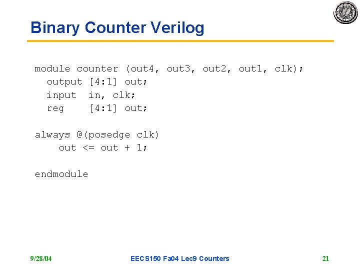
Binary Counter Verilog module counter (out 4, out 3, out 2, out 1, clk); output [4: 1] out; input in, clk; reg [4: 1] out; always @(posedge clk) out <= out + 1; endmodule 9/28/04 EECS 150 Fa 04 Lec 9 Counters 21
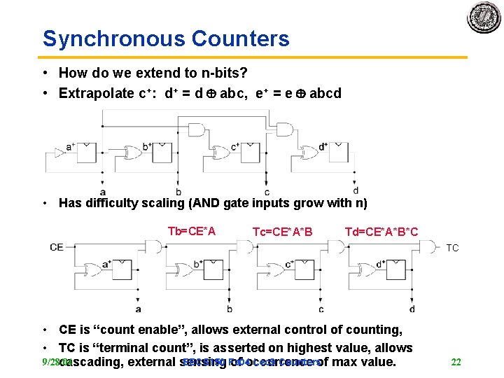
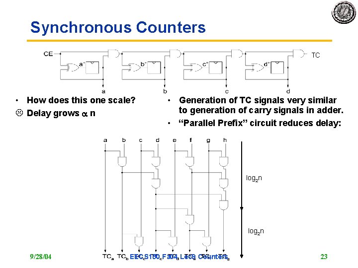
Synchronous Counters • How do we extend to n-bits? • Extrapolate c+: d+ = d abc, e+ = e abcd • Has difficulty scaling (AND gate inputs grow with n) Tb=CE*A Tc=CE*A*B Td=CE*A*B*C TC • CE is “count enable”, allows external control of counting, • TC is “terminal count”, is asserted on highest value, allows 9/28/04 EECS 150 Fa 04 Lec 9 Countersof max value. cascading, external sensing of occurrence 22
Synchronous Counters TC • How does this one scale? L Delay grows n • Generation of TC signals very similar to generation of carry signals in adder. • “Parallel Prefix” circuit reduces delay: log 2 n 9/28/04 EECS 150 Fa 04 Lec 9 Counters 23
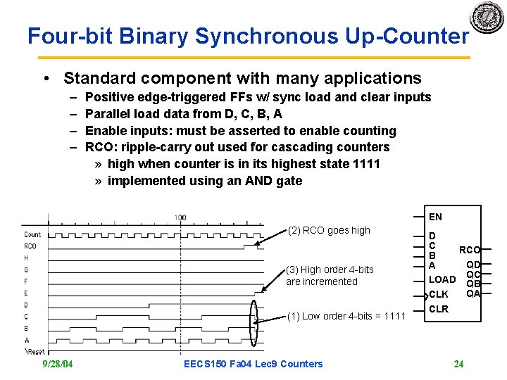
Four-bit Binary Synchronous Up-Counter • Standard component with many applications – – Positive edge-triggered FFs w/ sync load and clear inputs Parallel load data from D, C, B, A Enable inputs: must be asserted to enable counting RCO: ripple-carry out used for cascading counters » high when counter is in its highest state 1111 » implemented using an AND gate EN (2) RCO goes high (3) High order 4 -bits are incremented (1) Low order 4 -bits = 1111 9/28/04 EECS 150 Fa 04 Lec 9 Counters D C RCO B QD A QC LOAD QB QA CLK CLR 24
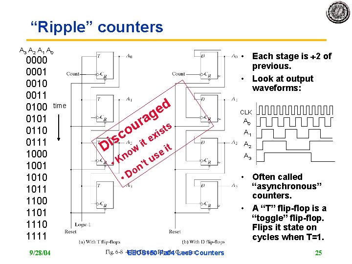
“Ripple” counters A 3 A 2 A 1 A 0 0001 0010 0011 0100 0101 0110 0111 1000 1001 1010 1011 1100 1101 1110 1111 9/28/04 • Each stage is 2 of previous. • Look at output waveforms: d e g a r ts u co exis time s i D it t ei ow s n u K t • ’ n o • D EECS 150 Fa 04 Lec 9 Counters CLK A 0 A 1 A 2 A 3 • Often called “asynchronous” counters. • A “T” flip-flop is a “toggle” flip-flop. Flips it state on cycles when T=1. 25
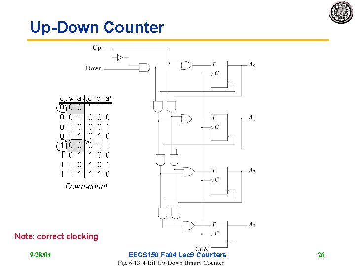
Up-Down Counter c 0 0 1 1 b 0 0 1 1 a 0 1 0 1 c + b+ a+ 1 1 1 0 0 0 1 1 1 0 0 1 1 1 0 Down-count Note: correct clocking 9/28/04 EECS 150 Fa 04 Lec 9 Counters 26
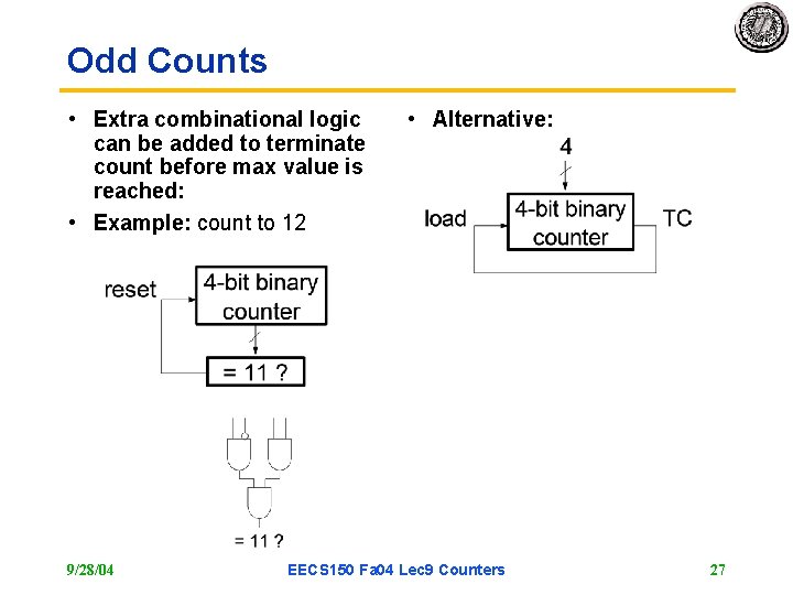
Odd Counts • Extra combinational logic can be added to terminate count before max value is reached: • Example: count to 12 9/28/04 • Alternative: EECS 150 Fa 04 Lec 9 Counters 27
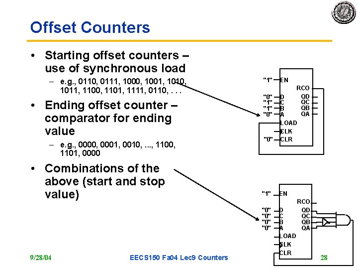
Offset Counters • Starting offset counters – use of synchronous load – e. g. , 0110, 0111, 1000, 1001, 1010, 1011, 1100, 1101, 1111, 0110, . . . • Ending offset counter – comparator for ending value – e. g. , 0000, 0001, 0010, . . . , 1100, 1101, 0000 • Combinations of the above (start and stop value) "1" "0" "1" "0" "0" 9/28/04 EECS 150 Fa 04 Lec 9 Counters EN RCO QD D QC C QB B QA A LOAD CLK CLR EN D C B A LOAD CLK CLR RCO QD QC QB QA 28
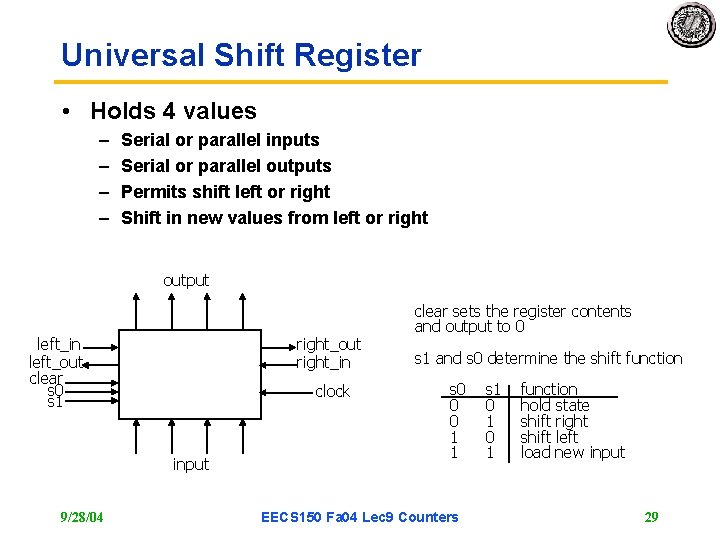
Universal Shift Register • Holds 4 values – – Serial or parallel inputs Serial or parallel outputs Permits shift left or right Shift in new values from left or right output left_in left_out clear s 0 s 1 right_out right_in clock input 9/28/04 clear sets the register contents and output to 0 s 1 and s 0 determine the shift function s 0 0 0 1 1 EECS 150 Fa 04 Lec 9 Counters s 1 0 1 function hold state shift right shift left load new input 29
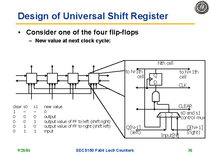
Design of Universal Shift Register • Consider one of the four flip-flops – New value at next clock cycle: Nth cell to N-1 th cell clear 1 0 0 s 0 – 0 0 1 1 9/28/04 s 1 – 0 1 new value 0 output value of FF to left (shift right) output value of FF to right (shift left) input to N+1 th cell Q D CLK CLEAR 0 1 2 3 s 0 and s 1 control mux Q[N-1] (left) EECS 150 Fa 04 Lec 9 Counters Input[N] Q[N+1] (right) 30
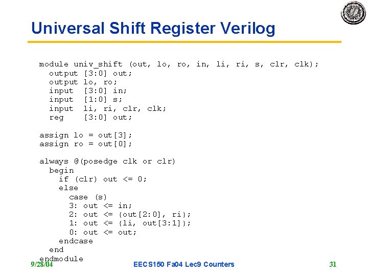
Universal Shift Register Verilog module univ_shift (out, lo, ro, in, li, ri, s, clr, clk); output [3: 0] out; output lo, ro; input [3: 0] in; input [1: 0] s; input li, ri, clr, clk; reg [3: 0] out; assign lo = out[3]; assign ro = out[0]; always @(posedge clk or clr) begin if (clr) out <= 0; else case (s) 3: out <= in; 2: out <= {out[2: 0], ri}; 1: out <= {li, out[3: 1]}; 0: out <= out; endcase endmodule 9/28/04 EECS 150 Fa 04 Lec 9 Counters 31
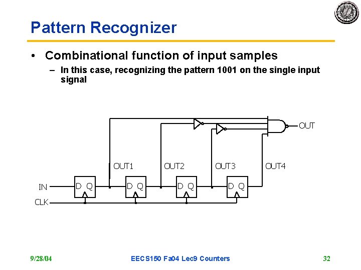
Pattern Recognizer • Combinational function of input samples – In this case, recognizing the pattern 1001 on the single input signal OUT 1 IN D Q OUT 2 D Q OUT 3 OUT 4 D Q CLK 9/28/04 EECS 150 Fa 04 Lec 9 Counters 32
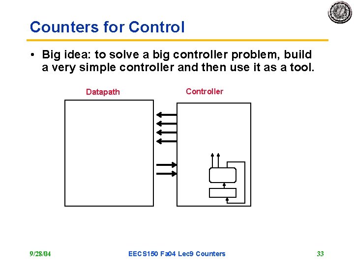
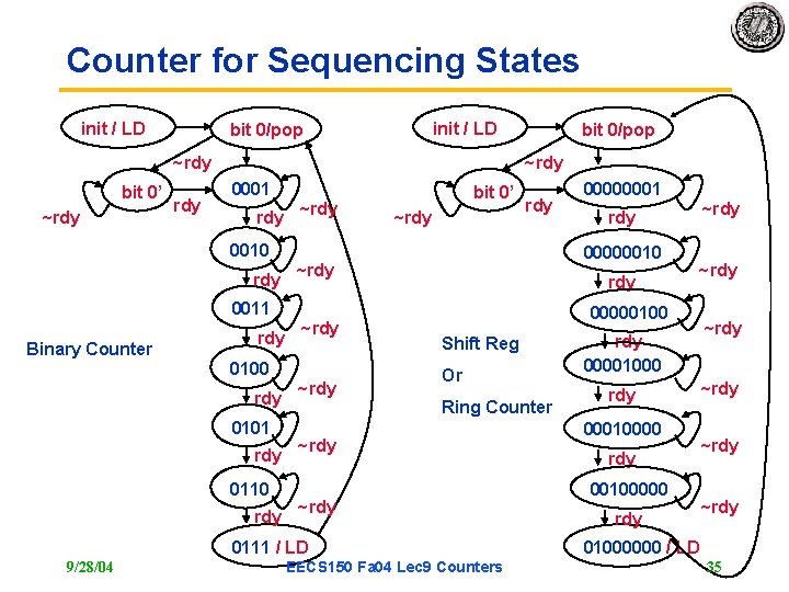
Counters for Control • Big idea: to solve a big controller problem, build a very simple controller and then use it as a tool. Datapath 9/28/04 Controller EECS 150 Fa 04 Lec 9 Counters 33
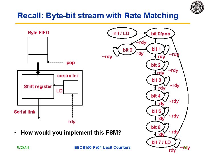
Recall: Byte-bit stream with Rate Matching Byte FIFO init / LD bit 0/pop ~rdy bit 0’ ~rdy pop controller Shift register rdy bit 1 rdy bit 2 rdy bit 3 rdy LD bit 4 rdy bit 5 Serial link rdy • How would you implement this FSM? rdy bit 6 rdy ~rdy ~rdy bit 7 / LD 9/28/04 EECS 150 Fa 04 Lec 9 Counters rdy 34 ~rdy
Counter for Sequencing States init / LD bit 0/pop ~rdy bit 0’ ~rdy 0001 rdy 0010 rdy 0011 Binary Counter rdy 0100 rdy 0101 rdy 0110 rdy ~rdy bit 0’ ~rdy 00000001 ~rdy 00000010 ~rdy 00000100 Shift Reg Or Ring Counter ~rdy 0111 / LD 9/28/04 bit 0/pop EECS 150 Fa 04 Lec 9 Counters rdy 00001000 rdy 00010000 rdy 00100000 rdy ~rdy 01000000 / LD 35
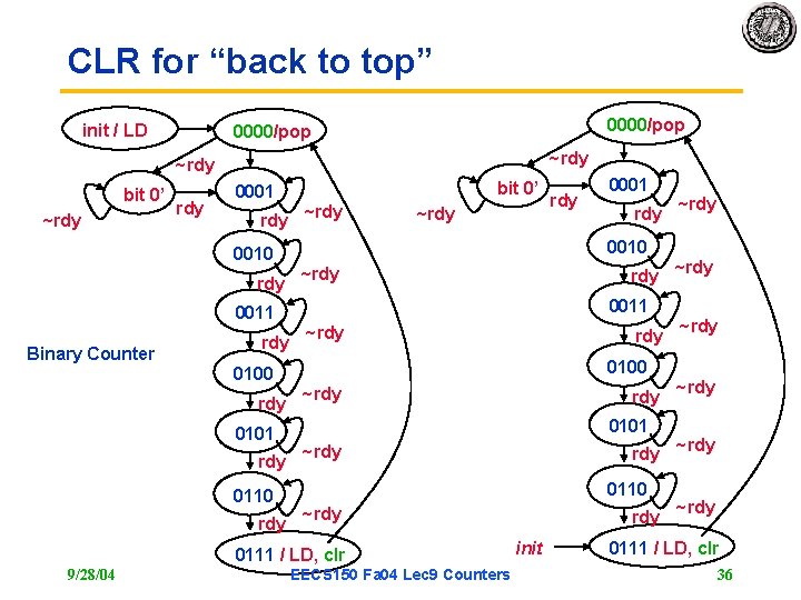
CLR for “back to top” init / LD 0000/pop ~rdy bit 0’ ~rdy 0001 rdy 0010 rdy 0011 Binary Counter rdy 0100 rdy 0101 rdy 0110 rdy bit 0’ ~rdy rdy 0010 ~rdy 0011 ~rdy 0100 ~rdy 0101 ~rdy 0110 ~rdy 0111 / LD, clr 9/28/04 rdy 0001 EECS 150 Fa 04 Lec 9 Counters rdy init ~rdy ~rdy 0111 / LD, clr 36
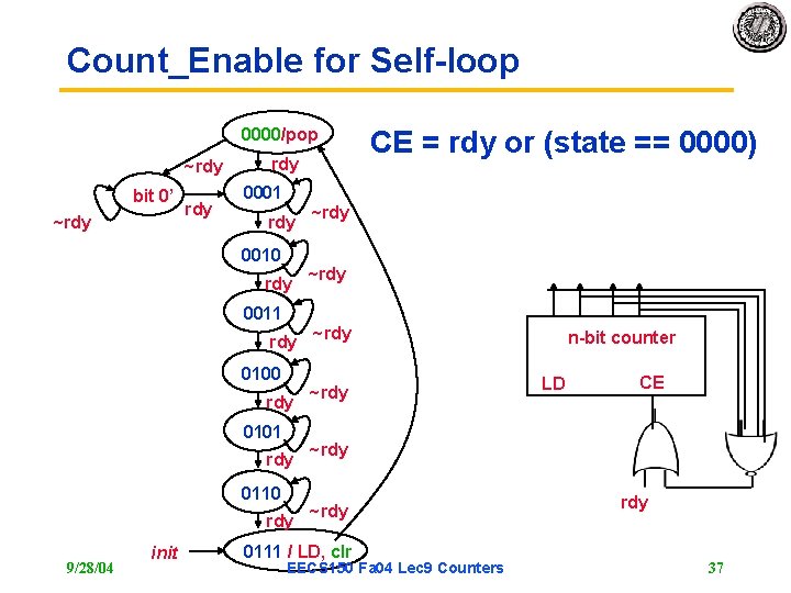
Count_Enable for Self-loop 0000/pop ~rdy bit 0’ ~rdy rdy 0001 rdy 0010 rdy 0011 rdy 0100 rdy 0101 rdy 0110 rdy 9/28/04 init CE = rdy or (state == 0000) ~rdy n-bit counter LD CE ~rdy 0111 / LD, clr EECS 150 Fa 04 Lec 9 Counters rdy 37
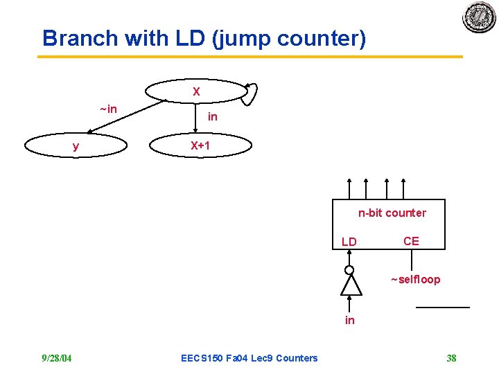
Branch with LD (jump counter) X ~in y in X+1 n-bit counter LD CE ~selfloop in 9/28/04 EECS 150 Fa 04 Lec 9 Counters 38
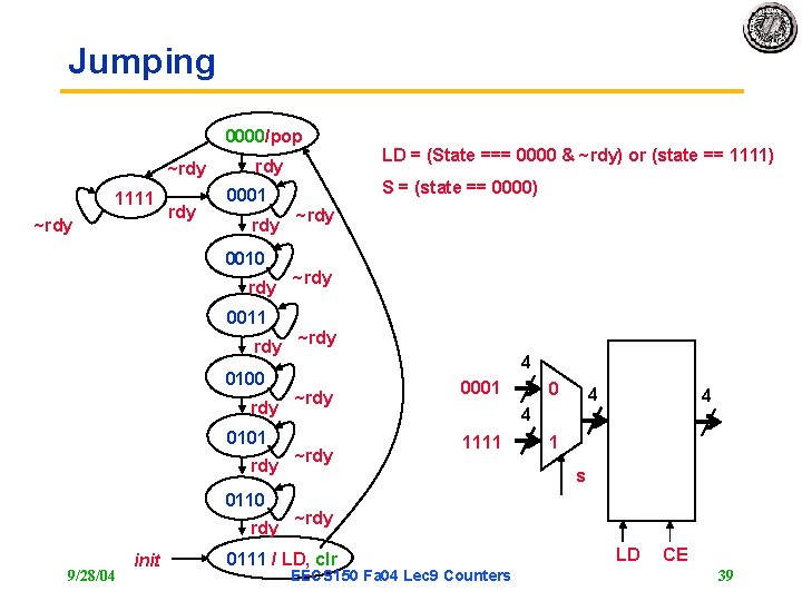
Jumping 0000/pop ~rdy 1111 ~rdy rdy 0001 rdy 0010 rdy 0011 rdy 0100 rdy 0101 rdy 0110 rdy 9/28/04 init LD = (State === 0000 & ~rdy) or (state == 1111) S = (state == 0000) ~rdy 4 ~rdy 0001 0 4 4 4 1111 1 s ~rdy 0111 / LD, clr EECS 150 Fa 04 Lec 9 Counters LD CE 39
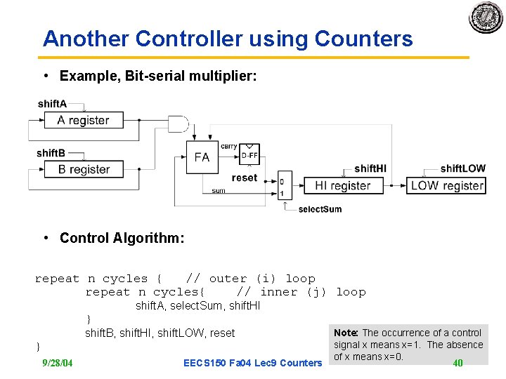
Another Controller using Counters • Example, Bit-serial multiplier: • Control Algorithm: repeat n cycles { // outer (i) loop repeat n cycles{ // inner (j) loop shift. A, select. Sum, shift. HI } shift. B, shift. HI, shift. LOW, reset } 9/28/04 EECS 150 Fa 04 Lec 9 Counters Note: The occurrence of a control signal x means x=1. The absence of x means x=0. 40
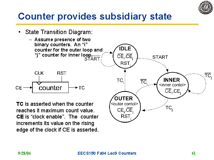
Counter provides subsidiary state • State Transition Diagram: – Assume presence of two binary counters. An “i” counter for the outer loop and “j” counter for inner loop. TC is asserted when the counter reaches it maximum count value. CE is “clock enable”. The counter increments its value on the rising edge of the clock if CE is asserted. 9/28/04 EECS 150 Fa 04 Lec 9 Counters 41
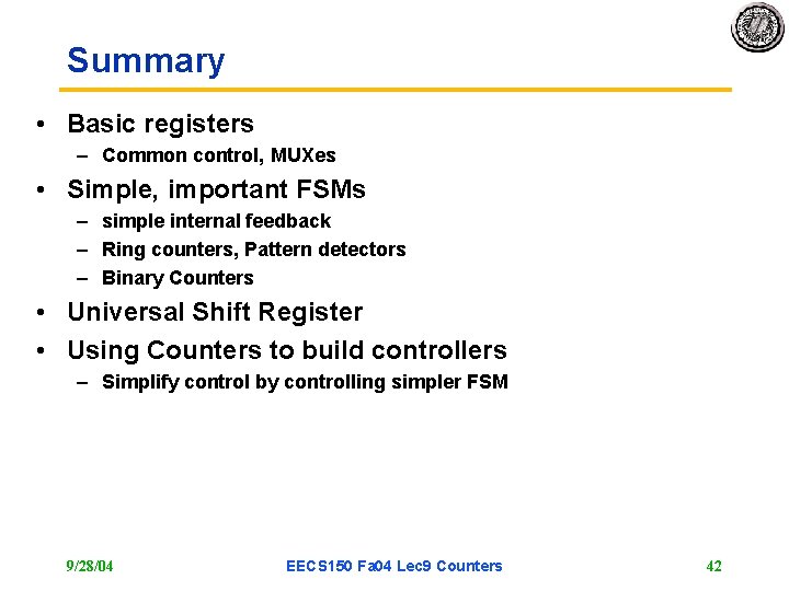
Summary • Basic registers – Common control, MUXes • Simple, important FSMs – simple internal feedback – Ring counters, Pattern detectors – Binary Counters • Universal Shift Register • Using Counters to build controllers – Simplify control by controlling simpler FSM 9/28/04 EECS 150 Fa 04 Lec 9 Counters 42