EECE 311 Electronic Circuits Part 4 OPERATIONAL AMPLIFIER


- Slides: 26
EECE 311: Electronic Circuits Part 4
OPERATIONAL AMPLIFIER 2
n Ideal Op-Amp n n Open loop gain Infinite input impedance Zero output impedance Infinite open-loop gain Infinite bandwidth … n …
n Inverting Amplifier Configuration n n Input and output signals out of phase Trade-off between a large input resistance and a large gain
¨ Effect of Finite Open-Loop Gain
n Summing Amplifier
n Non-Inverting Amplifier Configuration n n Infinite input resistance Input and output signals in-phase
n Voltage Follower n n n Infinite input resistance Zero output resistance Input and output signals are equal
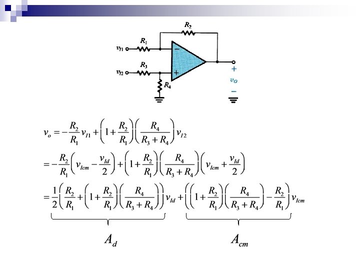
n Difference Amplifier: Amplify the difference of two signals Two input signals: let Difference signal Common-mode
n Difference Amplifier: Amplify the difference of two signals Two input signals:
Common-Mode Rejection Ratio In a differential amplifier, Acm is ideally zero and CMRR is ideally infinite 11
Op-Amp Difference Amplifier Circuit 12
By superposition:
For the difference amplifier, the output should be a function of v. ID only. For the difference amplifier, Acm should be zero:
n Effect of Finite Bandwidth n fb = f 3 d. B is made very low to stabilize the op-amp
¨ Frequency Response of the Inverting Op-Amp
¨ Frequency Response of the Inverting Op-Amp n Example: R 2/R 1 = 10
n Large-Signal Operation of Op-Amps ¨ Output Voltage Saturation The op-amp output voltage saturates within 1 V of the power supplies voltages (rail-to-rail op-amps reach to within a few m. V) ¨ Output Current Limits Output current limited to a few m. A (or few tens of m. A, usually 20 m. A) in either direction (source or sink)
¨ Slew Rate There is a maximum rate of change possible at the output of the op-amp.
¨ Slew Rate For a voltage follower: For a step input V: Slew-rate distortion if dvo/dt > SR
¨ Full-Power Bandwidth The output of the op-amp can be slew rate limited or frequency limited. It is slew rate limited when (for a sinusoidal input): Frequency at which op amp stops behaving linearly n Example:
n Op-Amp Integrator and Differentiator Integrator: Differentiator:
¨ Op-Amp Integrator
¨ Op-Amp Differentiator
Simple CMOS Op-Amp