
EE 8402 TRANSMISSION AND DISTRIBUTION OBJECTIVE To become
EE 8402 TRANSMISSION AND DISTRIBUTION
OBJECTIVE • To become familiar with the function of different components Distribution used levels in of Transmission power modeling of these components. systems and
OBJECTIVES • • • To develop expression for computation of fundamental parameters of lines. To categorize the lines into different classes and develop equivalent circuits for these classes. To analyse the voltage distribution in insulator strings and cables and methods to improve the same.
INTRODUCTION
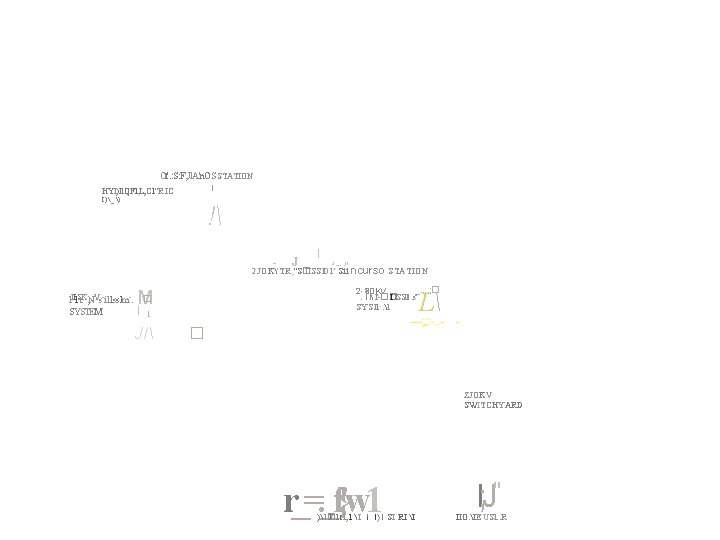
INTRODUCTION Of. : S: F, Jl. A'n. OS STATION [ HYl)ll. QFl, L; Cl"R IC I)_) ! - J I &, ; , , . . ; II 2 JOK'TR, "S� IISSl 01' Sii 1 II 1 St. K, NVs-i 11 ss 1 m-. SYSTEM _. . ; � 2 30 KV l'-�� IJSSIO: s' SYS'll·. 1 : fl � M I 1 JI - ncurso STATION L -----; ; : : -. . . - - � ZJOKV SWITCHYARD r_=. _f}w 1 ) l� lf l tl, : 1 I l' l ) l SI RI I l; J" IIO. IE USl: . R
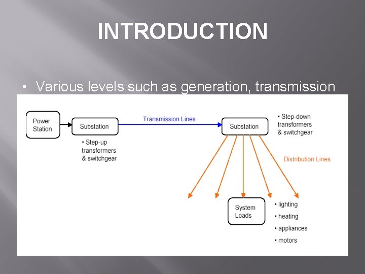
INTRODUCTION • Various levels such as generation, transmission and distribution.
INTRODUCTION • HVDC High voltage direct current (HVDC) is used to transmit large amounts of power over long distances or for interconnections between asynchronous grids. When electrical energy is required to be transmitted over very long distances, it is more economical to transmit using direct current instead of alternating current.
INTRODUCTION • EHV AC transmission Hydro-electric and coal or oil-fired stations are located very far from load centres for various reasons which requires the transmission of the generated electric power over very long distances. This requires very high voltages for transmission. The very rapid strides taken by development of dc transmission since 1950 is playing a major role in extra-longdistance transmission, complementing or supplementing EHV AC transmission.
INTRODUCTION Technical performance and reliability Considerations in the design of a power line: • • The amount of active power it has to transmit • • The distance over which the power must be carried • • The cost of the power line • • Aesthetic considerations, urban congestion, ease of installation, expected load growth
INTRODUCTION • Application of HVDC transmission system • HVDC Light, is utilising state of the art semiconductors, control and cable insulation and can offer many new transmission opportunities as has been demonstrated by actual projects above. It offers a lot of possibilities to enhance the power systems. • Wind power, even big parks, can easily be connected to the grid. In many cases HVDC Light can give new opportunities to trade electric energy in the new deregulated markets. • As HVDC Light has been developed to minimise environmental impact and impact on the connecting grids, the licence procedure is generally more favourable than more traditional solutions.
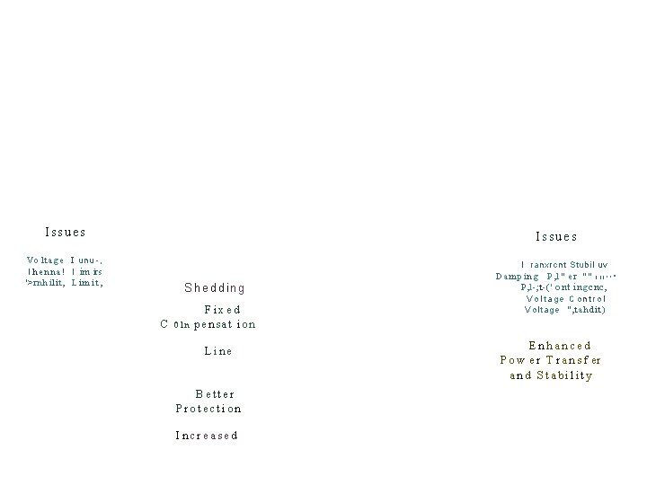
INTRODUCTION • FACTS Issues Vo lt a g e I un u -, I h e n n a ! I im irs '>rnhilit, L i m i t , I ranxrcnt Stubil uv Shedding C 01 n Fixed pensat ion Line Better Protection Increased Damping P, l" er "" I l l ! ! " P, l-; t-(' ont ingcnc, Voltage Control V o l t a g e " , tah d i t) Enhanced P o w e r T r a n s f er and Stability
INTRODUCTION • TCSC The Thyristor Controlled Series Capacitor (TCSC) seems to be one of the members within the FACTS family, beside the SVC that was established long ago, which has attracted the most interest so far. One reason may be that a distinctive quality of the TCSC concept is that it uses an extremely simple main circuit topology. The capacitor is inserted directly in series with the transmission line and the thyristor controlled inductor is mounted directly in parallel with the capacitor. Thus no interfacing equipment like e. g. high voltage transformers is required. This makes TCSC much more economical than some other competing FACTS technologies.
INTRODUCTION • SVC • Static variable capacitor Parallel-connected static var generator or absorber Output is adjusted to exchange capacitive or inductive current. Maintain or control specific parameters of the electrical power system (typically bus voltage). Thyristor-based Controllers Lower cost alternative to STATCOM
INTRODUCTION • STATCOM Static Synchronous Compensator (STATCOM) • Parallel-connected static var compensator • Capacitive or inductive output current controlled independently of the ac system voltage
INTRODUCTION • UPFC Unified power flow controller (UPFC) is one of the FACTS devices, which can control power system parameters such as terminal voltage, line impedance and phase angle. Therefore, it can be used not only for power flow control, but also for power system stabilizing control.
TRANSMISSION LINE PARAMETERS Parameters in the transmission line resistance r, inductance L, capacitance C L and C are due to the effects of magnetic and electric fields around the conductor Overhead transmission line ANSI voltage standard: 69 k. V, 115 k. V, 138 k. V, 161 k. V, 230 k. V, 345 k. V, 500 k. V, 765 k. V line-to-line extra-high-voltage (EHV): >230 k. V, ultra-high-voltage (UHV): 765 k. V bundling: use more than one conductor per phase, usually used at voltage > 230 k. V advantage of bundling: increase effective radius of line conductor, reduce electric field strength and reduces corona power loss, audio loss and radio interference, and reduces line reactance Energy Conversion Lab
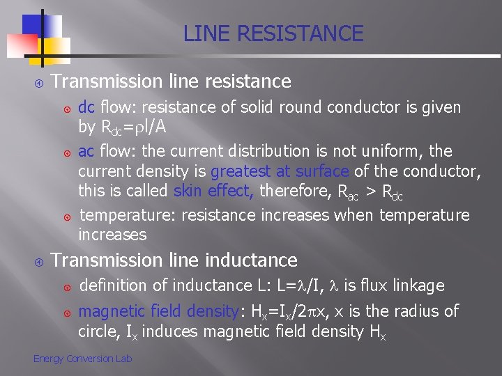
LINE RESISTANCE Transmission line resistance dc flow: resistance of solid round conductor is given by Rdc= l/A ac flow: the current distribution is not uniform, the current density is greatest at surface of the conductor, this is called skin effect, therefore, Rac > Rdc temperature: resistance increases when temperature increases Transmission line inductance definition of inductance L: L= /I, is flux linkage magnetic field density: Hx=Ix/2 x, x is the radius of circle, Ix induces magnetic field density Hx Energy Conversion Lab
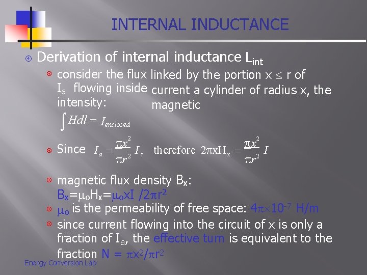
INTERNAL INDUCTANCE Derivation of internal inductance Lint consider the flux linked by the portion x r of Ia flowing inside current a cylinder of radius x, the intensity: magnetic Hdl Ienclosed x 2 x Since I a 2 I , therefore 2 x. H x 2 I r r magnetic flux density Bx: 2 Bx= o. Hx= ox. I /2 r 2 o is the permeability of free space: 4 10 -7 H/m since current flowing into the circuit of x is only a fraction of Ia, the effective turn is equivalent to the fraction N = x 2/ r 2 Energy Conversion Lab
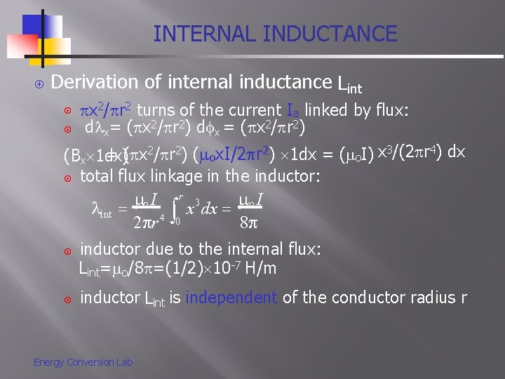
INTERNAL INDUCTANCE Derivation of internal inductance Lint x 2/ r 2 turns of the current Ia linked by flux: d x= ( x 2/ r 2) d x = ( x 2/ r 2) ( ox. I/2 r 2) 1 dx = ( o. I) x 3/(2 r 4) dx (Bx 1 dx) total flux linkage in the inductor: r o I 3 o. I x dx int 2 r 4 0 8 inductor due to the internal flux: Lint= o/8 =(1/2) 10 -7 H/m inductor Lint is independent of the conductor radius r Energy Conversion Lab
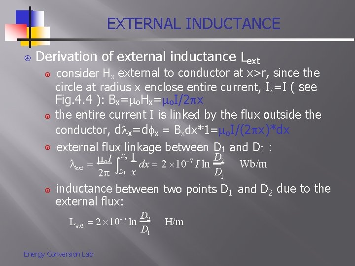
EXTERNAL INDUCTANCE Derivation of external inductance Lext consider Hx external to conductor at x>r, since the circle at radius x enclose entire current, Ix=I ( see Fig. 4. 4 ): Bx= o. Hx= o. I/2 x the entire current I is linked by the flux outside the conductor, d x=d x = Bxdx*1= o. I/(2 x)*dx external flux linkage between D 1 and D 2 : D 1 D 2 o. I 7 dx 2 10 I ln Wb/m ext D 1 2 D x inductance between two points D 1 and D 2 due to the external flux: 2 1 Lext D 2 2 10 ln D 1 Energy Conversion Lab 7 H/m
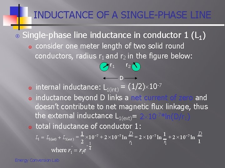
INDUCTANCE OF A SINGLE-PHASE LINE Single-phase line inductance in conductor 1 (L 1) consider one meter length of two solid round conductors, radius r 1 and r 2 in the figure below: r 1 r 2 D internal inductance: L 1(int) = (1/2) 10 -7 inductance beyond D links a net current of zero and doesn’t contribute to net magnetic flux linkage, thus the external inductance L 1(ext)= 2 10 -7*ln(D/r 1) total inductance of conductor 1: L 1(int) L 1(ext ) ' 1 1 D D 10 7 2 10 7 ln 1' 2 10 7 ln 1 r 1 2 1 r 1 where r r 1 e Energy Conversion Lab 4
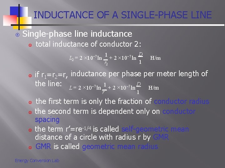
INDUCTANCE OF A SINGLE-PHASE LINE Single-phase line inductance total inductance of conductor 2: L 2 2 10 7 ln 1 7 D 2 10 ln ' 1 r 2 if r 1=r 2=r, inductance per phase per meter length of the line: L 2 10 7 ln 1 2 10 7 ln D H/m r' H/m 1 the first term is only the fraction of conductor radius the second term is dependent only on conductor spacing the term r’=re-1/4 is called self-geometric mean distance of a circle with radius r by GMR is called geometric mean radius Energy Conversion Lab
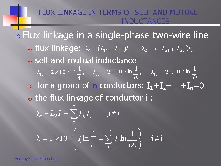
FLUX LINKAGE IN TERMS OF SELF AND MUTUAL INDUCTANCES Flux linkage in a single-phase two-wire line flux linkage: 1 (L 11 L 12 )I 1 2 ( L 21 L 22 )I 2 self and mutual inductance: L 11 2 10 7 ln 1 , ' r 1 L 22 2 10 7 ln 1 , ' r 2 L 12 2 10 7 ln 1 D for a group of n conductors: I 1+I 2+…+In=0 the flux linkage of conductor i : n i Lii Ii Lij I j j i j 1 n 1 1 7 i 2 10 Ii ln ' I j ln r D j 1 i ij Energy Conversion Lab j i
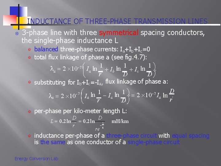
INDUCTANCE OF THREE-PHASE TRANSMISSION LINES 3 -phase line with three symmetrical spacing conductors, the single-phase inductance L balanced three-phase currents: Ia+Ib+Ic=0 total flux linkage of phase a (see fig. 4. 7): a 2 10 7 Ia ln 1' I b ln 1 I c ln 1 r D D substituting for Ib+Ic=-Ia, flux linkage of phase a: D 1 ln 1 7 ln Ia 2 10 Ia ln ' a 2 10 Ia ' r r D 7 per-phase per kilo-meter length L: L 0. 2 ln D D 0. 2 ln 1 r' re 4 m. H/km inductance per-phase of a three-phase circuit with equal spacing is the same as one conductor of a single-phase circuit Energy Conversion Lab
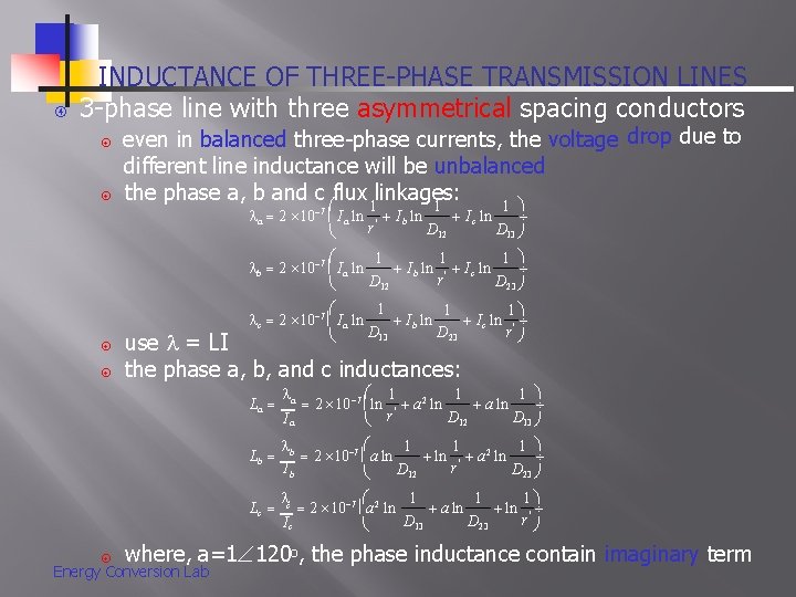
INDUCTANCE OF THREE-PHASE TRANSMISSION LINES 3 -phase line with three asymmetrical spacing conductors even in balanced three-phase currents, the voltage drop due to different line inductance will be unbalanced the phase a, b and c flux 1 linkages: 1 1 a 2 10 7 I a ln D 13 1 1 1 I b ln ' I c ln r D 12 D 23 c 2 10 7 I a ln I c ln b 2 10 7 I a ln I b ln r' D 12 1 1 1 I c ln ' I b ln D 13 D 23 r use = LI the phase a, b, and c inductances: La a 1 1 1 2 10 7 ln ' a 2 ln a ln r D D Ia 13 12 b 1 1 1 2 10 7 a ln ' a 2 ln Ib r D D 23 12 1 1 1 Lc c 2 10 7 a 2 ln ' a ln r D 13 D 23 Ic Lb where, a=1 120 o, the phase inductance contain imaginary term Energy Conversion Lab
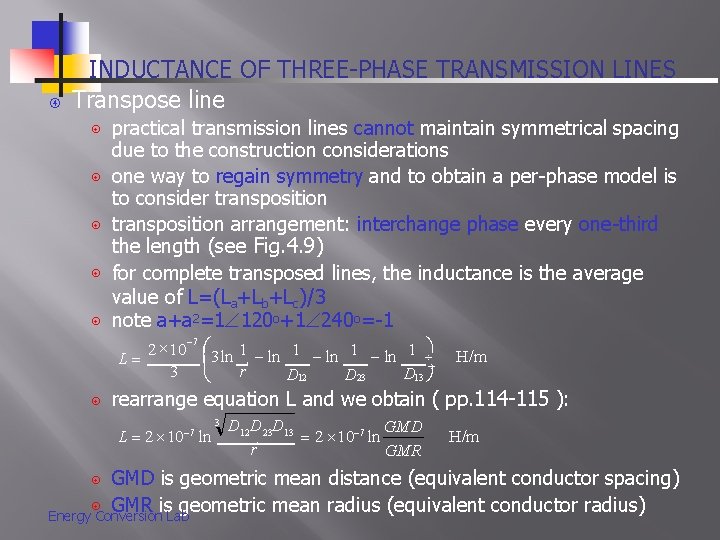
INDUCTANCE OF THREE-PHASE TRANSMISSION LINES Transpose line practical transmission lines cannot maintain symmetrical spacing due to the construction considerations one way to regain symmetry and to obtain a per-phase model is to consider transposition arrangement: interchange phase every one-third the length (see Fig. 4. 9) for complete transposed lines, the inductance is the average value of L=(La+Lb+Lc)/3 note a+a 2=1 120 o+1 240 o=-1 2 10 L 3 7 1 ln 1 3 ln r' D 13 D 12 D 23 H/m rearrange equation L and we obtain ( pp. 114 -115 ): L 2 10 ln 7 3 D 12 D 23 D 13 GMD 7 2 10 ln r' GMR H/m GMD is geometric mean distance (equivalent conductor spacing) GMR is geometric mean radius (equivalent conductor radius) Energy Conversion Lab
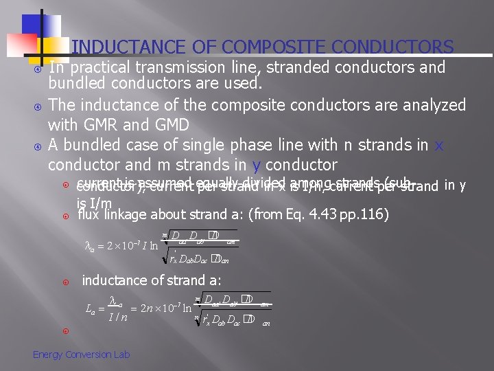
INDUCTANCE OF COMPOSITE CONDUCTORS In practical transmission line, stranded conductors and bundled conductors are used. The inductance of the composite conductors are analyzed with GMR and GMD A bundled case of single phase line with n strands in x conductor and m strands in y conductor current is assumed divided among strandsper (subconductor), current equally per strand in x is I/n, current strand in y is I/m flux linkage about strand a: (from Eq. 4. 43 pp. 116) a 2 10 I ln 7 m Daa ' Dab' � D am ' rx Dab. Dac � Dan inductance of strand a: La a I/n Energy Conversion Lab 2 n 10 ln 7 m Daa' Dab' � D am n rx' Dab Dac � D an
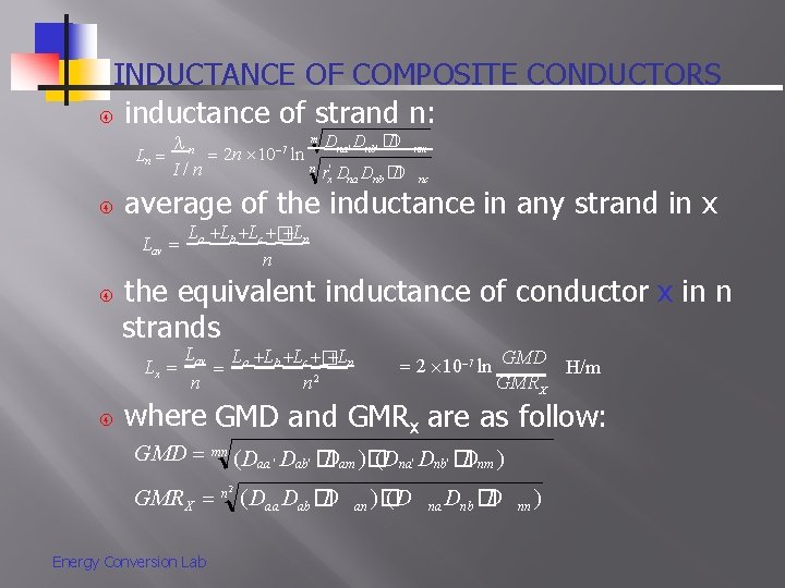
INDUCTANCE OF COMPOSITE CONDUCTORS inductance of strand n: Ln n I/n Dna ' Dnb' � D nm n rx' Dna Dnb � D nc La Lb Lc � Ln n the equivalent inductance of conductor x in n strands Lx m average of the inductance in any strand in x Lav 2 n 10 ln 7 Lav La Lb Lc � Ln n 2 n 2 10 7 ln GMD H/m GMR X where GMD and GMRx are as follow: GMD mn (Daa ' Dab' � Dam )� (Dna' Dnb' � Dnm ) GMR X Energy Conversion Lab n 2 D (Daa Dab � an )� (D na Dnb � D nn )
GMD AND GMR OF COMPOSITE CONDUCTORS Definition of GMD: mn th root of D’s product about any strand in x to strands in y Definition of GMRX: nn th root of rx’ product about any strand in x to the other strands in x GMR of the seven identical strands in a conductor see example 4. 1 a large number of strands in GMR calculation would be tedious, usually GMRs are available in manufacturer’s data Energy Conversion Lab
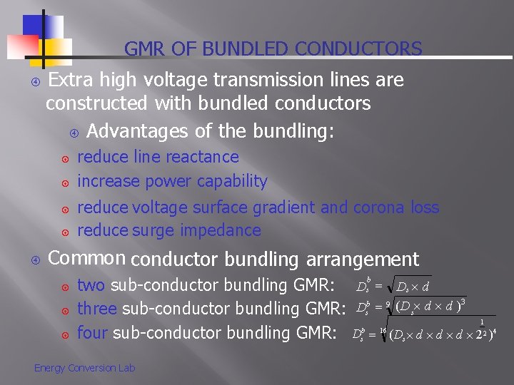
GMR OF BUNDLED CONDUCTORS Extra high voltage transmission lines are constructed with bundled conductors Advantages of the bundling: reduce line reactance increase power capability reduce voltage surface gradient and corona loss reduce surge impedance Common conductor bundling arrangement two sub-conductor bundling GMR: Dsb Ds d b 9 (D d d )3 D three sub-conductor bundling GMR: s s 1 16 b four sub-conductor bundling GMR: Ds (Ds d d d 22 )4 Energy Conversion Lab
INDUCTANCE OF THREE-PHASE DOUBLE CIRCUIT A three phase double circuit line consists of two identical three-phase circuits The circuits are operated with a 1 -a 2, b 1 -b 2, c 1 -c 2 in parallel as figure 4. 13 Geometric arrangement of three-phase double circuit unbalanced with different spacing, cause unbalanced voltage drop to achieve balance, use transpose arrangement To obtain inductance of three-phase double circuit line, we must consider transpose effect of L consider bundle effect of L combine transpose and bundle effects together Energy Conversion Lab
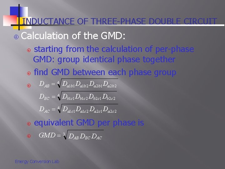
INDUCTANCE OF THREE-PHASE DOUBLE CIRCUIT Calculation of the GMD: starting from the calculation of per-phase GMD: group identical phase together find GMD between each phase group DAB 4 Da 1 b 1 Da 1 b 2 Da 2 b 1 Da 2 b 2 DBC 4 Db 1 c 1 Db 1 c 2 Db 2 c 1 Db 2 c 2 DAC 4 Da 1 c 1 Da 1 c 2 Da 2 c 1 Da 2 c 2 equivalent GMD per phase is GMD 3 DAB DBC DAC Energy Conversion Lab
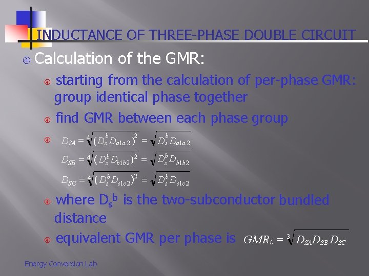
INDUCTANCE OF THREE-PHASE DOUBLE CIRCUIT Calculation of the GMR: starting from the calculation of per-phase GMR: group identical phase together find GMR between each phase group b b 2 DSA 4 (Ds Da 1 a 2 ) Ds Da 1 a 2 DSB 4 (Dsb Db 1 b 2 )2 Dsb Db 1 b 2 DSC 4 (Dsb Dc 1 c 2 )2 Dsb Dc 1 c 2 where Dsb is the two-subconductor bundled distance 3 equivalent GMR per phase is GMRL DSADSB DSC Energy Conversion Lab
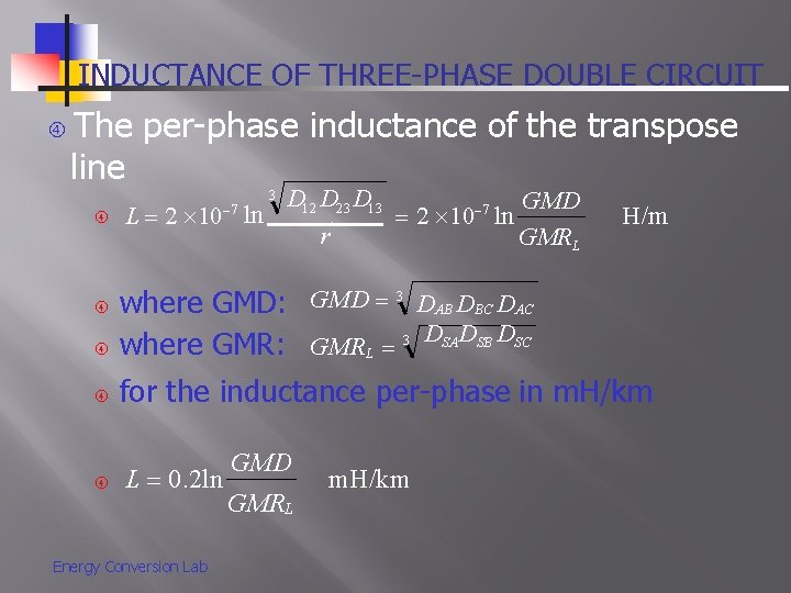
INDUCTANCE OF THREE-PHASE DOUBLE CIRCUIT The per-phase inductance of the transpose line L 2 10 ln 7 3 D 12 D 23 D 13 GMD 7 2 10 ln r' GMRL H/m where GMD: GMD 3 DAB DBC DAC where GMR: GMRL 3 DSADSB DSC for the inductance per-phase in m. H/km L 0. 2 ln Energy Conversion Lab GMD GMRL m. H/km
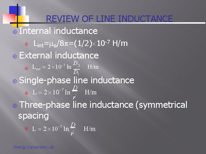
REVIEW OF LINE INDUCTANCE Internal inductance External inductance Lext D 2 2 10 ln D 1 7 H/m Single-phase line inductance Lint= o/8 =(1/2) 10 -7 H/m D L 2 10 ln ' r 7 H/m Three-phase line inductance (symmetrical spacing L 2 10 7 ln Energy Conversion Lab D r' H/m
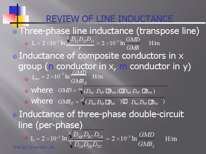
REVIEW OF LINE INDUCTANCE Three-phase line inductance (transpose line) 3 H/m Inductance of composite conductors in x group (n conductor in x, m conductor in y) D 12 D 23 D 13 GMD 7 L 2 10 ln r' GMR 7 7 Lav 2 10 ln where GMD H/m GMR X GMD mn (Daa ' Dab' � Dam )� (Dna' Dnb' � Dnm ) 2 ( Dna Dnb � GMR X n ( Daa Dab � Dan )� Dnn ) Inductance of three-phase double-circuit line (per-phase) L 2 10 ln Energy Conversion Lab 7 3 DAB DBC DCA 3 DSA DSBD SC GMD 2 10 ln GMRL 7 H/m
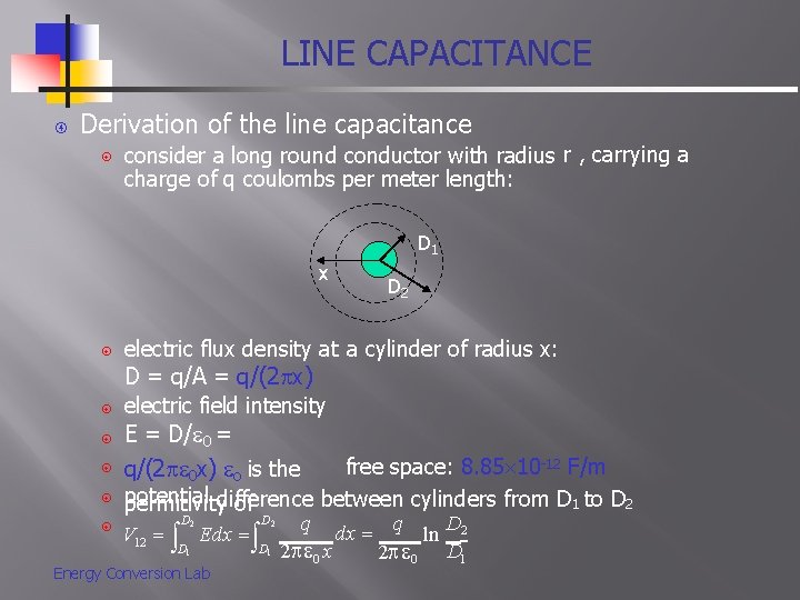
LINE CAPACITANCE Derivation of the line capacitance consider a long round conductor with radius r , carrying a charge of q coulombs per meter length: D 1 x D 2 electric flux density at a cylinder of radius x: D = q/A = q/(2 x) electric field intensity E = D/ 0 = free space: 8. 85 10 -12 F/m q/(2 0 x) o is the potential between cylinders from D 1 to D 2 permitivitydifference of D 2 D 1 V 12 Edx Energy Conversion Lab q dx q ln D 2 2 0 x 2 0 D 1
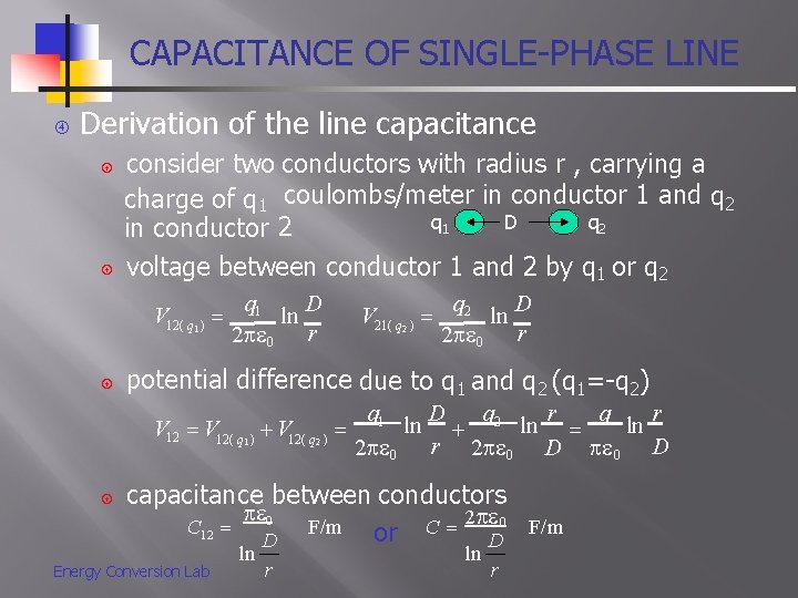
CAPACITANCE OF SINGLE-PHASE LINE Derivation of the line capacitance consider two conductors with radius r , carrying a charge of q 1 coulombs/meter in conductor 1 and q 2 q 1 D in conductor 2 voltage between conductor 1 and 2 by q 1 or q 2 V 12( q 1 ) q 1 2 0 ln D r q 2 2 0 ln D r potential difference due to q 1 and q 2 (q 1=-q 2) V 12( q 1 ) V 12( q 2 ) V 21( q 2 ) q 1 2 0 ln D q r ln 2 ln r 2 0 D capacitance between conductors 0 C 12 F/m or C 2 0 F/m D D Energy Conversion Lab ln r
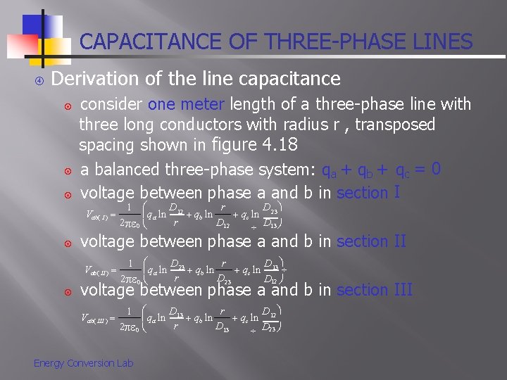
CAPACITANCE OF THREE-PHASE LINES Derivation of the line capacitance consider one meter length of a three-phase line with three long conductors with radius r , transposed spacing shown in figure 4. 18 a balanced three-phase system: qa + qb + qc = 0 voltage between phase a and b in section I Vab( I ) voltage between phase a and b in section II Vab( II ) D r 1 D qa ln 12 qb ln qc ln 23 r D 12 2 0 D 13 D r 1 D qa ln 23 qb ln qc ln 13 r D 23 2 0 D 12 voltage between phase a and b in section III Vab( III ) D r 1 D qa ln 13 qb ln qc ln 12 r D 13 2 0 D 23 Energy Conversion Lab
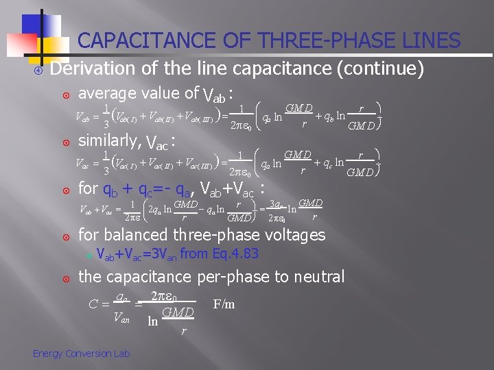
CAPACITANCE OF THREE-PHASE LINES Derivation of the line capacitance (continue) average value of Vab : Vab similarly, Vac : Vac 1 GMD 1 r qb ln Vab( I ) Vab( II ) Vab( III ) qa ln r 3 2 0 GMD 1 GMD 1 r qc ln Vac( I ) Vac( III ) qa ln r 3 2 0 GMD for qb + qc=- qa, Vab+Vac : GMD r 3 qa 1 GMD ln Vab Vac qa ln 2 qa ln r r 2 GMD 2 0 for balanced three-phase voltages Vab+Vac=3 Van from Eq. 4. 83 the capacitance per-phase to neutral C qa 2 0 Van ln GMD r Energy Conversion Lab F/m
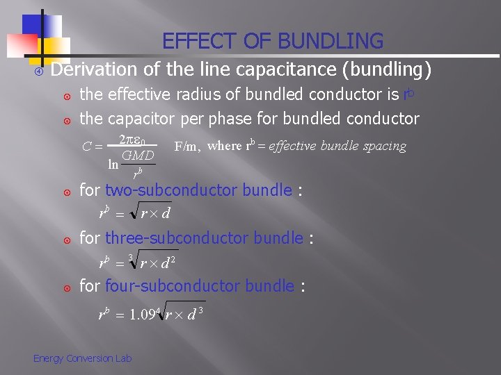
EFFECT OF BUNDLING Derivation of the line capacitance (bundling) the effective radius of bundled conductor is rb the capacitor per phase for bundled conductor C 2 0 GMD ln b r F/m, where r b effective bundle spacing for two-subconductor bundle : rb r d for three-subconductor bundle : rb 3 r d 2 for four-subconductor bundle : rb 1. 094 r d 3 Energy Conversion Lab
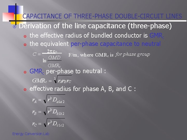
CAPACITANCE OF THREE-PHASE DOUBLE-CIRCUIT LINES Derivation of the line capacitance (three-phase) the effective radius of bundled conductor is GMRc the equivalent per-phase capacitance to neutral C ln 2 0 GMD GMRc F/m, where GMRc is for phase group GMRc per-phase to neutral : GMRc 3 r. Ar. B r. C effective radius for phase A, B, and C : r. A r b Da 1 a 2 r. B r b Db 1 b 2 r. C r b Dc 1 c 2 Energy Conversion Lab
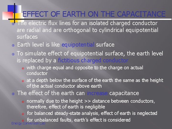
EFFECT OF EARTH ON THE CAPACITANCE The electric flux lines for an isolated charged conductor are radial and are orthogonal to cylindrical equipotential surfaces Earth level is like equipotential surface To simulate effect of equipotential surface, the earth level is replaced by a fictitious charged conductor with charge equal and opposite to the charge on actual conductor at a depth below the surface of the earth the same as the height of the actual conductor above earth The effect of the earth can increase capacitance normally due to the height >> distance between conductors, therefore, effect of earth is negligible for balanced steady-state analysis, effect of earth is neglected for unbalanced faults, earth’s effect is considered Energy Conversion Lab
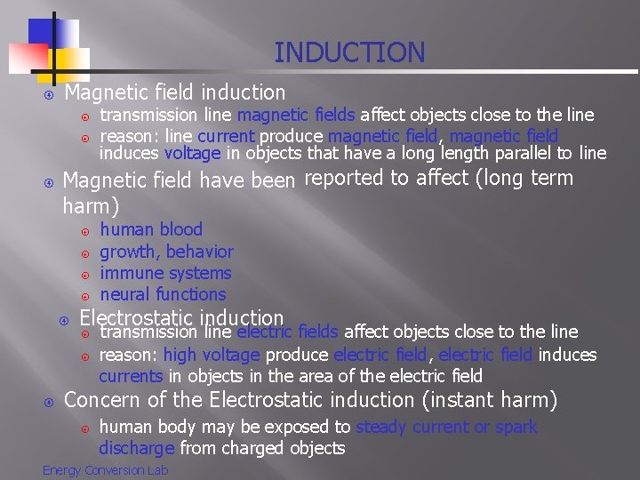
INDUCTION Magnetic field induction Magnetic field have been reported to affect (long term harm) human blood growth, behavior immune systems neural functions Electrostatic induction transmission line magnetic fields affect objects close to the line reason: line current produce magnetic field, magnetic field induces voltage in objects that have a long length parallel to line transmission line electric fields affect objects close to the line reason: high voltage produce electric field, electric field induces currents in objects in the area of the electric field Concern of the Electrostatic induction (instant harm) human body may be exposed to steady current or spark discharge from charged objects Energy Conversion Lab
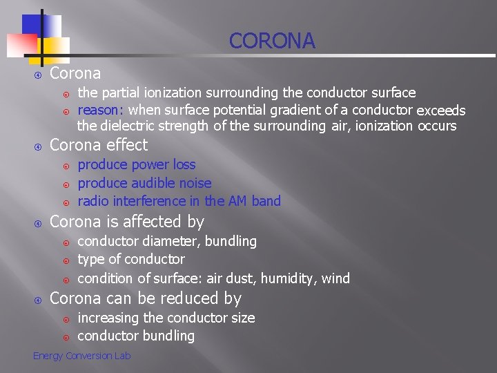
CORONA Corona effect produce power loss produce audible noise radio interference in the AM band Corona is affected by the partial ionization surrounding the conductor surface reason: when surface potential gradient of a conductor exceeds the dielectric strength of the surrounding air, ionization occurs conductor diameter, bundling type of conductor condition of surface: air dust, humidity, wind Corona can be reduced by increasing the conductor size conductor bundling Energy Conversion Lab
UNIT 3 MODELLING AND PERFORMANCE OF TRANSMISSION LINES 1
Introductio n Analyze the performance of single phase and balanced three-phase transmission lines under normal steady-state operating conditions. Expression of voltage and current at any point along the line are developed, where the nature of the series impedance and shunt admittance is taken into account. The performance of transmission line is measured based on the voltage regulation and line loadability. 2
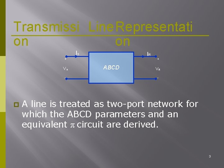
Transmissi Line. Representati on on Is IR + Vs - ABCD + VR - A line is treated as two-port network for which the ABCD parameters and an equivalent π circuit are derived. 3
Transmission Line Representation To facilitate the performance calculations relating to a transmission line, the line is approximated as a series–parallel interconnection of the relevant parameters. Consider a transmission line to have: A sending end a receiving end; A series resistance and inductance; and A shunt capacitance and conductance 4
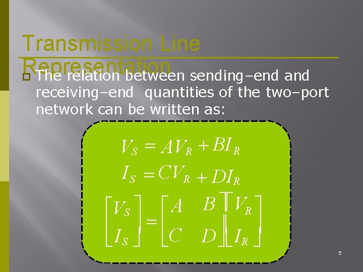
Transmission Line Representation The relation between sending–end and receiving–end quantities of the two–port network can be written as: VS AVR BI R I S CVR DIR VS A B VR I S C D I R 5
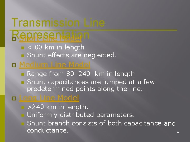
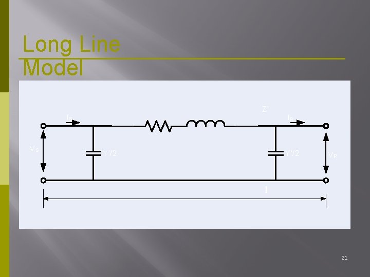
Transmission Line Representation Short Line Model Medium Line Model < 80 km in length Shunt effects are neglected. Range from 80– 240 km in length Shunt capacitances are lumped at a few predetermined points along the line. Long Line Model >240 km in length. Uniformly distributed parameters. Shunt branch consists of both capacitance and conductance. 6
Shor Line. Mode t l IS Z R XL IR VR VS l 7
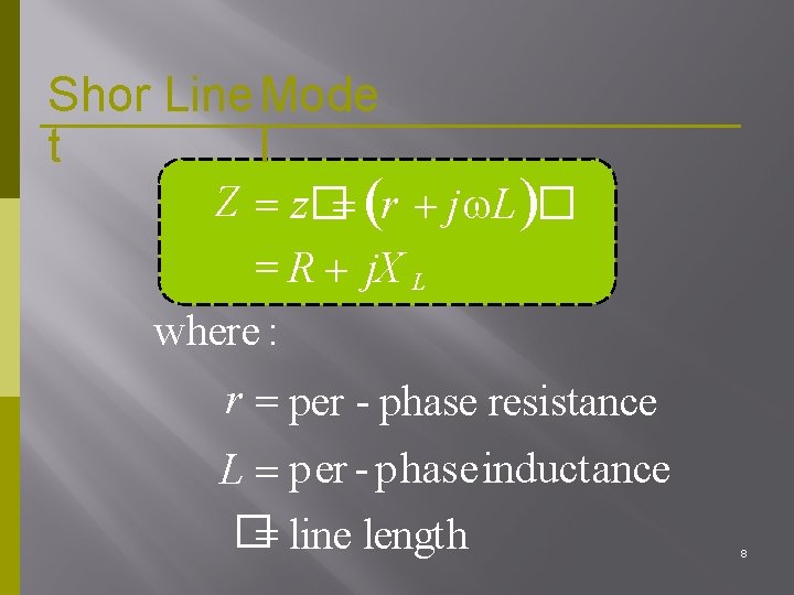
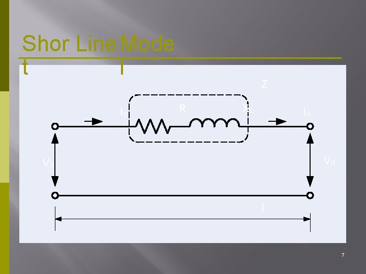
Shor Line. Mode t l Z z� r j L � R j. X L where : r per - phase resistance L per - phaseinductance � line length 8
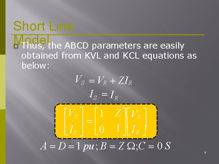
Short Line Model Thus, the ABCD parameters are easily obtained from KVL and KCL equations as below: VS VR ZIR IS IR VS 1 Z VR I S 0 1 I R A D 1 pu ; B Z ; C 0 S 9
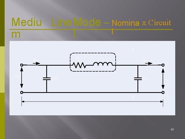
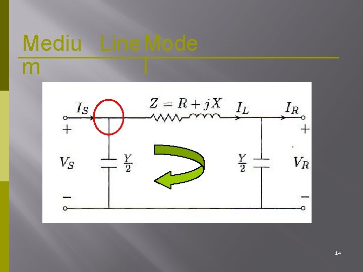
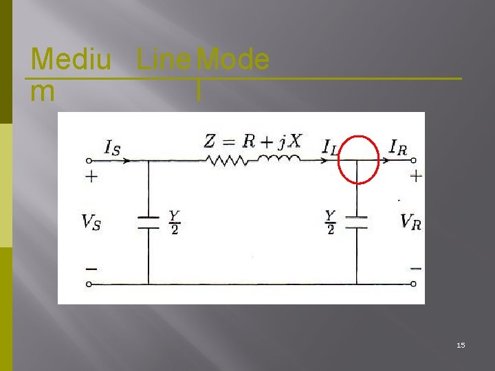
Mediu Line. Mode – Nomina π Circuit l m l Z R IS VS XL IR Y/2 VR l 10
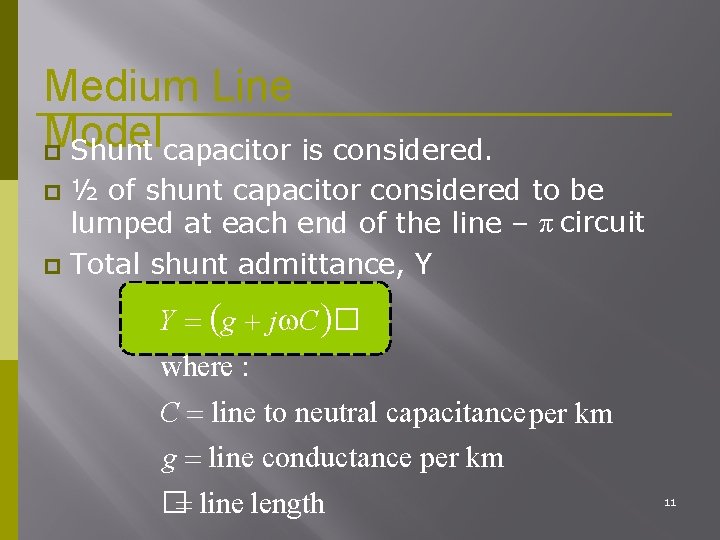
Medium Line Model Shunt capacitor is considered. ½ of shunt capacitor considered to be lumped at each end of the line – π circuit Total shunt admittance, Y Y g j C � where : C line to neutral capacitance per km g line conductance per km � line length 11
Medium Line Model Under normal condition, shunt conductance per unit length (the leakage current) over the insulators and due to corona is negligible Thus, g = 0 12
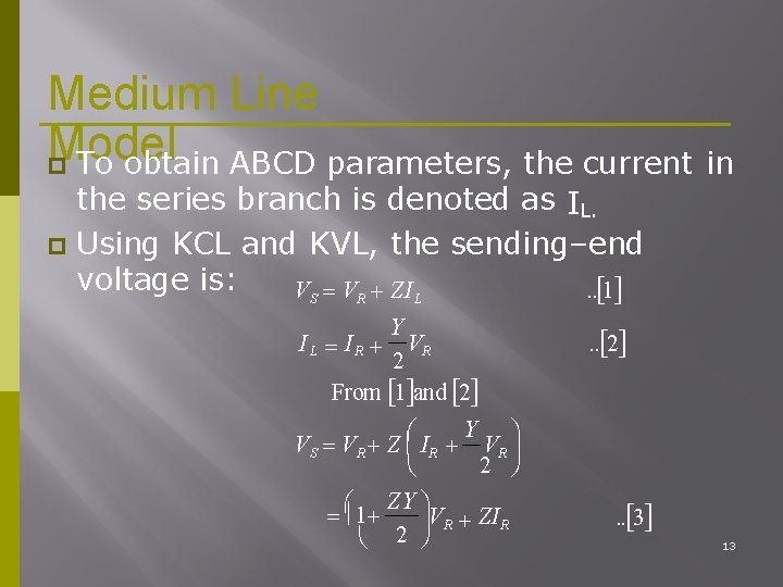
Medium Line Model To obtain ABCD parameters, the current in the series branch is denoted as IL. Using KCL and KVL, the sending–end voltage is: . . 1 VS VR ZI L Y VR 2 From 1 and 2 IL IR Y VR VS VR Z IR 2 ZY 1 VR ZIR 2 . . 2 . . 3 13
Mediu Line. Mode m l 14
Mediu Line. Mode m l 15
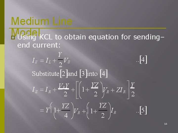
Medium Line Model Using KCL to obtain equation for sending– end current: Y I S I L VS 2 Substitute 2 and 3 into 4 . . 4 Y YZ V RY IS IR 1 VR ZI R 2 2 2 YZ YZ Y 1 I R. . 5 VR 1 2 4 16
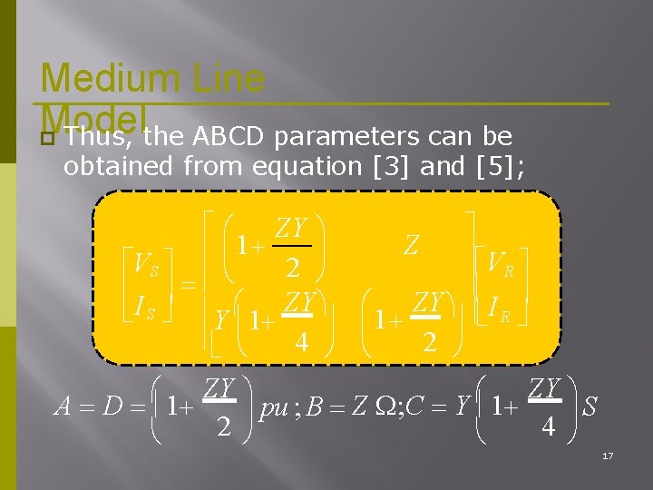
Medium Line Model Thus, the ABCD parameters can be obtained from equation [3] and [5]; ZY 1 Z VR VS 2 I S Y 1 ZY I R 4 2 ZY ZY A D 1 pu ; B Z ; C Y 1 S 2 4 17
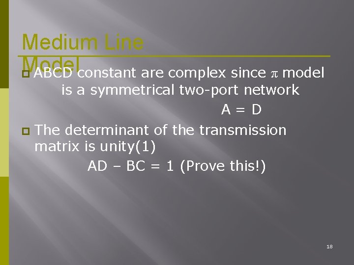
Medium Line Model ABCD constant are complex since π model is a symmetrical two-port network A=D The determinant of the transmission matrix is unity(1) AD – BC = 1 (Prove this!) 18
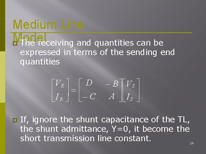
Medium Line Model The receiving and quantities can be expressed in terms of the sending end quantities V R D C I R B V S A I S If, ignore the shunt capacitance of the TL, the shunt admittance, Y=0, it become the short transmission line constant. 19
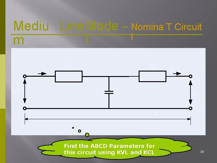
Mediu Line. Mode – Nomina T Circuit l m l Z/2 IS VS Y IR VR l Find the ABCD Parameters for this circuit using KVL and KCL 20
Long Line Model Z’ IS VS Y’/2 IR Y’/2 VR l 21
Long Line Model The shunt capacitance and series impedance must be treated as distributed quantities The ‘V’ and ‘I’ on the line must be found by solving the differential equation of the transmission line. 22
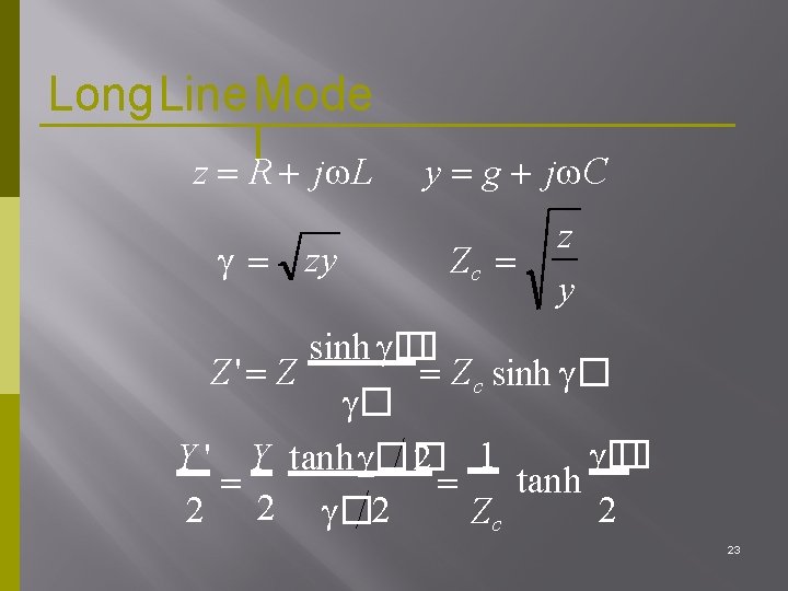
Long. Line. Mode l z R j L zy y g j C Zc z y sinh � � Z' Z Z c sinh � � Y ' Y t anh �� 2 1 tanh 2 2 � 2 2 Zc 23
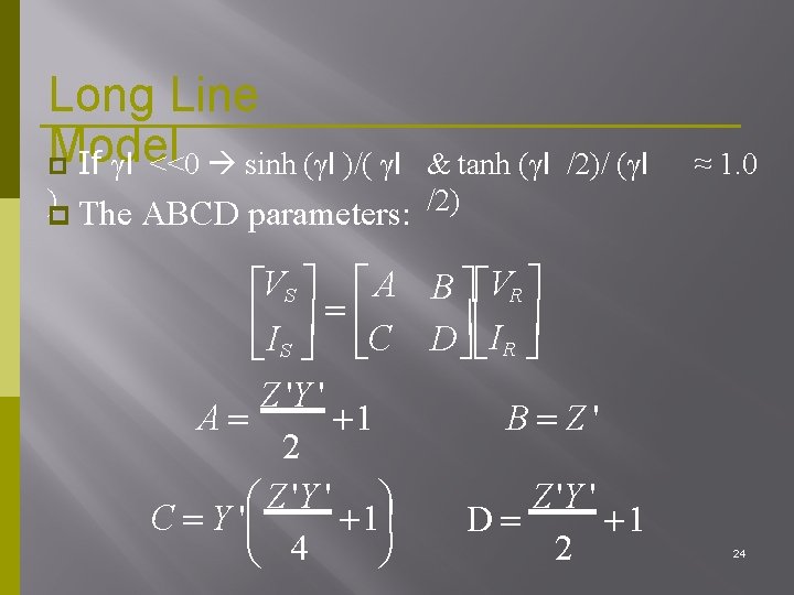
Long Line Model If γl <<0 sinh (γl )/( γl & tanh (γl /2)/ (γl ) The ABCD parameters: /2) VS A B VR I S C D I R Z 'Y ' A 1 B Z' 2 Z 'Y ' C Y ' 1 D 1 2 4 ≈ 1. 0 24
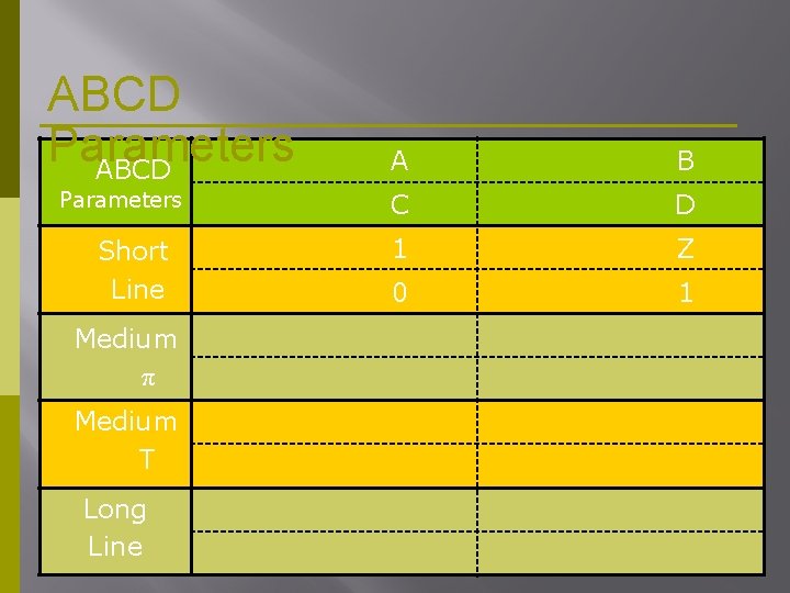
ABCD Parameters Short Line A B C D 1 Z 0 1 Medium π Medium T Long Line 25
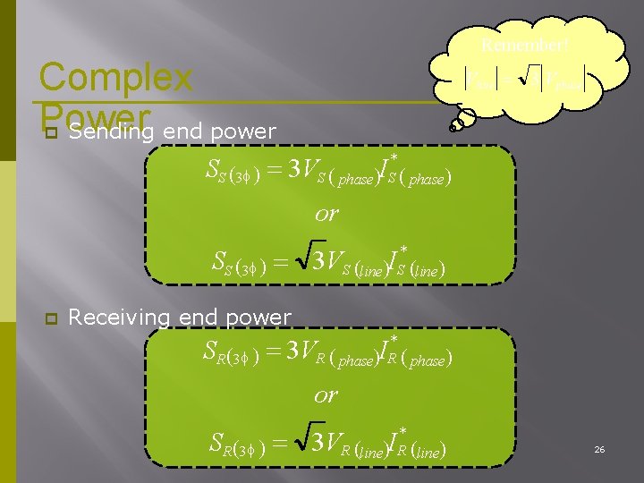
Remember! Complex Power Sending end power Vline 3 Vphase SS 3 3 V * S phase I or SS 3 3 V * S line I Receiving end power SR 3 3 V * R phase I or * SR 3 3 VR line IR line 26
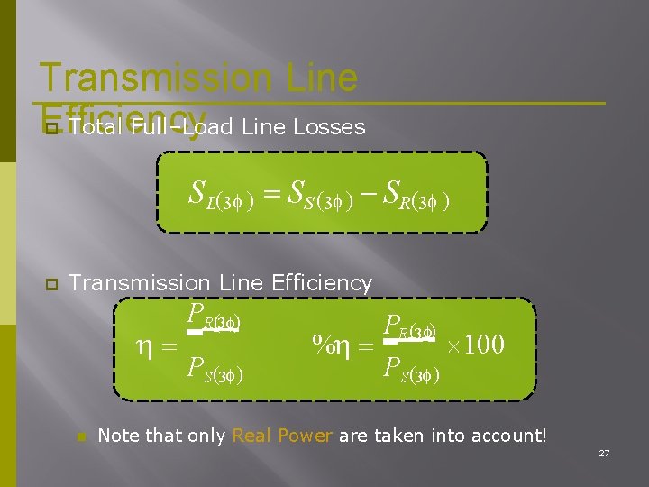
Transmission Line Efficiency Total Full–Load Line Losses SL 3 SS 3 SR 3 Transmission Line Efficiency PR 3 PS 3 % PR 3 PS 3 100 Note that only Real Power are taken into account! 27
Voltage Regulation ABCD parameters can be used to describe the variation of line voltage with line loading. Voltage regulation is the change in voltage at the receiving end of the line when the load varies from no–load to a specified full–load at a specified power factor, while the sending end is held constant. 28
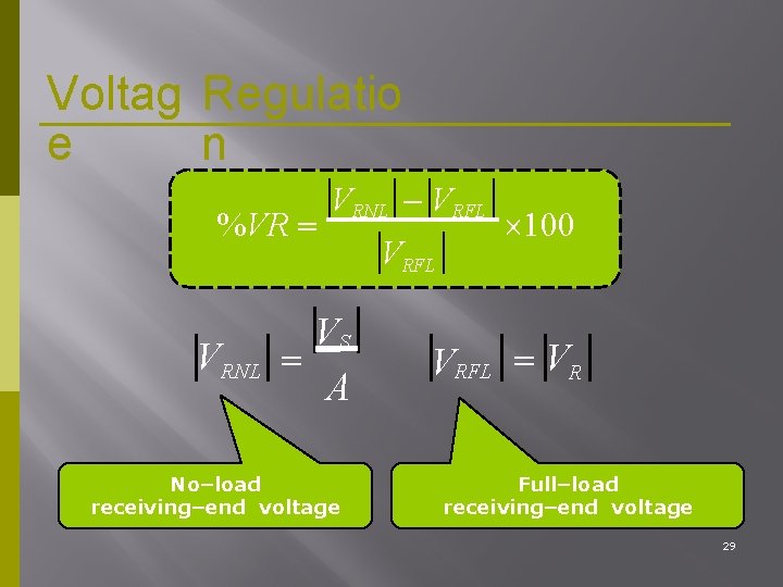
Voltag Regulatio e n %VR VRNL VRFL VS A No–load receiving–end voltage VRFL 100 VRFL VR Full–load receiving–end voltage 29
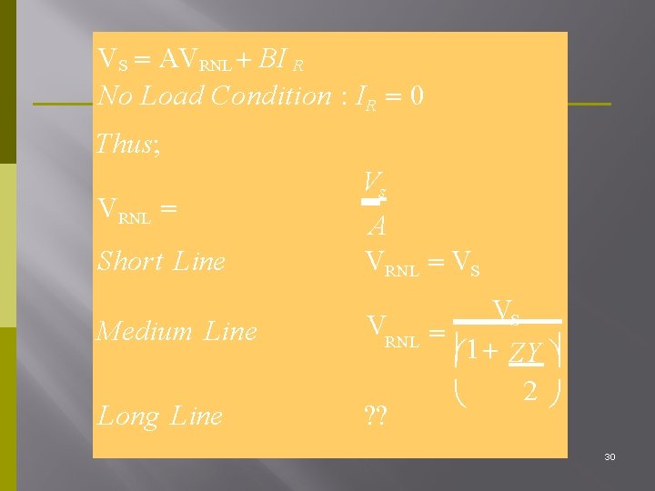
VS AVRNL BI R No Load Condition : IR 0 Thus; VRNL Short Line Vs A VRNL VS Medium Line VRNL Long Line ? ? VS 1 ZY 2 30
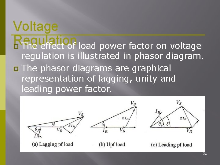
Voltage Regulation The effect of load power factor on voltage regulation is illustrated in phasor diagram. The phasor diagrams are graphical representation of lagging, unity and leading power factor. 31
Voltage Regulation The higher (worse) voltage regulation occurs for the lagging pf load where VRNL exceeds VRFL by the larger amount. A smaller or even negative voltage regulation occurs in leading pf load. 32
Voltage Regulation In practice, transmission line voltages decrease when heavily loaded and increase when lightly loaded. EHV lines are maintained within ± 5% of rated voltage, corresponding to about 10% voltage regulation for lower voltage lines also considered good operating practice. 33
Line Loadability Another important issue that affect transmission line performance. 3 major line loading limits are: Thermal limit Voltage drop limit Short transmission lines [<80 km length] Longer line length [ 80– 300 km length] Steady-state stability limit Line length over 300 km 34
Exampl e A 220 -k. V, three-phase transmission line is 40 km long. The resistance per phase is 0. 15 Ω/km and the inductance per phase is 1. 5915 m. H/km. The shunt capacitance is negligible. Use the line model to find the voltage and power at the sending end and the voltage regulation and efficiency when the line is supplying a three-phase load of a) 381 MVA at 0. 8 pf lagging at 220 k. V b) 381 MVA at 0. 8 pf leading at 220 k. V 35
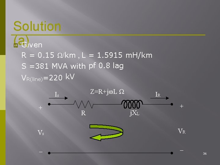
Solution (a) Given R = 0. 15 Ω/km , L = 1. 5915 m. H/km S =381 MVA with pf 0. 8 lag VR(line)=220 k. V Z=R+jωL Ω Is + R IR j. XL + Vs VR _ _ 36
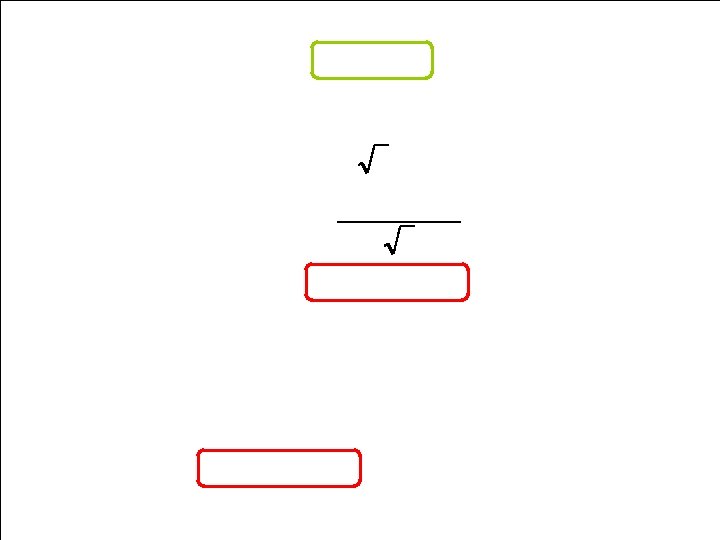
Find sending end voltage, VS VR ZIR Therefore, find VR , Z, and IR V R phase VR Lin e 3 220 0 o k. V 3 127 0 o k. V The series impedance per phase; Z 40 km r j L l 0. 15 j 2 50 1. 5915 m 40 6 j 20 37
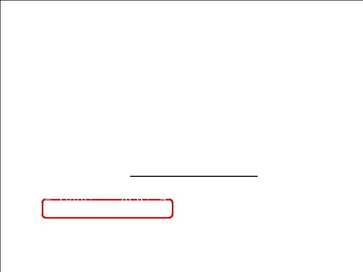
S 381 M VA, cos - 1 0. 8 36. 87 o S R Thus, 3 8 1 3 6. 87 o M V A 3 0 4. 8 M W j 2 2 8. 6 M v ar S R 3 V R ( P h a s e ) I *R IR SR 3 V R ( P h a s e ) S* R 3 8 1 3 6. 8 7 o M V A 3 V 3 1 2 7 0 o k V 1000 36. 87 o A * (Phase) R 38
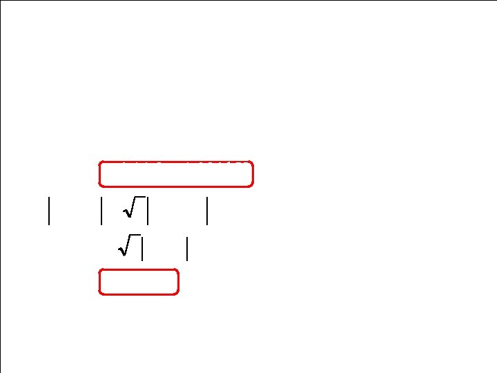
Therefore, VS(Phase) VR Phase ZIR 127 0 o k. V 6 j 20 1000 36. 87 o A 144. 3 4. 93 o k. V VS Line 3 VS Phase 3 144. 3 250 V 39

Find Sending - end Power, SS 3 VS Line IS I S I R 1 0 0 0 3 6. 8 7 o A S S 3 V R ( P h a s e ) I *R 3 1 4 4. 3 3 4. 9 3 o V 1 0 0 0 3 6. 8 7 o A 322. 8 MW j 288. 6 M var 433 41. 8 o MVA 40
Voltage Regulation, V RN L V RFL %VR 100 VRFL 2 5 0 2 2 0 1 0 0 220 13. 6% Effiency, η % PR 304. 8 100 PS 322. 8 100 94. 4% 41

INSULATORS AND CABLES
Insulators: • • An insulator, also called a dielectric, is a material that resists the flow of electric current. An insulating material has atoms with tightly bonded valence electrons. These materials are used in parts of electrical equipment, also called insulators or insulation, intended to support or separate electrical conductors without passing current through themselves. The term is often used more specifically to refer to insulating supports that attach electric power transmission wires to utility poles or pylons. Some materials such as glass or Teflon are very good electrical insulators. A much larger class of materials, for example rubber-like polymers and most plastics are still "good enough" to insulate electrical wiring and cables even though they may have lower bulk resistivity. These materials can serve as practical and safe insulators for low to moderate voltages (hundreds, or even thousands, of volts).
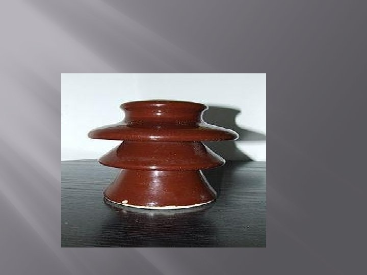
Insulators: • Insulators are used for high-voltage power transmission are made from glass, porcelain, or composite polymer materials. Porcelain insulators are made from clay, quartz or alumina and feldspar, and are covered with a smooth glaze to shed dirt. Insulators made from porcelain rich in alumina are used where high • mechanical strength is a criterion. Porcelain has a dielectric strength of about 4 -10 k. V/mm. Glass has a higher dielectric strength, but it attracts condensation and the thick irregular shapes needed for insulators are difficult to cast without internal strains. Some insulator manufacturers stopped making glass insulators in the late 1960 s, switching to ceramic materials.
Insulators: • Recently, some electric utilities have begun converting to polymer composite materials for some types of insulators. These are typically composed of a central rod made of fibre reinforced plastic and an outer weathershed • made of silicone rubber or EPDM. Composite insulators are less costly, lighter in weight, and have excellent hydrophobic capability. This combination makes them ideal for service in polluted areas. However, these materials do not yet have the long-term proven service life of glass and porcelain.
Insulators: • Design • Cap and pin insulator string (the vertical string of discs) on a 275 k. V suspension pylon. The electrical breakdown of an insulator due to excessive voltage can occur in one of two ways: Puncture voltage is the voltage across the insulator(when installed in its normal manner) which causes a breakdown and conduction through the interior of the insulator. The heat resulting from the puncture arc usually damages the insulator irreparably. Flashover voltage is the voltage which causes the air around or along the surface of the insulator to break down and conduct, causing a 'flashover' arc along the outside of the insulator. They are usually designed to withstand this without damage. High voltage insulators are designed with a lower flashover voltage than puncture voltage, so they will flashover before they puncture, to avoid damage. •
Insulators: • • Dirt, pollution, salt, and particularly water on the surface of a high voltage insulator can create a conductive path across it, causing leakage currents and flashovers. The flashover voltage can be more than 50% lower when the insulator is wet. High voltage insulators for outdoor use are shaped to maximise the length of the leakage path along the surface from one end to the other, called the creepage length, to minimize these leakage currents. To accomplish this the surface is molded into a series of corrugations or concentric disk shapes. These usually include one or more sheds; downward facing cup-shaped surfaces that act as umbrellas to ensure that the part of the surface leakage path under the 'cup' stays dry in wet weather. Minimum creepage distances are 20 -25 mm/k. V, but must be increased in high pollution or airborne sea-salt areas.
Cables • A cable is one or more strands bound together. Electrical cables may contain one or more metal conductors, which may be individually insulated or covered. An optical cable contains one or more optical fibers in a protective jacket that supports the fibers. Mechanical cables such as wire rope may contain a large number of metal or fiber strands.
Cables • Electrical cables may be made flexible by stranding the wires. The technical issue is to reduce the skin effect voltage drop while using with alternating currents. In this process, smaller individual wires are twisted or braided together to produce larger wires that are more flexible than solid wires of similar size. Bunching small wires • before concentric stranding adds the most flexibility. A thin coat of a specific material (usually tin-which improved striping of rubber, or for low friction of moving conductors, but it could be silver, gold another materials and of course the wire can be bare - with no coating material) on the individual wires. Tight lays during stranding makes the cable extensible (CBA - as in telephone handset cords).
Cables • Bundling the conductors and eliminating multi-layers ensures a uniform bend radius across each conductor. Pulling and compressing forces balance one another around the high-tensile center cord that provides the necessary inner stability. As a result the cable core remains stable even under maximum bending stress. • Cables can be securely fastened and organized, such as using cable trees with the aid of cable ties or cable lacing. Continuous-flex or flexible cables used in moving applications within cable carriers can be secured using strain relief devices or cable ties. Copper corrodes easily and so should be layered with Lacquer.
SUBSTATION, GROUNDING SYSTEM AND DISTRIBUTION SYSTEM
PARTS OF A SUBSTATION Parts of a substation can be grouped into several categories: (a) (b) (c) (d) Site Related Facilities Bus & Equipment "Outdoor" Relay, Control, Metering, and Communications Control House In general, in substations there is a site on which is located the major cir cuit bus and equipment as well as a contr ol house. The control house contains protection, control, metering, and communication equipment as well as equipment related to the ancillary power systems (station service, 125 vdc, etc. )
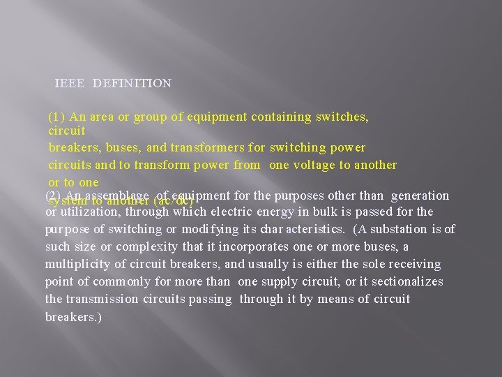
IEEE DEFINITION (1) An area or group of equipment containing switches, circuit breakers, buses, and transformers for switching power circuits and to transform power from one voltage to another or to one (2) An assemblage of equipment for the purposes other than generation system to another (ac/dc) or utilization, through which electric energy in bulk is passed for the pur pose of switching or modifying its char acter istics. (A substation is of such size or complexity that it incorporates one or more buses, a multiplicity of circuit breakers, and usually is either the sole receiving point of commonly for more than one supply circuit, or it sectionalizes the transmission circuits passing through it by means of circuit breakers. )

- Slides: 120