
EE 330 Lecture 28 SmallSignal Model Extension Applications
- Slides: 42
EE 330 Lecture 28 Small-Signal Model Extension Applications of the Small-signal Model
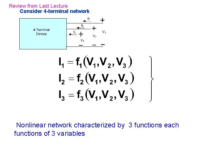
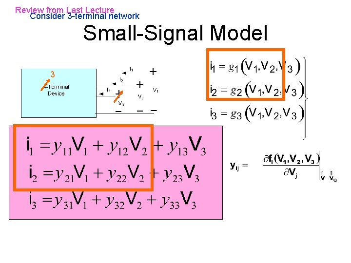
Review from Last Lecture Consider 4 -terminal network Nonlinear network characterized by 3 functions each functions of 3 variables
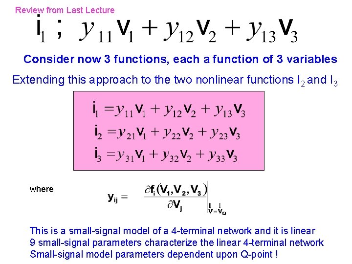
Review from Last Lecture Consider now 3 functions, each a function of 3 variables Extending this approach to the two nonlinear functions I 2 and I 3 where This is a small-signal model of a 4 -terminal network and it is linear 9 small-signal parameters characterize the linear 4 -terminal network Small-signal model parameters dependent upon Q-point !
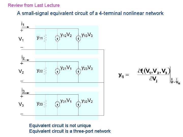
Review from Last Lecture A small-signal equivalent circuit of a 4 -terminal nonlinear network Equivalent circuit is not unique Equivalent circuit is a three-port network
Review from Last Lecture Consider 3 -terminal network Small-Signal Model 3
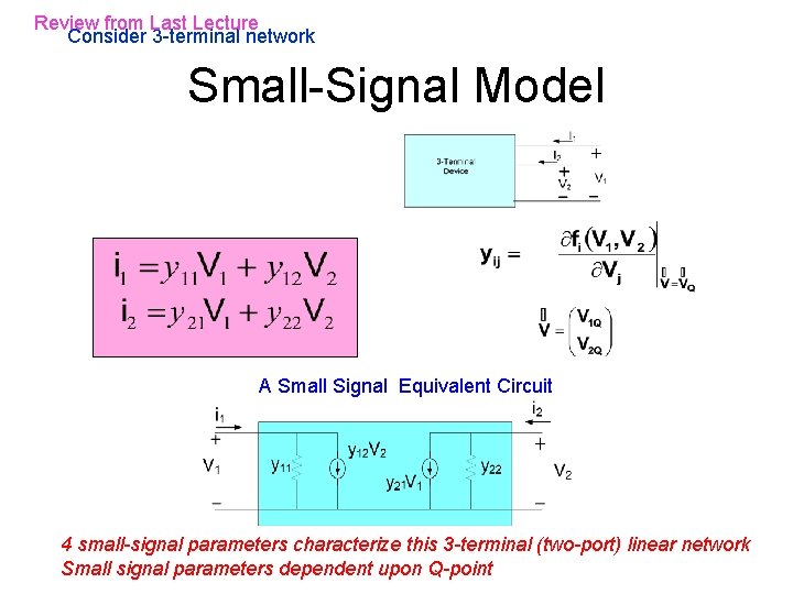
Review from Last Lecture Consider 3 -terminal network Small-Signal Model A Small Signal Equivalent Circuit 4 small-signal parameters characterize this 3 -terminal (two-port) linear network Small signal parameters dependent upon Q-point
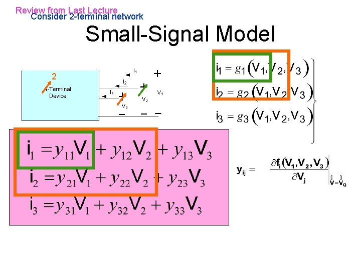
Review from Last Lecture Consider 2 -terminal network Small-Signal Model 2
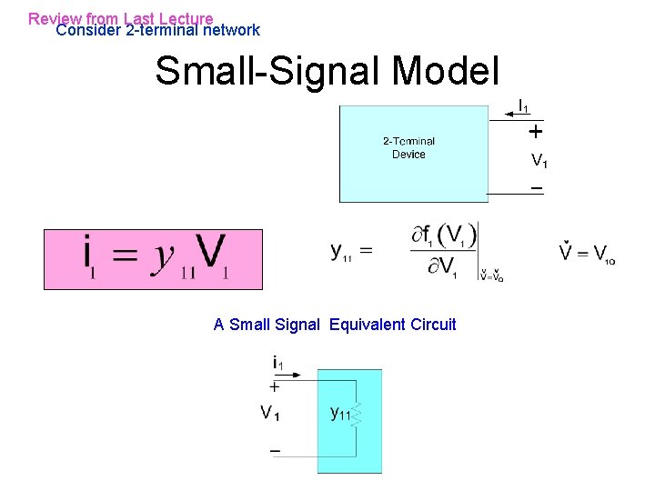
Review from Last Lecture Consider 2 -terminal network Small-Signal Model A Small Signal Equivalent Circuit
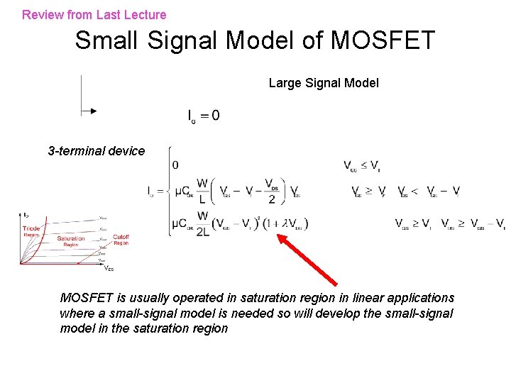
Review from Last Lecture Small Signal Model of MOSFET Large Signal Model 3 -terminal device MOSFET is usually operated in saturation region in linear applications where a small-signal model is needed so will develop the small-signal model in the saturation region
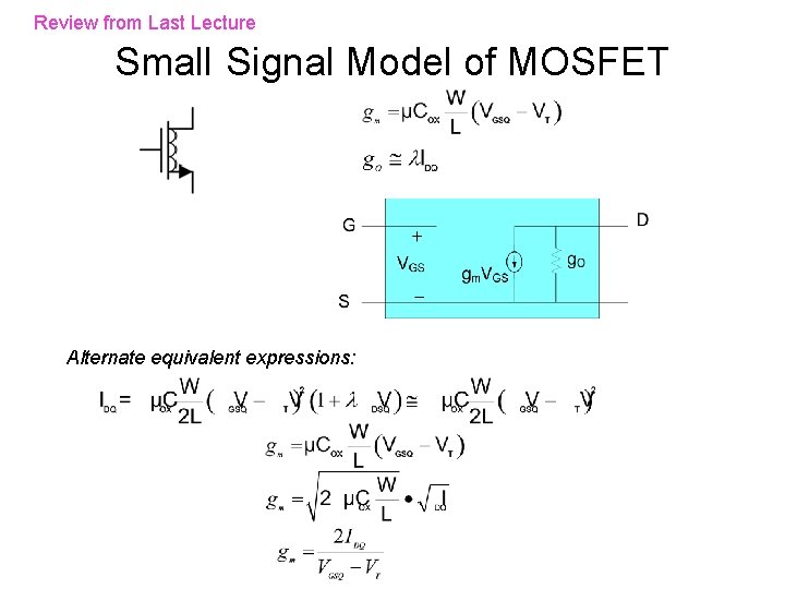
Review from Last Lecture Small Signal Model of MOSFET Alternate equivalent expressions:
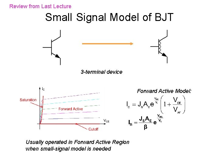
Review from Last Lecture Small Signal Model of BJT 3 -terminal device Forward Active Model: Usually operated in Forward Active Region when small-signal model is needed
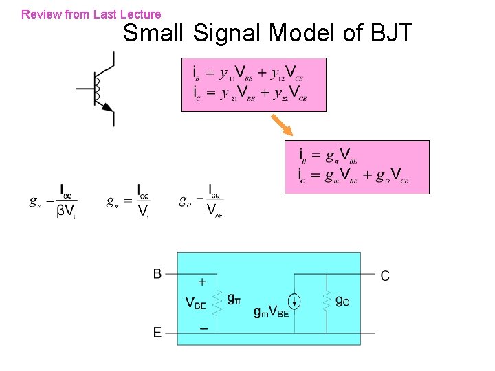
Review from Last Lecture Small Signal Model of BJT
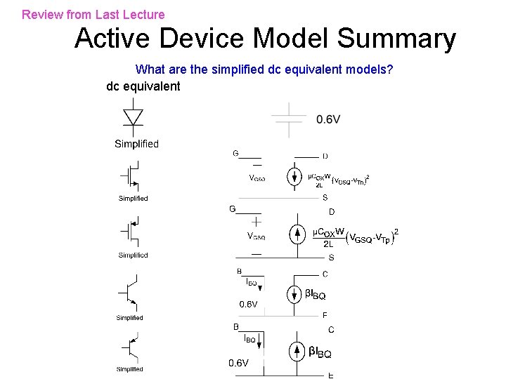
Review from Last Lecture Active Device Model Summary What are the simplified dc equivalent models?
Review from Last Lecture Active Device Model Summary What are the simplified dc equivalent models? dc equivalent
Recall: Alternative Approach to small-signal analysis of nonlinear networks 1. Linearize nonlinear devices (have small-signal model for key devices!) 2. Replace all devices with small-signal equivalent 3. Solve linear small-signal network Remember that the small-signal model is operating point dependent! Thus need Q-point to obtain values for small signal parameters
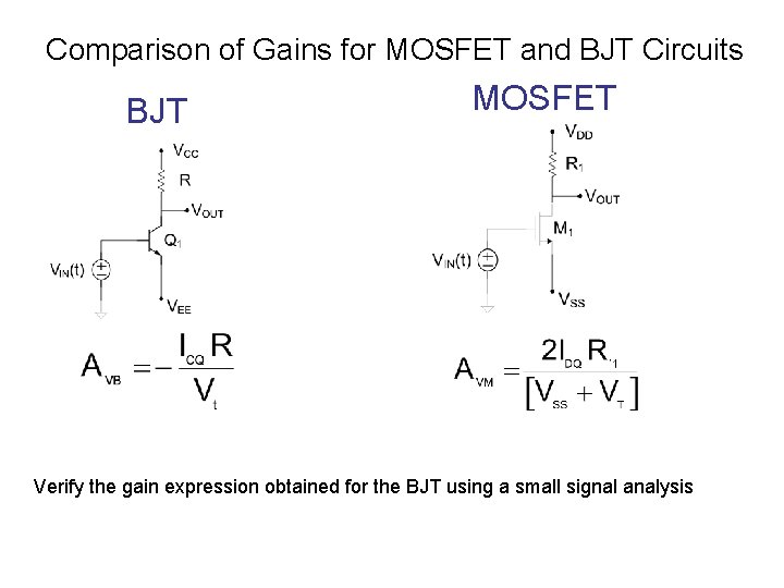
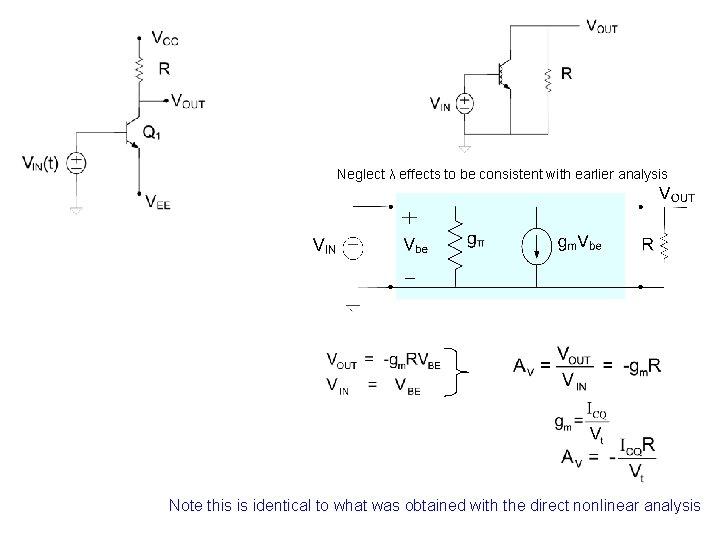
Comparison of Gains for MOSFET and BJT Circuits BJT MOSFET Verify the gain expression obtained for the BJT using a small signal analysis
Neglect λ effects to be consistent with earlier analysis Note this is identical to what was obtained with the direct nonlinear analysis
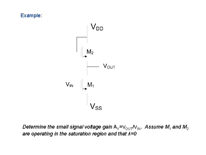
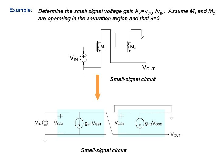
Example: Determine the small signal voltage gain AV=VOUT/VIN. Assume M 1 and M 2 are operating in the saturation region and that λ=0
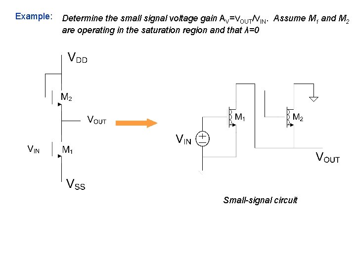
Example: Determine the small signal voltage gain AV=VOUT/VIN. Assume M 1 and M 2 are operating in the saturation region and that λ=0 Small-signal circuit
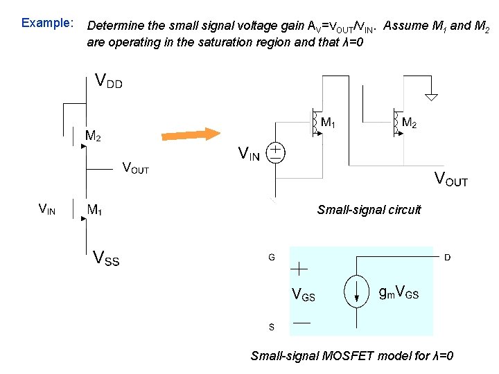
Example: Determine the small signal voltage gain AV=VOUT/VIN. Assume M 1 and M 2 are operating in the saturation region and that λ=0 Small-signal circuit Small-signal MOSFET model for λ=0
Example: Determine the small signal voltage gain AV=VOUT/VIN. Assume M 1 and M 2 are operating in the saturation region and that λ=0 Small-signal circuit
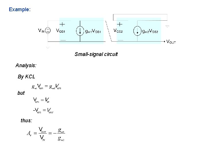
Example: Small-signal circuit Analysis: By KCL but thus:
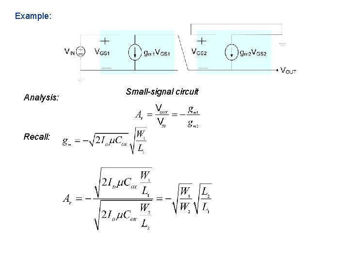
Example: Analysis: Recall: Small-signal circuit
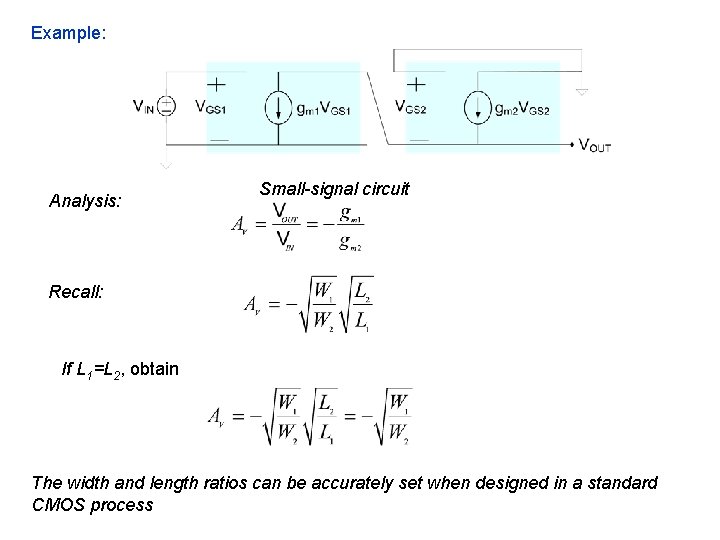
Example: Analysis: Small-signal circuit Recall: If L 1=L 2, obtain The width and length ratios can be accurately set when designed in a standard CMOS process
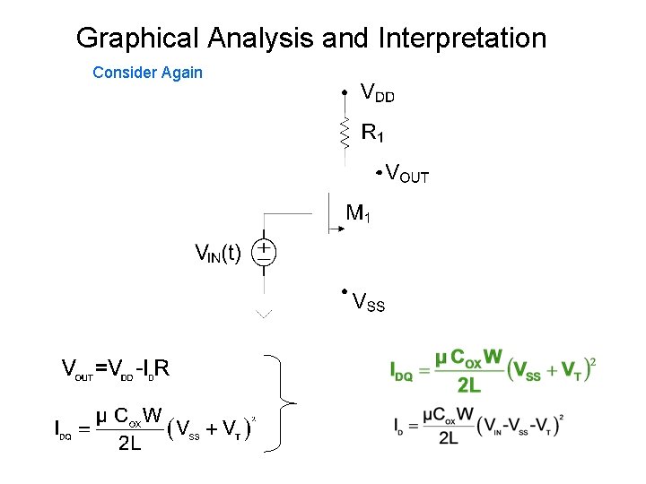
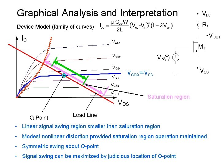
Graphical Analysis and Interpretation Consider Again
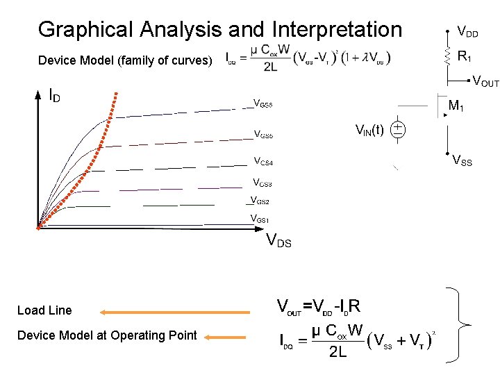
Graphical Analysis and Interpretation Device Model (family of curves) Load Line Device Model at Operating Point
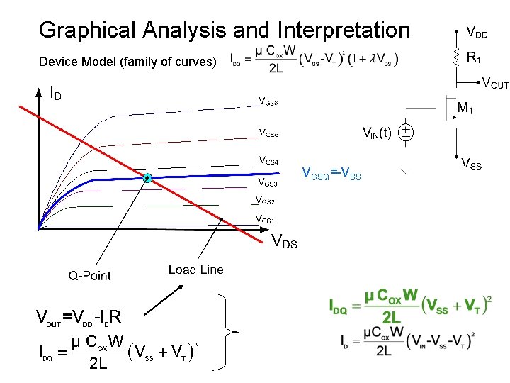
Graphical Analysis and Interpretation Device Model (family of curves) VGSQ=-VSS
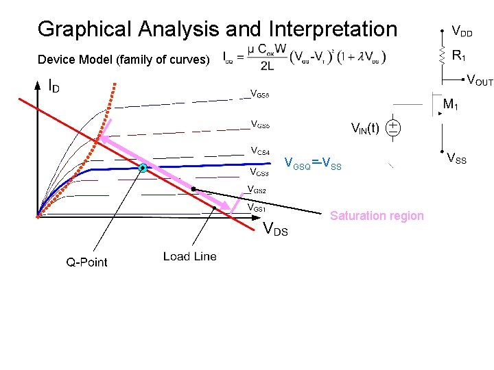
Graphical Analysis and Interpretation Device Model (family of curves) VGSQ=-VSS Saturation region
Graphical Analysis and Interpretation Device Model (family of curves) VGSQ=-VSS Saturation region • Linear signal swing region smaller than saturation region • Modest nonlinear distortion provided saturation region operation maintained • Symmetric swing about Q-point • Signal swing can be maximized by judicious location of Q-point
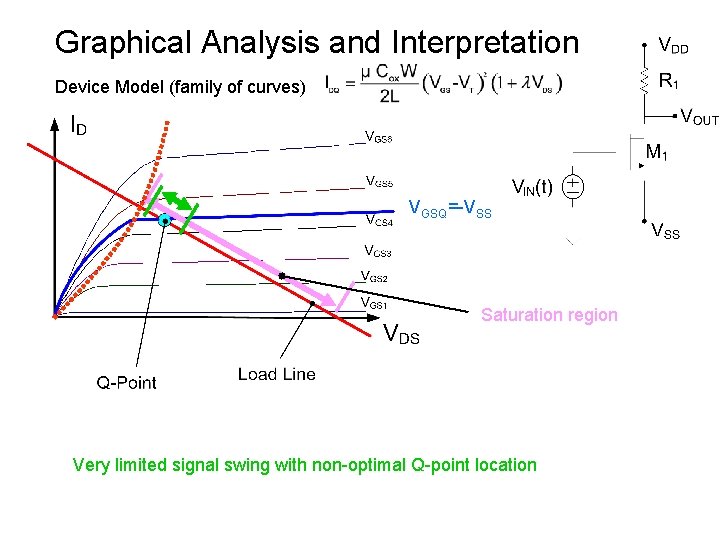
Graphical Analysis and Interpretation Device Model (family of curves) VGSQ=-VSS Saturation region Very limited signal swing with non-optimal Q-point location
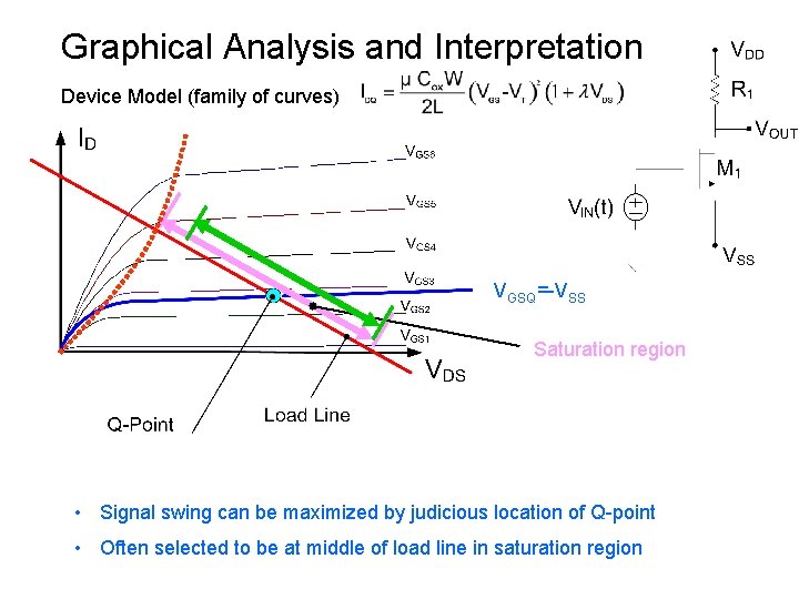
Graphical Analysis and Interpretation Device Model (family of curves) VGSQ=-VSS Saturation region • Signal swing can be maximized by judicious location of Q-point • Often selected to be at middle of load line in saturation region
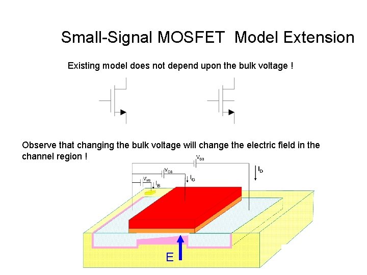
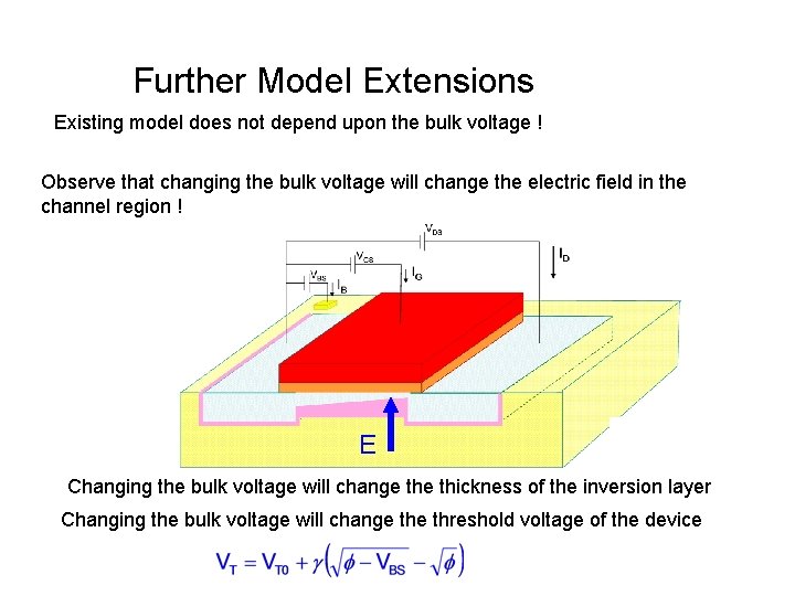
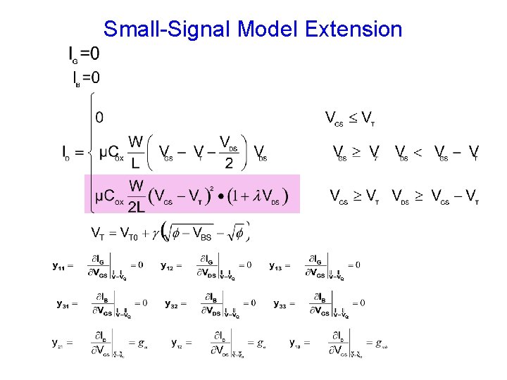
Small-Signal MOSFET Model Extension Existing model does not depend upon the bulk voltage ! Observe that changing the bulk voltage will change the electric field in the channel region ! E
Further Model Extensions Existing model does not depend upon the bulk voltage ! Observe that changing the bulk voltage will change the electric field in the channel region ! E Changing the bulk voltage will change thickness of the inversion layer Changing the bulk voltage will change threshold voltage of the device
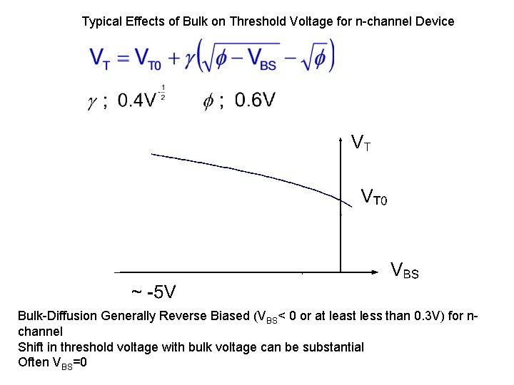
Typical Effects of Bulk on Threshold Voltage for n-channel Device Bulk-Diffusion Generally Reverse Biased (VBS< 0 or at least less than 0. 3 V) for nchannel Shift in threshold voltage with bulk voltage can be substantial Often VBS=0
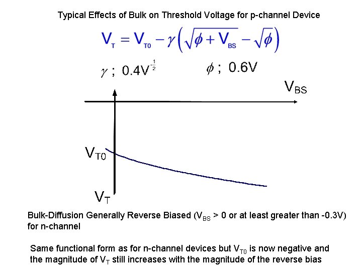
Typical Effects of Bulk on Threshold Voltage for p-channel Device Bulk-Diffusion Generally Reverse Biased (VBS > 0 or at least greater than -0. 3 V) for n-channel Same functional form as for n-channel devices but VT 0 is now negative and the magnitude of VT still increases with the magnitude of the reverse bias
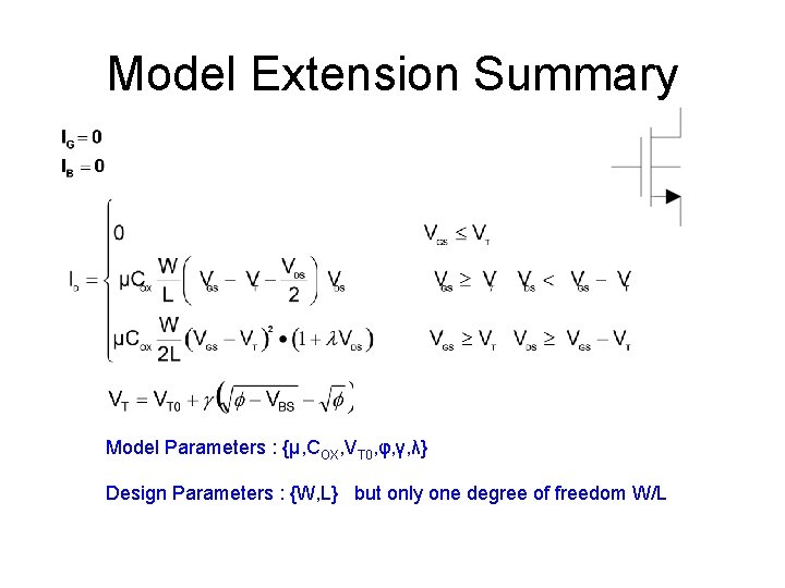
Model Extension Summary Model Parameters : {μ, COX, VT 0, φ, γ, λ} Design Parameters : {W, L} but only one degree of freedom W/L
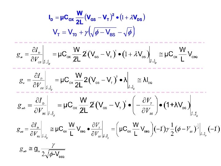
Small-Signal Model Extension
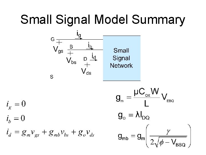
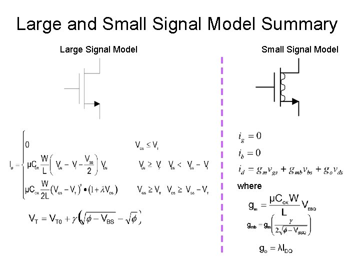
Small Signal Model Summary
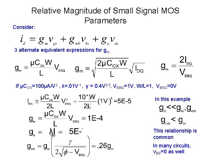
Relative Magnitude of Small Signal MOS Parameters Consider: 3 alternate equivalent expressions for gm If μCOX=100μA/V 2 , λ=. 01 V-1, γ = 0. 4 V 0. 5, VEBQ=1 V, W/L=1, VBSQ=0 V In this example This relationship is common In many circuits, VBS=0 as well
Large and Small Signal Model Summary Large Signal Model Small Signal Model where
End of Lecture 28