
EE 216 Electrical Engineering Dr Unnikrishnan P C




- Slides: 49
EE 216 Electrical Engineering Dr. Unnikrishnan P. C. Professor, EEE
Dr. Unnikrishnan P. C. l l l BTech. : EEE, NSS College of Engineering, 1981 -85. MTech: Control & Instrumentation, IIT Bombay, 1990 -92. Ph. D. : EEE, Karpagam University, Coimbatore, 2010 -2016.
Dr. Unnikrishnan P. C. l l l 1986 -1996 : Assistant Professor and Associate Professor, Rajasthan Technical University, Kota, India 1996 -2016 : Assistant Professor, Academic Coordinator, Registrar, Head of Section and Head of the Department at Colleges of Technology, Ministry of Manpower, Muscat, Sultanate of Oman. 2016 : Professor, EEE, RSET
Module I q DC Generator q DC Motor
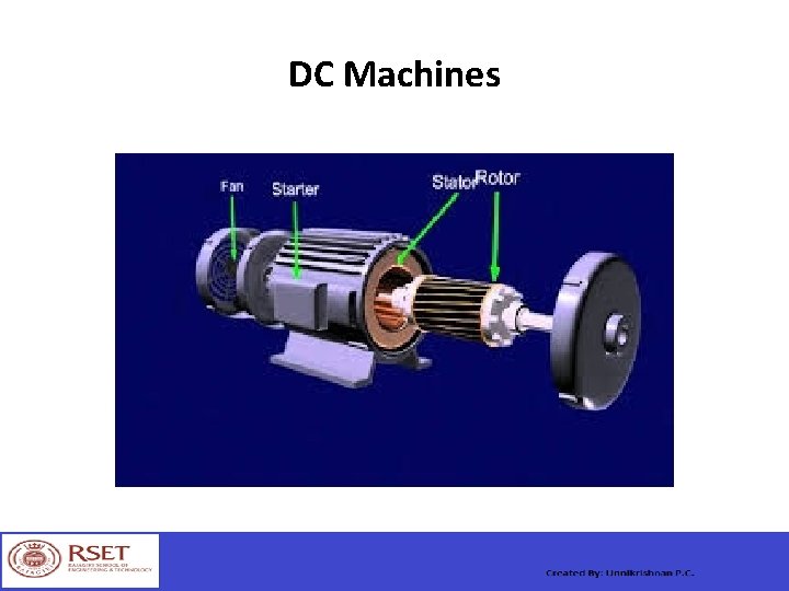
DC Machines
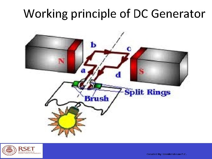
Working principle of DC Generator
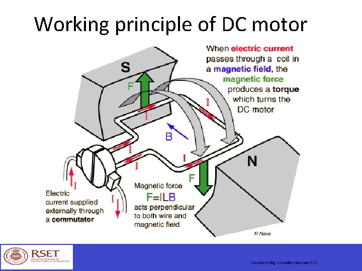
Working principle of DC motor
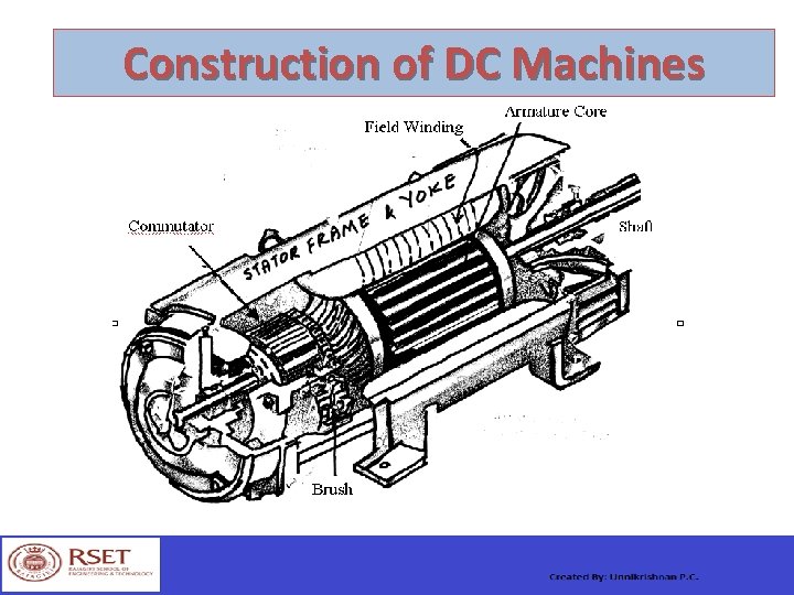
Construction of DC Machines
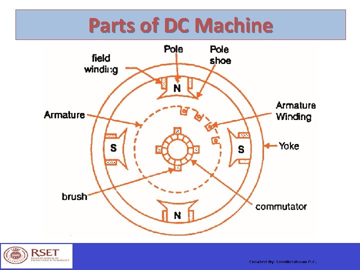
Parts of DC Machine
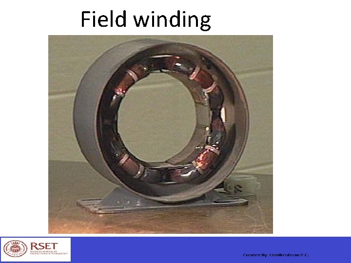
Field winding
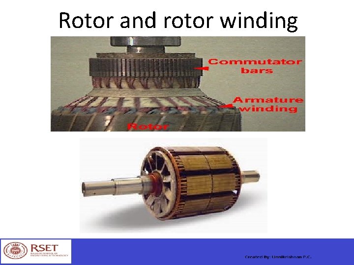
Rotor and rotor winding
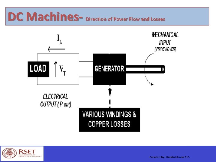
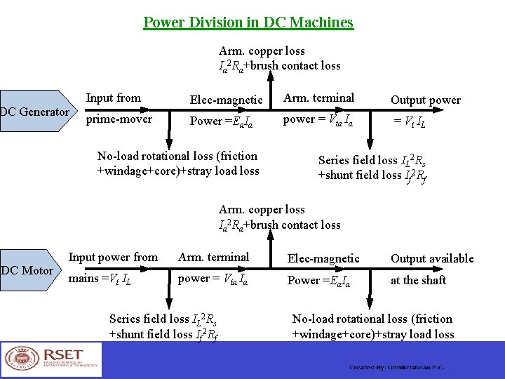
DC Machines- Direction of Power Flow and Losses
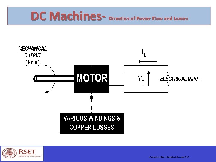
DC Machines- Direction of Power Flow and Losses
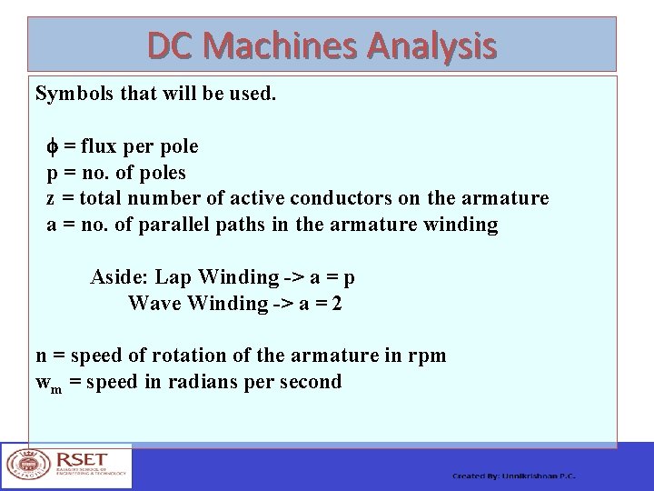
DC Machines Analysis Symbols that will be used. = flux per pole p = no. of poles z = total number of active conductors on the armature a = no. of parallel paths in the armature winding Aside: Lap Winding -> a = p Wave Winding -> a = 2 n = speed of rotation of the armature in rpm wm = speed in radians per second
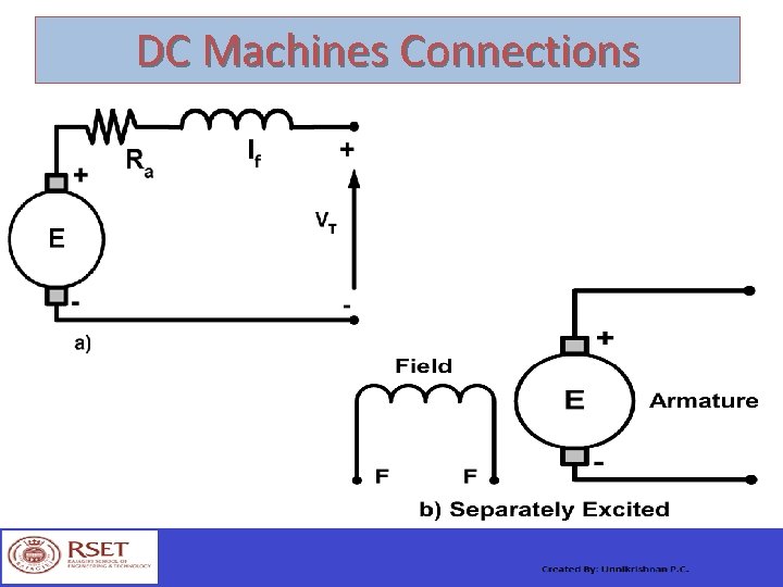
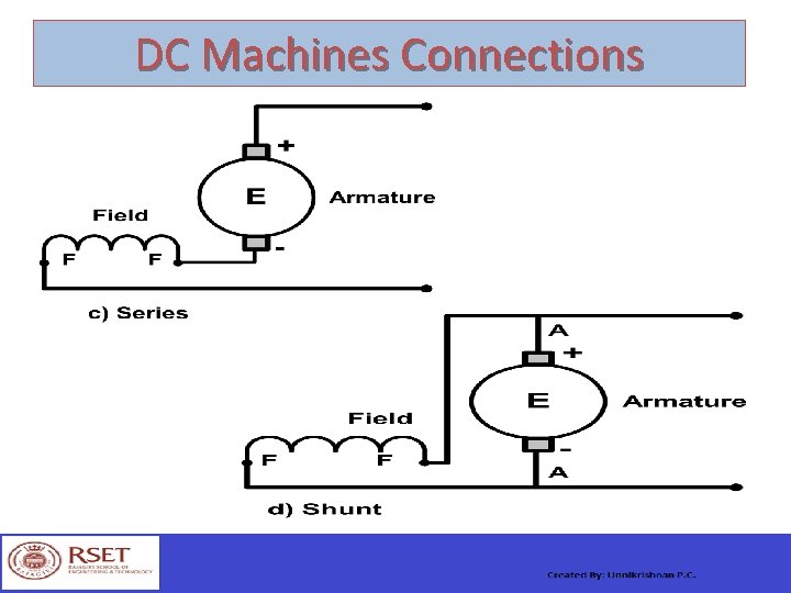
DC Machines Connections
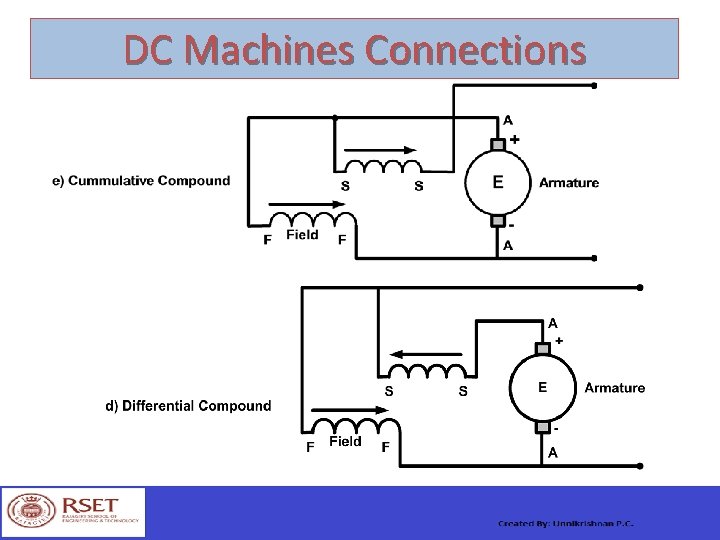
DC Machines Connections
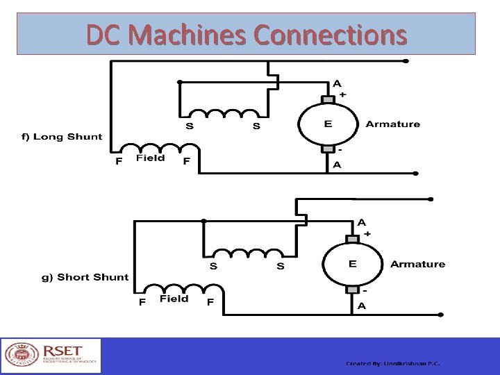
DC Machines Connections
DC Machines Connections
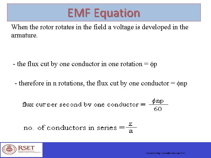
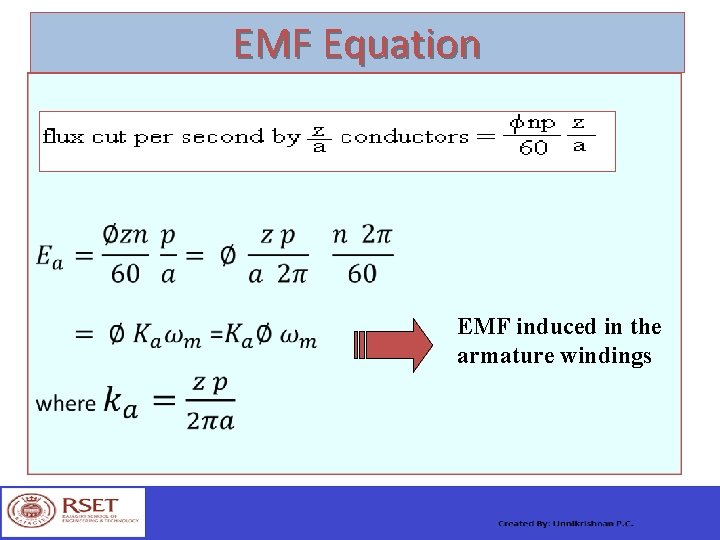
EMF Equation When the rotor rotates in the field a voltage is developed in the armature. - the flux cut by one conductor in one rotation = p - therefore in n rotations, the flux cut by one conductor = np
EMF Equation EMF induced in the armature windings
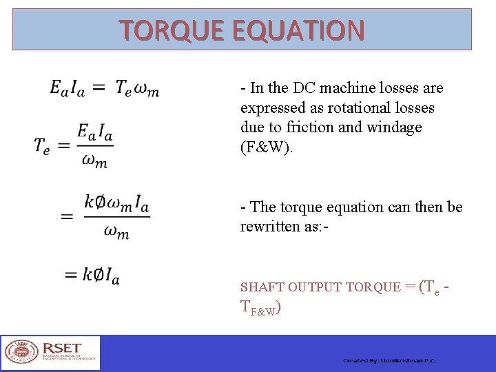
TORQUE EQUATION - In the DC machine losses are expressed as rotational losses due to friction and windage (F&W). - The torque equation can then be rewritten as: SHAFT OUTPUT TORQUE = (Te - TF&W)
DC Generator Note: VT = VL i. e. Terminal Voltage is the Load Voltage
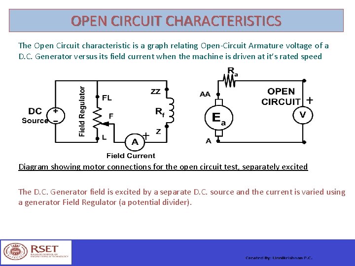
OPEN CIRCUIT CHARACTERISTICS The Open Circuit characteristic is a graph relating Open-Circuit Armature voltage of a D. C. Generator versus its field current when the machine is driven at it’s rated speed Diagram showing motor connections for the open circuit test, separately excited The D. C. Generator field is excited by a separate D. C. source and the current is varied using a generator Field Regulator (a potential divider).
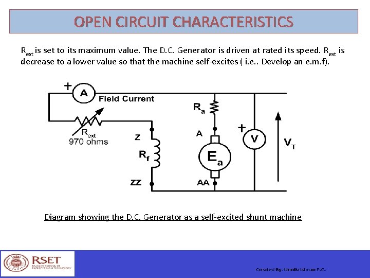
OPEN CIRCUIT CHARACTERISTICS Rext is set to its maximum value. The D. C. Generator is driven at rated its speed. Rext is decrease to a lower value so that the machine self-excites ( i. e. . Develop an e. m. f). Diagram showing the D. C. Generator as a self-excited shunt machine
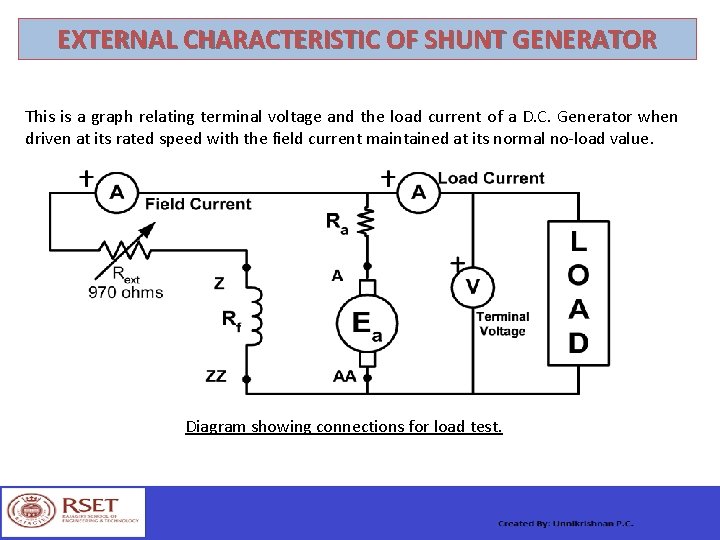
EXTERNAL CHARACTERISTIC OF SHUNT GENERATOR This is a graph relating terminal voltage and the load current of a D. C. Generator when driven at its rated speed with the field current maintained at its normal no-load value. Diagram showing connections for load test.
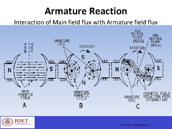
Armature Reaction Interaction of Main field flux with Armature field flux
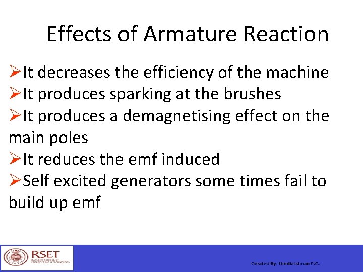
Effects of Armature Reaction It decreases the efficiency of the machine It produces sparking at the brushes It produces a demagnetising effect on the main poles It reduces the emf induced Self excited generators some times fail to build up emf
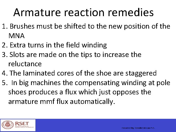
Armature reaction remedies 1. Brushes must be shifted to the new position of the MNA 2. Extra turns in the field winding 3. Slots are made on the tips to increase the reluctance 4. The laminated cores of the shoe are staggered 5. In big machines the compensating winding at pole shoes produces a flux which just opposes the armature mmf flux automatically.
Commutation The change in direction of current takes place when the conductors are along the brush axis During this reverse process brushes short circuit that coil and undergone commutation Due to this sparking is produced and the brushes will be damaged and also causes voltage dropping.
Losses in DC Generators 1. Copper losses or variable losses 2. Stray losses or constant losses Stray losses : consist of (a) iron losses or core losses and (b) windage and friction losses. Iron losses : occurs in the core of the machine due to change of magnetic flux in the core. Consist of hysteresis loss and eddy current loss. Hysteresis loss depends upon the frequency , Flux density , volume and type of the core.
Losses Hysteresis loss depends upon the frequency , Flux density , volume and type of the core. Eddy current losses : directly proportional to the flux density , frequency , thickness of the lamination. Windage and friction losses are constant due to the opposition of wind and friction.
Applications Shunt Generators: a. in electro plating b. for battery recharging c. as exciters for AC generators. Series Generators : a. As boosters b. As lighting arc lamps
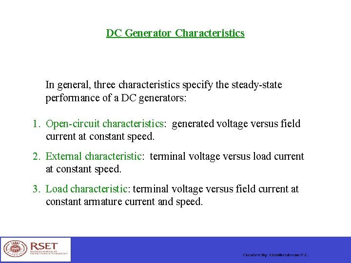
DC Generator Characteristics In general, three characteristics specify the steady-state performance of a DC generators: 1. Open-circuit characteristics: generated voltage versus field current at constant speed. 2. External characteristic: terminal voltage versus load current at constant speed. 3. Load characteristic: terminal voltage versus field current at constant armature current and speed.
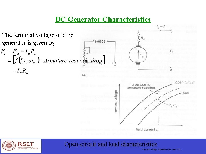
DC Generator Characteristics The terminal voltage of a dc generator is given by Open-circuit and load characteristics
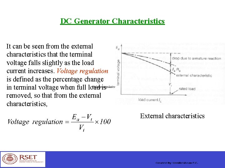
DC Generator Characteristics It can be seen from the external characteristics that the terminal voltage falls slightly as the load current increases. Voltage regulation is defined as the percentage change in terminal voltage when full load is removed, so that from the external characteristics, External characteristics
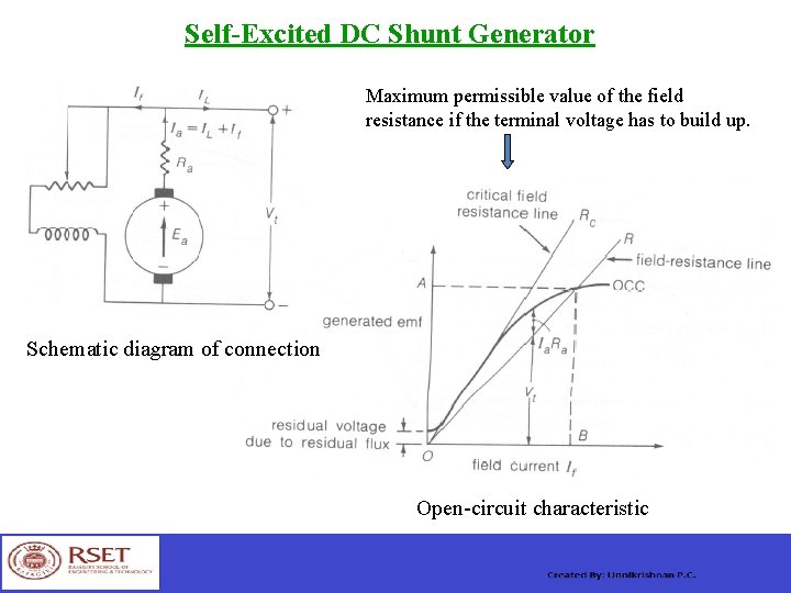
Self-Excited DC Shunt Generator Maximum permissible value of the field resistance if the terminal voltage has to build up. Schematic diagram of connection Open-circuit characteristic
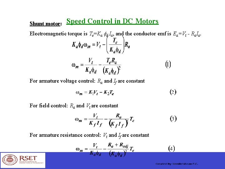
Shunt motor: Speed Control in DC Motors Electromagnetic torque is Te=Ka fd Ia, and the conductor emf is Ea=Vt - Ra. Ia. For armature voltage control: Ra and If are constant For field control: Ra and Vt are constant For armature resistance control: Vt and If are constant
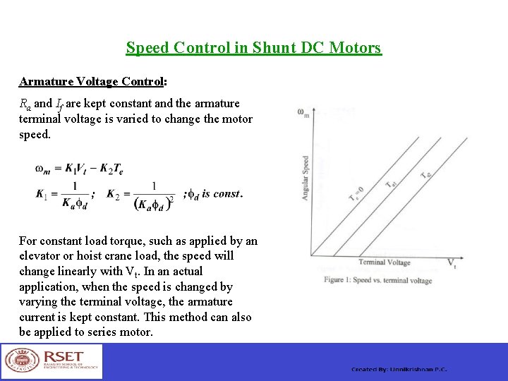
Speed Control in Shunt DC Motors Armature Voltage Control: Ra and If are kept constant and the armature terminal voltage is varied to change the motor speed. For constant load torque, such as applied by an elevator or hoist crane load, the speed will change linearly with Vt. In an actual application, when the speed is changed by varying the terminal voltage, the armature current is kept constant. This method can also be applied to series motor.
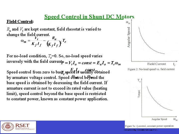
Field Control: Speed Control in Shunt DC Motors Ra and Vt are kept constant, field rheostat is varied to change the field current. For no-load condition, Te=0. So, no-load speed varies inversely with the field current. Speed control from zero to base speed is usually obtained by armature voltage control. Speed control beyond the base speed is obtained by decreasing the field current. If armature current is not to exceed its rated value (heating limit), speed control beyond the base speed is restricted to constant power, known as constant power application.
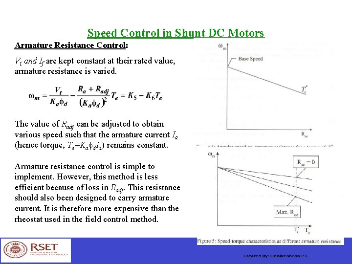
Speed Control in Shunt DC Motors Armature Resistance Control: Vt and If are kept constant at their rated value, armature resistance is varied. The value of Radj can be adjusted to obtain various speed such that the armature current Ia (hence torque, Te=Ka d. Ia) remains constant. Armature resistance control is simple to implement. However, this method is less efficient because of loss in Radj. This resistance should also been designed to carry armature current. It is therefore more expensive than the rheostat used in the field control method.
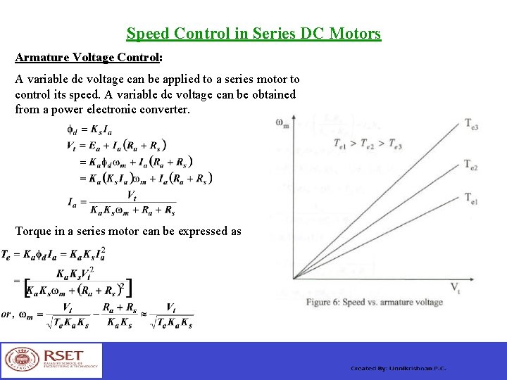
Speed Control in Series DC Motors Armature Voltage Control: A variable dc voltage can be applied to a series motor to control its speed. A variable dc voltage can be obtained from a power electronic converter. Torque in a series motor can be expressed as
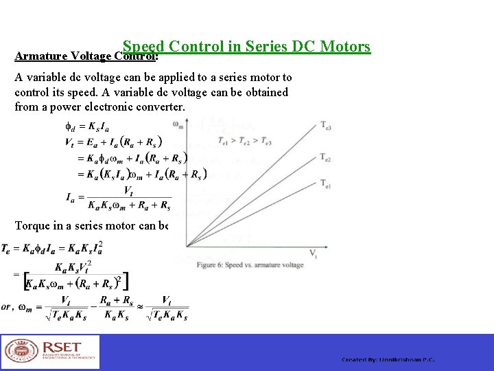
Speed Control in Series DC Motors Armature Voltage Control: A variable dc voltage can be applied to a series motor to control its speed. A variable dc voltage can be obtained from a power electronic converter. Torque in a series motor can be expressed as
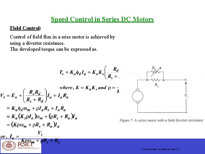
Speed Control in Series DC Motors Field Control: Control of field flux in a sries motor is achieved by using a diverter resistance. The developed torque can be expressed as.
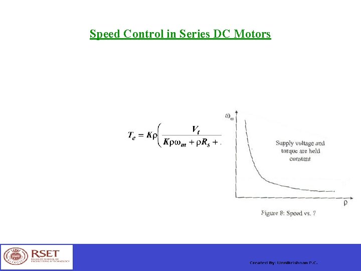
Speed Control in Series DC Motors
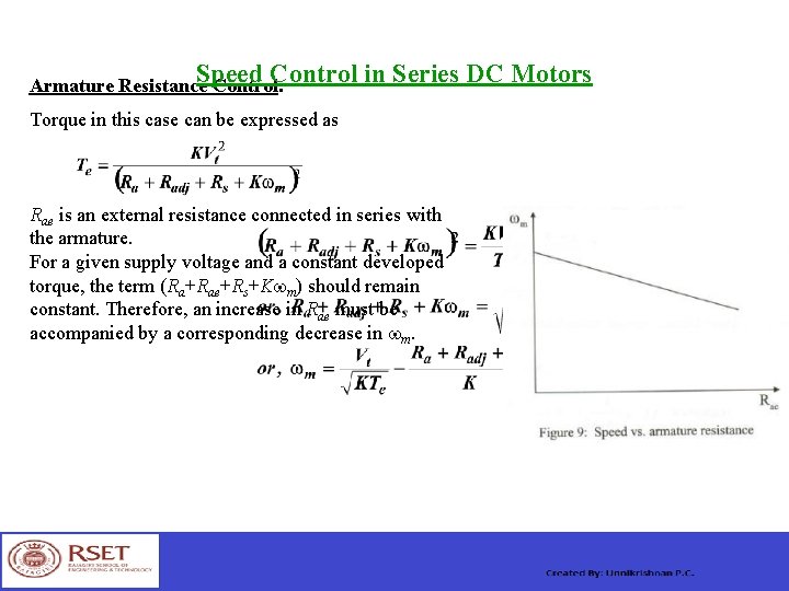
Speed Control in Series DC Motors Armature Resistance Control: Torque in this case can be expressed as Rae is an external resistance connected in series with the armature. For a given supply voltage and a constant developed torque, the term (Ra+Rae+Rs+Kwm) should remain constant. Therefore, an increase in Rae must be accompanied by a corresponding decrease in wm.
Power Division in DC Machines Arm. copper loss Ia 2 Ra+brush contact loss DC Generator Input from Elec-magnetic Arm. terminal Output power prime-mover Power =Ea. Ia power = Vta Ia = Vt IL No-load rotational loss (friction +windage+core)+stray load loss Series field loss IL 2 Rs +shunt field loss If 2 Rf Arm. copper loss Ia 2 Ra+brush contact loss DC Motor Input power from Arm. terminal Elec-magnetic Output available mains =Vt IL power = Vta Ia Power =Ea. Ia at the shaft Series field loss IL 2 Rs +shunt field loss If 2 Rf No-load rotational loss (friction +windage+core)+stray load loss
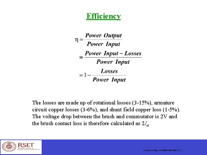
Efficiency The losses are made up of rotational losses (3 -15%), armature circuit copper losses (3 -6%), and shunt field copper loss (1 -5%). The voltage drop between the brush and commutator is 2 V and the brush contact loss is therefore calculated as 2 Ia.
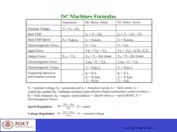
DC Machines Formulas
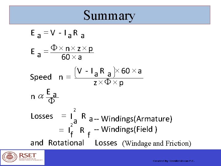
Summary E a = V - I a R a F ´ ´ ´ n z p = Ea 60 ´ a V - I a R a ö÷÷ø ´ 60 ´ a Speed n = z´F ´p Ea a n F æ ç ç è 2 Losses = I R a -- Windings(Armature) a 2 = I R -- Windings(Field ) f f and Rotational Losses (Windage and Friction)