EE 216 Electrical Engineering Dr Unnikrishnan P C


- Slides: 29
EE 216 Electrical Engineering Dr. Unnikrishnan P. C. Professor, EEE
Synchronous Generator-Alternator
Stator Construction • Stator is identical to the induction motor • Laminated low silicon steel rings joined together • Slots insulated with Mylar • Example of 36 slot stator with 3 coil conductors per slot, 12 slots per phase
Stator Construction
Rotor Construction Two Types of Rotor • Salient Pole • Cylindrical
Rotor Construction
Salient-Pole Rotor with brushless excitation
Rotor Construction
Operation as a Synchronous Generator
Equations
• Synchronous Impedance
Phasor Diagram of an Alternator at Lagging pf load
Voltage Regulation A convenient way to compare the voltage behaviour of two generators is by their voltage regulation (VR). •
EMF Method or Synchronous Impedance Method Circuit diagram for open circuit and short circuit test on alternator
EMF Method …… • Equivalent circuit on short circuit
OCC & SCC of an Alternator
EMF Method …… No load induced e. m. f. per phase, Eph can be determined from the equation
EMF Method Advantages & Limitations • Advantage: synchronous impedance Zs for any load condition can be calculated. Hence regulation of the alternator at any load condition and load power factor can be determined. • Limitation: This method gives large values of synchronous reactance. This leads to high values of % regulation than the actual. Hence this method is called Pessimistic method.
MMF Method or Ampere Turn Method • The effect of armature leakage reactance by an equivalent additional m. m. f so that this m. m. f may be combined with the armature reaction m. m. f. • An alternator requires m. m. f. which is product of field current and turns of field winding-two components 1. An m. m. f. necessary to induce the rated terminal voltage on open circuit. 2. An m. m. f. equal and opposite to that of armature reaction m. m. f. • The number of turns in the field winding is not known normally, so the m. m. f. is calculated in terms of the field current itself.
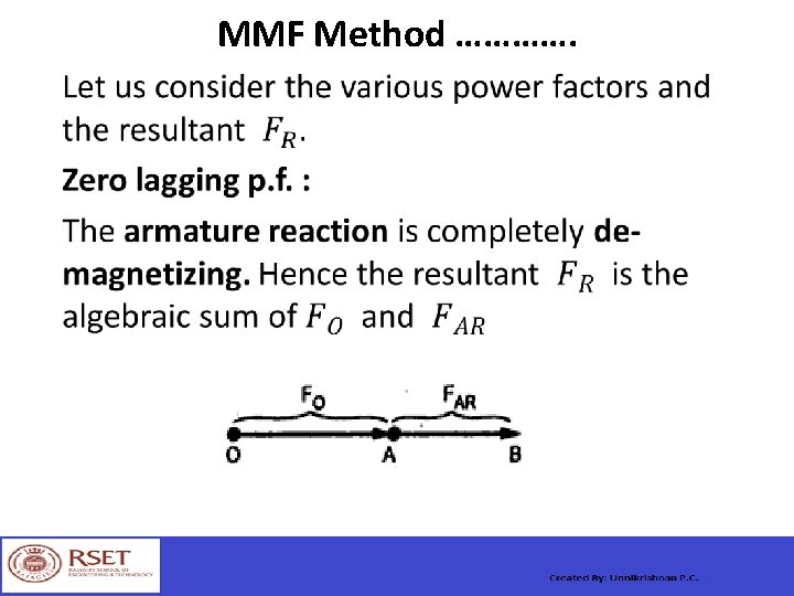
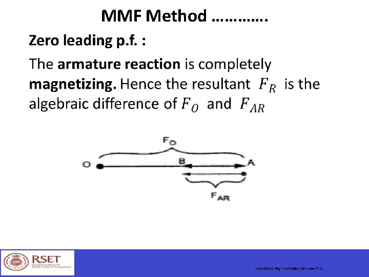
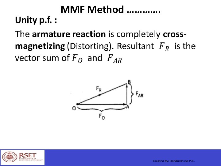
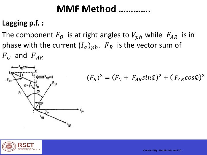
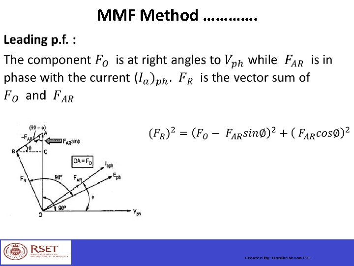
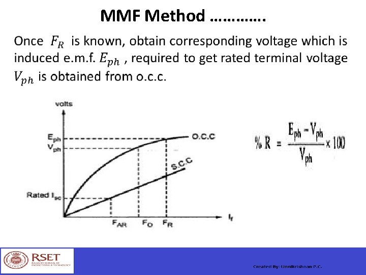
MMF Method ………….
Operation as a Synchronous Motor