EDME 111 L2 Dr Poonam Kumari LETTERING Writing

 using letters which")


 Specifications Type Value Size (mm)")


 defines dimension as a numerical value expressed in appropriate")


- Slides: 25
ED-ME 111 L-2 Dr. Poonam Kumari
LETTERING Writing text on a drawing (e. g. titles, dimensions, scales) using letters which can be alphabets, numerals, symbols or punctuation marks to convey detailed information. Features of Lettering 1. Legibility, uniformity, ease, rapidity of execution and reproducibility 2. No ornamental or artistic and cursive style of letter 3. Letters should be distinguishable from each other in order to avoid any confusion even in case of slight mutilations Standard followed IS 9609 (Part 0): 2001 & SP 46: 2003 (lettering for technical drawings). This BIS standard is based on ISO 3098 -0: 1997
Types of Lettering • Single stroke - Thickness of the line of the letter should be such as is obtained in one stroke of the pencil. Does not mean that the letter should be made in one stroke without lifting the pencil. • Double stroke- When more thickness is given to single stroke letters, it is known as double stroke or gothic letters. • BIS (SP 46: 2003) - Gives dimensions for lettering & types • Type A - Height of capital letter is divided into 14 parts • Type B – Height of capital letter is divided into 10 parts Both types can be Vertical or Inclined at 75˚ to the horizontal Line Width of Type A ˂ Type B Basic Strokes
Examples Height and width of letters “I” letter “A” letter “B”ofletter BIS (SP 46: 2003) has recommended the heights letters as: 1. 8, 2. 5, 3. 5, 5, 7, 10, 14 & 20 mm 4 5 Sl. no 1 2 3 4 5 6 1 1 2 1 Items on a drawing Name of the company 3 Drawing numbers, letters 3 denoting section planes 2 Title of the drawing Sub- titles & Headings Dimensioning, notes, schedules & material lists. Alteration entries and tolerances Size (mm) 6 20 10, 14, 10, 14 7, 10 5, 7 3. 5 Total height of lowercase letters equals that of capital letters. The height-to-width ratio for letters varies between 7 : 5 or 7 : 6
A & B type Lettering BIS (SP 46: 2003) Specifications Type Value Size (mm) Capital letter height A h 2. 5 3. 5 5 7 10 14 20 B h 2. 5 3. 5 5 7 10 14 20 A a=(5/7)h - 2. 5 3. 5 5 7 10 14 B a=(7/10)h - 2. 5 3. 5 5 7 10 14 A b=(1/14)h . 18 . 25 . 35 . 7 1 1. 4 B b=(1/10)h . 25 . 35 . 7 1 1. 4 2 A c=(1/7)h . 35 . 7 1 1. 4 2 2. 8 B c=(1/5)h . 5 . 7 1 1. 4 2 2. 8 4 Minimum spacing between words A d=(3/7)h 1. 05 1. 5 2. 1 3 4. 2 6 8. 4 B d=(3/5)h 1. 5 2. 1 3 4. 2 6 8. 4 12 Minimum spacing between baselines A e=(10/7)h 3. 5 5 7 10 14 20 28 B e=(7/5)h 3. 5 5 7 10 14 20 28 Lowercase letter height Thickness of lines Spacing between characters
Vertical Capital Letters and Numerical Vertical Lowercase Letters
Fraction & Indices lettering 1. Height of numerator and denominator = 3/4 th of height of nonfractioned number 2. Spacing between division bar and numerator or denominator should Inclined Capital Letters At 75˚ be such that the total height of fraction will The height of index is be twice of that of non half of height of a -fractioned number base letter
Few Tips If you put the central horizontal strokes of the letters B, E, F, and H at midheight, they will appear to be below center. To overcome this optical illusion, draw the strokes B, E, F, and H slightly above the center as you letter, keeping letters uniform, as in the second example of fig(right below). Use extremely light horizontal guidelines to keep letter height uniform as shown in Figure (left above). Do not use vertical guidelines to space the distance from one letter to the next within a word or sentence. This should he done by eye while lettering. Some combinations, such as LT and VA, may have to be slightly closer than other letters to look correctly spaced. In some cases the width of a letter may be decreased slightly. In typesetting, pairs of letters that need to be spaced more closely to appear correctly are called kerned pairs.
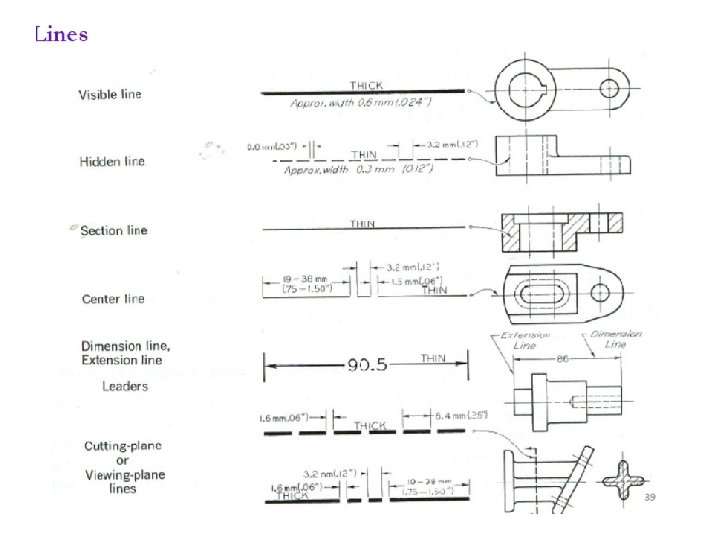
DIMENSIONING BIS (SP 46: 2003) defines dimension as a numerical value expressed in appropriate units of measurement and indicated graphically on technical drawings with lines, symbols & notes. Features of Dimensioning 1. Units of measurement – length (mm), angles (degrees ˚) 2. Symbols – incorporated to indicate specific geometries 3. Notes – to give specification to particular feature or specific information necessary during manufacturing of the job Elements of Dimensioning • Object lines • Extension lines • Dimension lines • Leader lines • Arrowheads • Dimensions
Examples for elements of dimensioning Elements of dimensioning Definition Object line A line on the drawing whose length is to be shown is called an object line. In case of angles 2 lines forming angle will be object lines. Extension line An extension line is a thin continuous line drawn perpendicular to an object line. It extends by about 3 mm beyond the dimension line Dimension line is drawn between 2 extension lines parallel to the object line. One dimension line represents one dimension. For angles a curved dimension line as arc with center at the vertex of angle is drawn. It is terminated by arrowheads touching the extension lines Center line A center-line is a thin, dark line alternating long and short dashes. Center-lines are commonly used as extension lines in locating holes and other symmetrical features. When extended for dimensioning. Centerlines cross over other lines of the drawing without gaps. Always end center-lines using a long dash.
Elements of dimensioning Definition Leader line A leader or a pointer is a thin continuous line connecting a note or a dimension figure with the feature to which it applies. Never drawn vertical of horizontal but at some angle. A dot is used instead of an arrowhead if the leader ends inside the object. Arrowheads An arrowhead is placed at each end of a dimension line. Its pointed end touches an extension line. The size of an arrowhead should be proportional to the length of the dimension line. The length of the arrowhead should be about three times its maximum width. Dimension Placed near the middle and above the dimension lines or at the center of dimension lines by breaking them. As all dimensions of a drawing are in the same unit, instead of unit a note (ALL DIMENSIONS IN MM) preferable at the left hand side of title block is written. Dimension text should be uniform for all features.
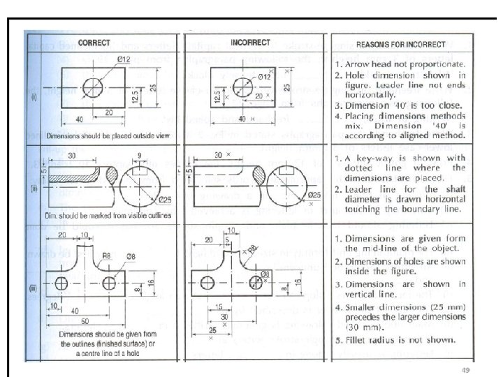
Best practices for dimension & extension lines 1. 2. 3. 4. The shorter dimensions are nearest to the object outline. Dimension lines should not cross extension lines as in Figure (b), which results from placing the shorter dimensions outside. Note that it is perfectly satisfactory to cross extension lines (Figure a), but they should not be shortened (Figure c). Dimension lines should not cross each other & any other lines of the object. However extension lines can cross both (fig 1). A dimension line should never coincide with or extend from any line Fig 1 of the drawing (Figure d).
Best practices for dimension & extension lines 5. Dimensions should be lined up and grouped together as much as possible, as in Figure 2 a, and not as in Figure 2 b. 6. In some cases, extension lines and center-lines must cross visible lines of the object (Figure 3 a). When this occurs, gaps should not be left in the lines (Figure 3 b). Fig 2 7. Dimensions should be placed outside the views (a). Placed inside if more clear and readable (b). Fig 3
Best practices for arrowheads & centerlines 1. Arrowheads should ordinarily be drawn within the limits of the dimensioned feature. But when the space is too narrow, they may be placed outside (fig 4) Fig 4 Fig 5 a 1. Center line(axis) itself shall not be used as a dimension line with arrowheads as its ends. Fig 5 a 2. Center line(axis) itself shall not be used as a dimension line with arrowheads as Fig 5 b its ends. Fig 5 b 3. Center-lines should not extend from view to view.
Best practices for dimensions 1. 2. All dimensions must be given. There should not be need for calculation, assumption or direct measurement for any dimension. Dimension should be on feature’s best view. Each dimension should be given only once. No dimension should be redundant / superfluous (repeated) (fig 6). Not even on another view (fig 7) or by different ways. Fig 6 3. 4. Dimensions Figshall be given to 1 visible lines and not to hidden lines Each feature is dimensioned and positioned where its shape shows. Fig 7 Fig 2
Best practices for dimensioning pictorial view 1. Principal lines are dimensioned in pictorial view. Dimension and extension lines are drawn in directions that are parallel to the principal lines. For non-principal lines, its coordinates, in the direction parallel to the principal lines are given. (fig L) Fig. L 1 Fig R 2. In case of oblique parallel projections, along with principal lines, those lines which are projected with true length are also dimensioned. In those cases, extension lines are drawn perpendicular to dimension lines. (fig R)
Systems of dimensioning For placing the dimensions on the drawing, following systems can be adopted. Aligned system Unidirectional system 1. Dimensions are placed perpendicular to the dimension line. 2. Horizontal and inclined dimensions can be read from the bottom of the drawing. Vertical dimensions can be read from the right-hand side of the drawing. 3. All dimensions are placed above the midpoint of dimension lines. 1. Dimensions are placed vertically irrespective of dimension lines. 2. All dimensions can be read from the bottom of the drawing. 3. Horizontal dimensions are placed above the midpoint of dimension lines. Vertical and inclined dimensions are placed at the middle of dimension lines by breaking them. Note All the dimensions on a drawing must be shown using either Aligned System or Unidirectional System. Two systems should not be mixed on the same drawing.
Arrangement of dimensions Chain dimensioning Parallel dimensioning Combined dimensioning All dimensions are aligned in such a way that an arrowhead of one dimension touches tipto-tip the arrowhead of adjacent dimension. The overall dimension is placed outside the other smaller dimensions. All dimensions are shown from a common reference line. All dimensions share a common extension line. This is adopted when dimensions have to be established from a particular datum surface. Both the methods (chain & parallel) are used on the same drawing Used when the possible accumulation of tolerances does not endanger the fundamental requirement of the component. Used where a number of dimensions have a common datum feature
Dimensioning of circular features 1. By diameter instead of radius, precede by Ø symbol, leaders. 2. For more than 1 hole of same Ø, the dim. of a hole with a note will give idea about the dimensions of all the holes. (fig 8 a, b) Hole dimensioning If there are different categories (each with same Ø holes) of holes, use reference letters and noted below the view. (fig 8 b) Standard symbols for dimensions Fig 9 Fig 8 Equispaced holes (fig 9) where 5 x 18 means 6 holes center-to-center distance 18 mm
Dimensioning of arc, fillets, angles & cyl. Arc shown by radius, precede by R symbol, center marked by cross, leaders. For large or small arc, center mark is omitted (10) Cyl. dimensioning Fig 10 Angle dimensioning Fillets are of standard size, such as metric R 3 and R 6. Thus, a note in the or simply lower portion of the drawing is given. FILLETS R 6 AND ROUNDS R 3 UNLESS OTHERWISE SPECIFIED or ALL CASTING RADII R 6 UNLESS NOTED or ALL FILLETS AND ROUNDS R 6.
Dimensioning of spherical, conical, tapered Spherical feature dimensioning Conical feature dimensioning Flat tapered feature dimensioning
Dimensioning- square, chamfered, countersunk Square feature dimensioning External Chamfer dimensioning Internal Chamfer dimensioning Countersunk dimensioning
Dimensioning- screw threads Metric thread Nominal dia. = 12 mm Depth of drilled hole = 22 mm Threaded length = 18 mm External thread Internal thread Symbols & abbreviations used in dimensioning